Subscribe to Our Youtube Channel
Summary of Contents for Velleman K8059
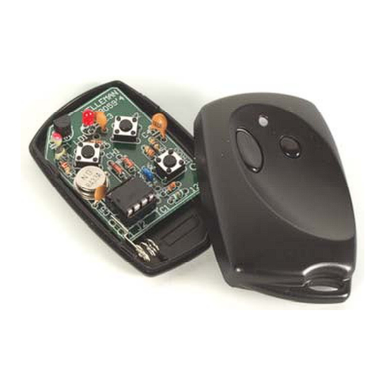
- Page 1 Total solder points: 63 Difficulty level: beginner 1 advanced 2 CHANNEL RF CODELOCK TRANSMITTER K8059 ILLUSTRATED ASSEMBLY MANUAL H8059IP-1...
- Page 3 Open field range of up to 30m possible Dimensions: 63 x 40 x 16mm (2.5" x 1.6" x 0.6") Velleman hereby certifies that the device K8059 meets the essential requirements and all other relevant stipulations of directive 1999/5/EG and 1995/5/EC.
- Page 4 Assembly hints 1. Assembly (Skipping this can lead to troubles ! ) Ok, so we have your attention. These hints will help you to make this project successful. Read them carefully. 1.1 Make sure you have the right tools: • A good quality soldering iron (25-40W) with a small tip.
- Page 5 3- Trim excess leads as close as possible to the solder joint REMOVE THEM FROM THE TAPE ONE AT A TIME ! AXIAL COMPONENTS ARE TAPED IN THE CORRECT MOUNTING SEQUENCE ! You will find the colour code for the resistances and the LEDs on our website: http://www.velleman.be/common/service.aspx...
- Page 6 Construction 1. Diodes. Watch the polarity! Resistors 5. Push buttons 1/8W R... D... CATHODE R1 : 33K (3 - 3 - 3 - B) R2 : 33K (3 - 3 - 3 - B) D1 : BAT85 SW1 : KRS0611 R3 : 33K (3 - 3 - 3 - B) D2 : BAT85 SW2 : KRS0611...
- Page 7 Check for good attachment of 12. Sticker the solder to the contacts 10. Transistor Affix the supplied sticker to the back of the housing. 8. LED Velleman COLOR= 2...5 T1 : MPSH10 LD1 : 3mm blue 433,92 MHz SRFCE CATHODE...
- Page 8 13. Use The transmitter comes with a factory set default code. However, for security reasons, it might be wise not to use the default code. 1. To program your unique code : Hold SW1(*) (left button). Briefly press the 'program'-button (SW3) 3 times. The LED will flash 3 times. Release SW1.
- Page 9 3. Compatibility with previous transmitters (K6706 - K6706A - K6706B - K6706G) : 3 different codes can be generated, solder a bridge as indicated below. MODIFY EXCISTING TRANSMITTERS AND RECEIVERS : UM3758 UM3758 UM3758 No code Pin1with Pin1with...
-
Page 10: Schematic Diagram
Schematic diagram 14. Schematic diagram. 47-1/8W 2K7-1/8W 33K-1/8W LED3RL GP0/CIN+/ICSPDAT GP1/CIN-/ICSPCLK GP2/T0CKl/INT/COUT MPSH10 GP3/MCLR/Vpp 100n 5V1/0.5W GP4/T1G/OSC2/CLKOUT 100p 33K-1/8W 33K-1/8W GP5/T1CKI/OSC1/CLKIN PIC12F629 100p SAW433 BAT1 220-1/8W SW KRS0611 BAT85 BAT85 100p SW KRS0611 SW KRS0611... - Page 11 15. PCB...
- Page 12 VELLEMAN Components NV Legen Heirweg 33 9890 Gavere Belgium Europe www.velleman.be www.velleman-kit.com Modifications and typographical errors reserved © Velleman Components nv. H8059IP - 2004 - ED1 (rev. 1.0) 5 4 1 0 3 2 9 3 1 2 0 7 7...


Need help?
Do you have a question about the K8059 and is the answer not in the manual?
Questions and answers