
Related Manuals for PeerlessBoilers LC Series


Summary of Contents for PeerlessBoilers LC Series
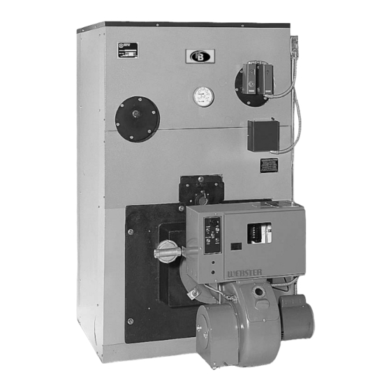
- Page 1 Series LC/LCE Oil, Gas & Gas/Oil Boilers – Steam I n s t a l l a t i o n , O p e r a t i o n & M a i n t e n a n c e M a n u a l...
-
Page 2: Table Of Contents
TABLE OF CONTENTS TABLE OF CONTENTS USING THIS MANUAL 5. VENTING A. INSTRUCTION MANUALS ....1 6. INSTALL THE BURNER B. SPECIAL ATTENTION BOXES ... .1 A. -
Page 3: Using This Manual
USING THIS MANUAL USING THIS MANUAL A. INSTRUCTION MANUALS DANGER The Series LC/LCE Installation, Operation & Indicates a condition or hazard which will cause Maintenance Manual is divided into four basic sections: severe personal injury, death or major property 1. Preinstallation (Section 1) damage. -
Page 4: Preinstallation
PREINSTALLATION 1. PREINSTALLATION NOTICE The equipment must be installed in accordance with installation requirements of the authority having jurisdiction or, in the absence of such requirements, to the current edition of the National Fuel Gas Code , ANSI Z223.1/NFPA 54. Where required by the authority having jurisdiction, the installation must conform to American Society of Mechanical Engineers Safety Code for Controls and Safety Devices for Automatically Fired Boilers, ASME CSD-1. -
Page 5: Clearance From Combustible Construction
PREINSTALLATION B. CLEARANCE FROM COMBUSTIBLE D. CHIMNEY OR VENT CONSTRUCTION 1. Inspect the existing chimney or vent system. Make sure it is in good condition. Inspect chimney liner Provide the following minimum clearances to and repair or replace if necessary. combustible construction. -
Page 6: Boiler Setting
PREINSTALLATION Figure 1.4: Foundation Layout 8. Exterior Vents: E. BOILER SETTING a) Insulate sufficiently to ensure adequate draft and 1. If the boiler room floor is not level or if additional to prevent vent damage due to condensation. structural support is needed, provide a good, level 9. -
Page 7: Installation Survey
You can also use this survey to locate system problems which will have to be corrected. To obtain copies of the Steam Installation Survey, contact your PB Heat representative or download it from PeerlessBoilers.com. G. PLANNING THE LAYOUT Prepare sketches and notes of the layout to minimize the possibility of interferences with new or existing equipment, piping, venting and wiring. - Page 8 PREINSTALLATION...
- Page 9 PREINSTALLATION...
- Page 10 PREINSTALLATION Table 1.3: Standard and Optional Sections for Knockdown Boilers 15 psig Steam MAWP Sections Standard w/Inspection Tappings Part # Stock Code Part # ITP Stock Code Front LC-1001 86000 LC-1013 86010 Intermediate LC-1000 86004 LC-1014 86014 LWCO Intermediate LC-1000-1 86005 LC-1014-2 86092...
- Page 11 PREINSTALLATION Table 1.5B: Burner Mounting Plates Boiler Model Model LCE-13 LCE-14 LCE-15 LCE-16 LCE-17 LCE-18 LCE-19 LCE-20 LCE-21 LCE-22 LCE-23 LCE-24 86074* CF2300AKG CF2300AKB 86083* 86083* Beckett CF2500 86074* 86074* Available CF3500AKM 86083* 86083* 86083* CF3500AKL 86080* 86080* 801CRD 86073 86073 Carlin 1050FFD...
-
Page 12: Place The Boiler
PLACE THE BOILER 2. PLACE THE BOILER 2. Remove lifting frame and hardware. A. PACKAGED BOILER 3. Proceed to Section D: Install Coils or Plates 1. Remove crate top and sides. Remove any loose cartons. Remove burner support pedestal and nipple, if supplied C. -
Page 13: The Sections
PLACE THE BOILER WARNING The sections are heavy and must be supported securely. 10. Lift up the Rear Section and move into position on the steel channels on the boiler foundation. 11. Screw a 3" pipe at least 30 inches long into the lower 3"... - Page 14 PLACE THE BOILER Figure 2.4: Install Additional Sections. Use level on each section as tie rod bolts are drawn up.
- Page 15 PLACE THE BOILER Figure 2.5: Series LC Boiler Assembly – Right Side View...
- Page 16 PLACE THE BOILER Figure 2.6: Series LCE Boiler Assembly – Right Side View...
- Page 17 PLACE THE BOILER 16. To properly assemble LC/LCE sections in the field, 17. Repeat with the remaining sections. the following steps must be followed to ensure that a. Save the LWCO Intermediate with two 1" no damage occurs to the tie rod lugs. A 0-100 ft-lbs tappings (for level control) for use as the section torque wrench is required.
- Page 18 PLACE THE BOILER Figure 2.9: LC/LCE Boiler Section Assembly Sequence...
-
Page 19: Install Coils Or Plates
PLACE THE BOILER D. INSTALL COILS OR PLATES E. HYDROSTATIC TEST THE BOILER 1. Remove the coil cover plates, gaskets and mounting 1. Install a drain valve in the Rear Section, Tapping 13. hardware, located in the Flue Box Carton. See Figure 8.2. - Page 20 PLACE THE BOILER Table 2.2: Tankless Coil Ratings Heater No. Heater No. Heater No. Two Heaters No. Two Heaters No. Two Heaters No. X-1020 X-1021 X-1022 X-1020 X-1021 X-1022 Model Location Location Location Location Location Location LC-04 – – – –...
-
Page 21: Apply Cleanout Cover Plates
PLACE THE BOILER APPLY CLEANOUT COVER PLATES 1. Apply the Cleanout Cover Plates on the tops of the section joints as shown in Figure 2.11. 2. Pre-assemble a steel flat washer and steel nut on the carriage bolts. Place a carriage bolt into each side of the cleanout opening as shown in the figure. -
Page 22: Install Flue Baffles
PLACE THE BOILER H. INSTALL FLUE BAFFLES INSTALL CHAMBER LINER 1. Remove the Front Cleanout Plate from Front 1. (LCE) Remove Ceramic Fiber Liner from Jacket Section. Carton E. Place the liner on the floor of the combustion chamber. Place the front end of the liner 2. -
Page 23: Pipe The Boiler
PIPE THE BOILER 3. PIPE THE BOILER 5. Counterflow Gravity systems require the boiler steam A. PREPARATION line to enter the top of the steam main. See Figure 3.2 for this special case. 1. The boiler must be pressure tested as outlined in the chapter “Place the Boiler Sections”... -
Page 24: Multiple Boiler Installations
PIPE THE BOILER 3. On pumped return systems, install a boiler cock after the pump to allow throttling of the pump discharge. The pressure after the boiler cock should be no more than 5 psig above the boiler operating pressure. Pumping the water into the boiler too fast will cause collapse of the water level and level control problems. - Page 25 PIPE THE BOILER Figure 3.3: Supply and Return Piping – Pumped Return and Parallel Flow Gravity Systems...
- Page 26 PIPE THE BOILER Figure 3.4: Piping Multiple Boilers, Typical, Gravity Return Systems Figure 3.5: Piping Multiple Boilers, Typical, Pumped Return Systems...
-
Page 27: Assemble The Jacket
ASSEMBLE THE JACKET 4. ASSEMBLE THE JACKET 2. Attach the Middle Front Panel and Lower Front Rail A. PREPARE THE PARTS in the same manner. 1. Collect all the jacket cartons: Jacket Front & Back 3. Position the Jacket Assembly with the front panels Carton plus Jacket Side &... - Page 28 ASSEMBLE THE JACKET Figure 4.2: Jacket Assembly...
-
Page 29: Venting
VENTING/INSTALL THE BURNER 5. VENTING Refer to Chapter 1, Preinstallation, Section D. Chimney or Vent for installation requirements. Refer to Chapter 9, Starting the Boiler, Section C. Run Burner Check Out for damper settings and draft requirements. 6. INSTALL THE BURNER 3. - Page 30 INSTALL THE BURNER Figure 6.1: Combustion Chamber Layout – See Table 6.1 for Dimensions Table 6.1: Combustion Chamber Dimensions Chamber Burner Front Plate Extension Past Jacket (Inches) Length Model “A” Gordon- Power Beckett Carlin Webster (Inches) Piatt Flame LC-04 18⁷⁄₈ 6¹⁄₈...
-
Page 31: Connect Fuel Piping
CONNECT FUEL PIPING 7. CONNECT FUEL PIPING A. GENERAL 1. Read the Burner Instruction Manual, supplied with the boiler or with the burner if purchased separately. Review applicable code requirements for burner and fuel piping installations. 2. Install piping to allow removal of burner and access to combustion chamber for cleaning or service. - Page 32 CONNECT FUEL PIPING Table 7.1: Capacity of Gas Supply Pipe in Cubic Feet Per Hour of Natural Gas for Pressure Drop of 0.3 inch Water Column. Pipe Length 1-1/4" 1-1/2" 2" 2-1/2" 3" 4" 6" (Feet) Pipe Pipe Pipe Pipe Pipe Pipe Pipe...
-
Page 33: Install Safety Valves
INSTALL CONTROLS, TRIM & WIRING 8. INSTALL CONTROLS, TRIM & WIRING A. INSTALL SAFETY VALVES D. INSTALL PRESSURE CONTROLS 1. Pipe the Pop Safety Valve on a tee mounted in the 1. Pipe the Steam Pressure Gauge and Boiler Limit and 2¹⁄₂"... -
Page 34: Install Control Wiring
INSTALL CONTROLS, TRIM & WIRING 3. Install line voltage wiring in conduit. G. INSTALL CONTROL WIRING 4. Do not install single pole switches, including safety 1. Wire the boiler according to the wiring diagrams controls, in a grounded line. supplied with the burner and the boiler (in the Boiler Envelope). - Page 35 INSTALL CONTROLS, TRIM & WIRING Figure 8.2: Control and Pipe Tapping Locations...
- Page 36 INSTALL CONTROLS, TRIM & WIRING Figure 8.3: Control and Pipe Tapping Locations...
- Page 37 INSTALL CONTROLS, TRIM & WIRING Figure 8.4: Optional Model 67PE2 Float Low Water Cutoff Figure 8.5: Optional Model 47-2 Low Water Cutoff/Feeder – Use only up to Model LC-07...
- Page 38 INSTALL CONTROLS, TRIM & WIRING Figure 8.6: Optional Float Type Pump Control/Low Water Cutoff, Model 157...
- Page 39 INSTALL CONTROLS, TRIM & WIRING Figure 8.7: Optional Feeder/Low Water Cutoff, Type 51-2...
- Page 40 INSTALL CONTROLS, TRIM & WIRING Figure 8.8: Suggested Piping – Single Tankless Coil Installation Figure 8.9: Suggested Piping – Dual Tankless Coil Installation...
-
Page 41: Starting The Boiler
STARTING THE BOILER 9. STARTING THE BOILER When a barometric draft regulator is installed in the A. CHECK THE PIPING venting system, adjust the boiler damper for 0" wc 1. Steam Piping pressure reading at the damper. Adjust the draft regulator for -0.05"... - Page 42 STARTING THE BOILER 2. The boiler must be cleaned to remove any 9. Open the make-up water valve to continuously feed accumulation of oil, grease, sludge, etc. that may be water to the boiler. Allow water to flow out the skim in the system.
-
Page 43: Maintenance
MAINTENANCE 10. MAINTENANCE WARNING Product Safety Information Refractory Ceramic Fiber Product This appliance contains materials made from refractory ceramic fibers (RCF). Airborne RCF, when inhaled, have been classified by the International Agency for Research on Cancer (IARC), as a possible carcinogen to humans. After the RCF materials have been exposed to temperatures above 1800°F (982°C), they can change into crystalline silica, which has been classified by the IARC as carcinogenic to humans. -
Page 44: Placing Boiler In Operation
MAINTENANCE WARNING c) Be certain that the boiler and system are refilled before returning to service. Follow the Instructions in this manual and the Lighting Do not store or allow combustible or flammable Instructions to operate. materials near the boiler. Substantial fire or explosion hazard could result, causing risk of personal injury, d) The system may be filled with a 50% inhibited death or property damage. -
Page 45: Monthly Maintenance
MAINTENANCE d) Remove the Burner and Burner Mounting Plate. E. DAILY MAINTENANCE Remove any scale or soot from the combustion chamber by means of vacuum cleaning or other 1. Inspect the boiler area to make sure the area is free available means. -
Page 46: Boiler Ratings & Dimensions
BOILER RATINGS & DIMENSIONS 11. BOILER RATINGS & DIMENSIONS Table 11.1: Series LC/LCE Boiler Ratings SERIES LC/LCE BOILER RATINGS Gross I=B=R Burner Capacity I=B=R Net Ratings Combustion Efficiency I=B=R Boiler Model Output Boiler Steam Steam Water Number H.P . Sq. Ft. LC-04 16.3 4.75... - Page 47 BOILER RATINGS & DIMENSIONS Figure 11.2: Series LC Dimensional Diagram Figure 11.3: Series LCE Dimensional Diagram...
- Page 48 BOILER RATINGS & DIMENSIONS...
-
Page 49: Repair Parts
REPAIR PARTS 12. REPAIR PARTS Repair parts are available from your installer or by contacting PB Heat, LLC, P .O. Box 447, New Berlinville, PA 19545-0447. Use the Figures and Tables on pages 47-52 to assist in ordering parts. Note: Remember to include boiler model number and serial number when ordering parts. Figure 12.1: Series LC Boiler Assembly... - Page 50 REPAIR PARTS Table 12.1A: Series LC Repair Parts Item Stock Description Part Selection Information Code Front Section See Table 1.3 for Stock Code Intermediate Section w/1" Tapping See Table 1.3 for Stock Code Intermediate Section See Table 1.3 for Stock Code Back Section See Table 1.3 for Stock Code Tapped Intermediate Section...
- Page 51 REPAIR PARTS Table 12.1B: Series LC Repair Parts (continued) Item Stock Description Part Selection Information Code Top Jacket Panel LC-6004 For Models LC-04 and LC-08 Top Jacket Panel LC6004-1 For Models LC-05, LC-08, LC-09 and LC-10 Top Jacket Panel LC-6004-2 For Models LC-06, LC-10, LC-11 and LC-12 Top Jacket Panel LC-6004-3 For Models LC-07 and LC-12...
-
Page 52: Series Lce Boiler Assembly
REPAIR PARTS Figure 12.2: Series LCE Boiler Assembly... - Page 53 REPAIR PARTS Table 12.2A: Series LCE Repair Parts Item Stock Description Part Selection Information Code Front Section See Table for Stock Code Top Flue Outlet Intermediate Section Intermediate Section w/1" Tapping Intermediate Section Back Section (Closed Back) 86022 Back Section w/Tankless Coil Opening 86036 Tapped Intermediate Section 86008...
- Page 54 REPAIR PARTS Table 12.2B: Series LCE Repair Parts (continued) Item Stock Description Part Selection Information Code Top Jacket Panel LC-6004-2 For Models LCE-15, -16, -19, -23 & -24 Top Jacket Panel with Flue Opening LC-6022 For All LCE Boilers Rear Top Jacket Panel LC-6006 Top Flue Outlet Plate (14"...
- Page 55 Series LC/LCE Oil, Gas & Gas/Oil Boilers Steam I n s t a l l a t i o n , O p e r a t i o n & M a i n t e n a n c e M a n u a l TO T H E I N S TA L L E R : This manual is the property of the owner and must...
Need help?
Do you have a question about the LC Series and is the answer not in the manual?
Questions and answers