Advertisement
Quick Links
※ご使用前にこの説明書を良くお読みになり
十分に理解してください。
*Before beginning assembly,
*please read these instructions thoroughly.
THE FINEST RADIO CONTROL MODELS
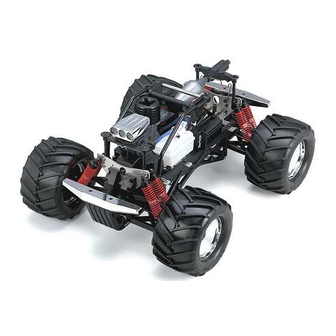
GIGA CRUSHER DF
1/8 SCALE RADIO CONTROLLED .26 X 2 ENGINE POWERED MONSTER TRUCK
GIGA CRUSHER SF
ギガクラッシャー
シングルフォース
1/8 SCALE RADIO CONTROLLED .26 ENGINE POWERED MONSTER TRUCK
目 次 INDEX
●キットの他にそろえる物
RADIO PREPARATION
●プロポの準備
BEFORE YOU BEGIN
●組立て前の注意
●ランナー付プラパーツ配置図
●本体の組立て (デュアルフォース)
●本体の組立て (シングルフォース)
OPERATING PRECAUTIONS
●走行上の注意
●セッティングガイド
OPERATING YOUR MODEL SAFELY
●取扱いの注意
●分解図 (デュアルフォース)
●分解図 (シングルフォース)
●スペアパーツ・オプションパーツリスト
安全のための注意事項
この無線操縦模型は玩具ではありません!
●この商品は高い性能を発揮するように設計されています。組立てに不慣れな方
は、模型を良く知っている人にアドバイスを受け確実に組立ててください。
●小さい部品があるので、組立て作業は幼児の手がとどかない所で必ずおこなっ
てください。
●動かして楽しむ場所は、万一の事故を考えて安全を確認してから、責任をもっ
てお楽しみください。
●組立てた後も、説明書がいつでも見られるように大切に保管してください。
※製品改良のため、予告なく仕様を変更する場合があります。 *SPECIFICATIONS ARE SUBJECT TO BE CHANGED WITHOUT NOTICE.
© 2004 KYOSHO CORPORATION/禁無断転載複製
R
REQUIRED FOR OPERATION
ARRANGEMENT OF PLASTIC PARTS ON RUNNERS
ASSEMBLY (Dual Force)
ASSEMBLY (Single Force)
ADJUSTMENT
EXPLODED VIEW (Dual Force)
EXPLODED VIEW (Single Force)
SPARE PARTS & OPTIONAL PARTS
INSTRUCTION MANUAL
(Dual Force)
UNDER SAFETY PRECAUTIONS
This radio control model is not a toy!
●First-time builders should seek the advice of experienced modelers before
beginning assembly and if they do not fully understand any part of the
construction.
●Assemble this kit only in places out of children's reach!
●Take enough safety precautions prior to operating this model.
You are responsible for this model's assembly and safe operation!
●Always keep this instruction manual ready at hand for quick
reference, even after completing the assembly.
No. 31142 (Dual force) /
組立/取扱説明書
ギガクラッシャー
デュアルフォース
(Single Force)
2 ∼ 3
4 ∼ 5
6 ∼ 7
8 ∼ 26 / 32 ∼ 34
8 ∼ 21 / 27 ∼ 34
38 ∼ 39 / 42 ∼ 44
40 ∼ 44
45 ∼ 48
No. 31141 (Single Force)
3
35
36
37
Advertisement


Need help?
Do you have a question about the GIGA CRUSHER DF and is the answer not in the manual?
Questions and answers