Dell S6000-ON Getting Started Manual
Open networking (on)
Hide thumbs
Also See for S6000-ON:
- Configuration manual (1080 pages) ,
- Troubleshooting manual (29 pages) ,
- Installation manual (41 pages)

Related Manuals for Dell S6000-ON


Summary of Contents for Dell S6000-ON
- Page 1 Dell Networking S6000-Open Networking (ON) Getting Started Guide Publication Date: April 2014 Regulatory Model: S6000...
- Page 2 Copyright © 2014 Dell Inc. All rights reserved. This product is protected by U.S. and international copyright and intellectual property laws. Dell and the Dell logo are trademarks of Dell Inc. in the United States and/or other jurisdictions. All other marks and names mentioned herein may be trademarks of their respective companies.
-
Page 3: Table Of Contents
....... . After Installing the S6000-ON ..... . -
Page 4: About This Guide
About this Guide This document is intended as a Getting Started Guide to get new systems up and running and ready for configuration. For complete installation and configuration information, refer to Installing the S6000-Open Networking (ON) System About this Guide... - Page 5 About this Guide...
-
Page 6: Introduction
Introduction The S6000-ON is a fully featured switch/router one rack unit (RU) system that you can deploy as a spine, leaf, or top of rack (ToR) device where you require 10Gb and/or 40Gb connections. It contains 32 ports of 40G that you can use to... - Page 7 Introduction...
-
Page 8: Hardware Overview
434 x 460 x 43.5 mm (W x D x H). • 17.09 x 18.11 x 1.71 inches (W x D x H). The S6000-ON has a chassis design with 1280Gbps switching bandwidth as listed below: • 32 port 40G QSFP+ •... -
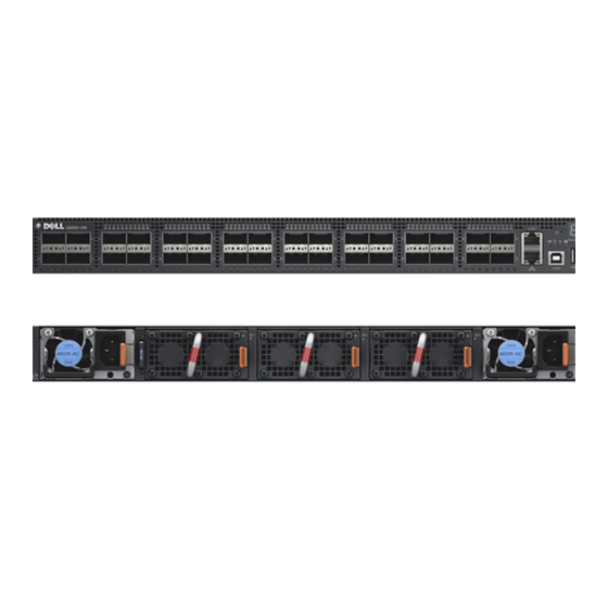
Page 9: I/O Panel
• One RS-232 serial console port • One 10/100/1000BaseT (RJ-45) Ethernet management port Figure 3-1 shows the S6000-ON I/O panel. Figure 3-1. S6000-ON I/O Panel 1 - System LED 2 - Thirty-two QSFP+ Ports 3 - Serial Console 4 - Reset... -
Page 10: Utility Panel
PSUs are required for full redundancy, but the system can operate with a single PSU. NOTE: If you use a single PSU, install a blank plate in the other PSU slot. Dell Networking recommends using power supply 2 (PSU2) as the blank plate slot. -
Page 11: Fans
AC PSU with fan airflow from PSU to I/O All fans and PSUs in a configuration must be in the same airflow direction. The S6000-ON supports three fan trays with airflow directions from I/O to Utility or Utility to I/O. The PSU airflow directions are indicated with stickers on PSUs. - Page 12 As shown in Figure 3-3, the S6000-ON includes LED displays on both the I/O and PSU side of the chassis. Figure 3-3. S6000-ON PSU and Fan Tray LEDs 1- Fan Tray 1-3 LEDs 2 - PSU 1-2 LEDs Hardware Overview...
- Page 13 1 - Serial Console 2 - Master LED 3 - Power LED 4 - Fan Status LED 5 - Locator LED 6 - Stack ID 7 - USB-A 8 - USB-B Console 9 - Management For LED information, refer to your third-party operating software documentation.
-
Page 14: Installation
This section describes the package contents and the steps to unpack the S6000- ON switch. Package Contents When unpacking each switch, make sure that the following items are included: • One S6000-ON switch • One RJ-45 to DB-9 female cable • Two sets of rail kits (no tools required) •... -
Page 15: Installing An Ac Power Supply
PSU and the status LED is at the bottom of the PSU. NOTE: If you use a single PSU, install a blank plate in the other PSU slot. Dell Networking recommends using power supply 2 (PSU2) as the blank plate slot. -
Page 16: Rack Mount The Switch
You may either place the switch on the rack shelf or mount the switch directly into a 19" wide, EIA-310-E-compliant rack (four-post, two-post, or threaded methods). The Dell ReadyRails™ system is provided for 1U front-rack and two-post installations. The ReadyRails system includes two separately packaged rail assemblies and two rails that are shipped attached to the sides of the switch. -
Page 17: Installing The Dell Readyrails System
Do not mount the equipment with the rear panel facing in the downward position. Installing the Dell ReadyRails System The ReadyRails rack mounting system is provided to easily configure your rack so that you can install your switch. Install the ReadyRails system using the 1U tool-less method or one of three possible 1U tooled methods (two-post flush mount, two-post center mount, or four-post threaded). - Page 18 Figure 4-1. 1U Tool-less Configuration 2 Align and seat the front flange pegs in the holes on the front side of the vertical post. Refer to Figure 4-1, item 2. 3 Repeat this procedure for the second rail. 4 To remove each rail, pull on the latch release button on each flange ear and unseat each rail.
- Page 19 Two-Post Flush-Mount Configuration: 1 For this configuration, remove the castings from the front side of each ReadyRails assembly. Refer to Figure 4-2, item 1. Use a Torx driver to remove the two screws from each front flange ear (on the switch side of the rail) and remove each casting.
- Page 20 Two-Post Center-Mount Configuration: 1 Slide the plunger bracket rearward until it clicks into place and secure the bracket to the front post flange with two user-supplied screws. Refer Figure 4-3, item 1. Figure 4-3. Two-Post Center-Mount Configuration 2 Slide the back bracket towards the post and secure it to the post flange with two user-supplied screws.
-
Page 21: Installing The Switch
1U Front-Rack Installation Configure the rails that are attached to the switch. 1 Attach the switch rails (inner chassis members) to the S6000-ON switch. Figure 4-5, item 3 shows the detail for the front standoff with the locking tab. - Page 22 Figure 4-5. Attaching the Switch Rails 2 After you install both switch rails, line them up on the previously mounted Ready-Rails and slide the switch in until it is flush with front of rack. About three inches prior to full insertion, the rail locking feature engages to keep the switch from inadvertently sliding out of the rack and falling.
- Page 23 Figure 4-6. Front Rack Installation Installation...
-
Page 24: Technical Specifications
Technical Specifications Operate the product at an ambient temperature not higher than 40°C. Lithium Battery Caution: There is a danger of explosion if the battery is Replace only with same or equivalent type of battery. incorrectly replaced. Dispose of the batteries according to the manufacturer's instructions. Chassis Physical Design Parameter Specifications... -
Page 25: Power Requirements
Power Requirements Parameter Specifications Power supply 100–240 VAC 50/60 Hz Maximum current draw per system 2.9 A @ 286 watts/100vac 1.4 A @ 286 watts/200vac Maximum power consumption 286 Watts Reliability MTBF 355,178 hours Technical Specifications... - Page 26 Printed in the U.S.A. www.dell.co m | sup po r t.de ll.c om...
Need help?
Do you have a question about the S6000-ON and is the answer not in the manual?
Questions and answers