Advertisement
Table of Contents
Air-Conditioners For Building Application
TECHNICAL & SERVICE MANUAL
Series PEFY
<Indoor unit>
PEFY-P20VMM-E,PEFY-P71VMM-E
Models
PEFY-P25VMM-E,PEFY-P80VMM-E
PEFY-P32VMM-E,PEFY-P100VMM-E
PEFY-P40VMM-E,PEFY-P125VMM-E
PEFY-P50VMM-E,PEFY-P140VMM-E
PEFY-P63VMM-E
INDOOR UNIT
Ceiling Concealed
CONTENTS
SAFETY PRECAUTIONS ·························1
1. FEATURES············································3
2. PART NAMES AND FUNCTIONS ········4
3. SPECIFICATION ···································6
4. OUTLINES AND DIMENSIONS············8
5. WIRING DIAGRAM ·····························10
7. TROUBLE SHOOTING························13
8. DISASSEMBLY PROCEDURE ···········18
For use with R410A & R407C & R22
2004
Advertisement
Table of Contents

Related Manuals for Mitsubishi Electric PEFY-P20VMM-E


Summary of Contents for Mitsubishi Electric PEFY-P20VMM-E
-
Page 1: Table Of Contents
2004 Air-Conditioners For Building Application TECHNICAL & SERVICE MANUAL Ceiling Concealed Series PEFY <Indoor unit> PEFY-P20VMM-E,PEFY-P71VMM-E Models PEFY-P25VMM-E,PEFY-P80VMM-E PEFY-P32VMM-E,PEFY-P100VMM-E PEFY-P40VMM-E,PEFY-P125VMM-E PEFY-P50VMM-E,PEFY-P140VMM-E PEFY-P63VMM-E CONTENTS SAFETY PRECAUTIONS ·························1 1. FEATURES············································3 2. PART NAMES AND FUNCTIONS ········4 3. SPECIFICATION ···································6 4. OUTLINES AND DIMENSIONS············8 5. -
Page 2: Safety Precautions
- Improper installation by the user may result in water leakage, elec- is shorted and operated forcibly, or parts other than those specified tric shock, or fire. by Mitsubishi Electric are used, fire or explosion may result. • Install the air unit at a place that can withstand its weight. - Page 3 Precautions for devices that use R410A or R407C refrigerant Caution: • Do not use the existing refrigerant piping. - The old refrigerant and refrigerator oil in the existing piping con- tains a large amount of chlorine which may cause the refrigerator oil of the new unit to deteriorate.
-
Page 4: Features
FEATURES Ceiling Concealed Series PEFY Indoor unit Cooling capacity/Heating capacity Models PEFY-P20VMM-E 2.2/ 2.5 PEFY-P25VMM-E 2.8/ 3.2 PEFY-P32VMM-E 3.6/ 4.0 PEFY-P40VMM-E 4.5/ 5.0 PEFY-P50VMM-E 5.6/ 6.3 PEFY-P63VMM-E 7.1/ 8.0 PEFY-P71VMM-E 8.0/ 9.0 PEFY-P80VMM-E 9.0/ 10.0 PEFY-P100VMM-E 11.2/ 12.5 PEFY-P125VMM-E 14.0/ 16.0 16.0/ 18.0... -
Page 5: Part Names And Functions
PART NAMES AND FUNCTIONS G Indoor (Main) Unit [In case of bottom inlet] [In case of rear inlet] Air inlet Air inlet Air outlet Air outlet G Remote controller [PAR-20MAA] Once the controls are set, the same operation mode can be repeated by simply pressing the ON/OFF button. - Page 6 G Display CENTRALLY CONTROLLED 1Hr. ON OFF ˚C CLOCK CHECK FILTER CHECK MODE ˚C TEST RUN STAND BY ERROR CODE FUNCTION NOT AVAILABLE DEFROST TEMP. ON/OFF I KL J Current time/Timer Centralized control Timer ON Abnormality occurs Operation mode: COOL, DRY, AUTO, FAN, HEAT...
-
Page 7: Specification
SPECIFICATION 3-1. Specification PEFY-P20 PEFY-P25 PEFY-P32 PEFY-P40 PEFY-P50 Model PEFY-P63 Item VMM-E VMM-E VMM-E VMM-E VMM-E VMM-E 220-240 Voltage Power source Frequency Cooling capacity Note:1 Heating capacity Note:1 0.15 0.22 0.19 0.20 Cooling 0.17 Power consumption 0.15 0.22 Heating 0.19 0.20 0.17 0.73... - Page 8 3-2. Electrical parts specifications Model PEFY-P20 PEFY-P25 PEFY-P32 PEFY-P40 PEFY-P50 PEFY-P63 PEFY-P71 PEFY-P80 PEFY-P100 PEFY-P125 PEFY-P140 Symbol VMM-E VMM-E VMM-E VMM-E VMM-E VMM-E VMM-E VMM-E VMM-E VMM-E VMM-E Parts name Transformer (Primary) 50/60Hz 220-240V (Secondry) (18.4V 1.7A) Room Ω Ω temper ature TH21 Resistance 0˚C/15k...
-
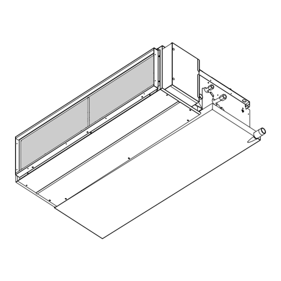
Page 9: Outlines And Dimensions
OUTLINES AND DIMENSIONS Indoor Unit PEFY-P20•25•32•40•50•63•71•80VMM-E Unit : mm... - Page 10 Indoor Unit PEFY-P100•125•140VMM-E Unit : mm...
-
Page 11: Wiring Diagram
WIRING DIAGRAM... -
Page 13: Refrigerant System Diagram
REFRIGERANT SYSTEM DIAGRAM Gas pipe thermistor TH23 Gas pipe Liquid pipe thermistor TH22 Flare connection Heat exchanger Linear expansion valve Strainer (#100mesh) Strainer (#100mesh) Room temparature thermistor TH21 Capacity PEFY-P20,25,32,40VMM-E PEFY-P50VMM-E Item ø 12.7 <1/2F>(R410A) ø Gas pipe 12.7<1/2F> ø 15.88 <5/8F>(R22,R407C) ø... -
Page 14: Trouble Shooting
TROUBLE SHOOTING 7-1. How to check the parts Parts name Check points Room temparature Disconnect the connector, then measure the resistance using a tester. thermistor (TH21) (Sorrounding temperature 10°C~30°C) Liquid pipe thermistor (TH22) Normal Abnormal Gas pipe thermistor (Refer to the thermistor) (TH23) 4.3kΩ~9.6kΩ... -
Page 15: Linear Expansion Valve
<Thermistor Characteristic graph> < Thermistor for lower temperature > Room temparature thermistor(TH21) Thermistor for Liquid pipe thermistor(TH22) lower temperature Gas pipe temparature thermistor(TH23) Drain sensor(DS) =15kΩ ± 3% Thermistor R Fixed number of B=3480kΩ ± 2% Rt=15exp { 3480( 273+t 0˚C 15kΩ... - Page 16 <Output pulse signal and the valve operation> Output Output : 1 ¡ 2 ¡ 3 ¡ 4 ¡ 1 (Phase) Closing a valve Opening a valve : 4 ¡ 3 ¡ 2 ¡ 1 ¡ 4 ø1 The output pulse shifts in above order. ø2 ✻1.
-
Page 17: Function Of Dip-Switch
7-2. FUNCTION OF DIP-SWITCH Operation by switch Switch Pole Function Remarks Thermistor<Intake temperature Indoor unit Built-in remote controller Address board detection>position Filter clogging detection Provided Not provided Filter life 2,500hr 100hr Air intake Effective Not effective Remote indication switching Thermostat ON signal indication Fan output indication Mode Humidifier control Operational while the heat is ON... - Page 18 Switch Pole Operation by switch Remarks Factory setting is for use under an external static pressure of 50Pa, Address board no switch operation is needed when using under the standard condition. 100Pa Option 50Pa 30Pa Note:1 *This switch is for only P20~P80 type. Address board Option Option...
-
Page 19: Disassembly Procedure
DISASSEMBLY PROCEDURE Be careful on removing heavy parts. 8-1. CONTROL BOX OPERATING PROCEDURE PHOTOS 1.Removing the control box cover fig.1 (1) Remo ve the covers two fixing screws (A) and remove the cover. 2.Re-fit (1) Re-fit in reverse order, be sure not to catch wires when re-fitting. - Page 20 Be careful on removing heavy parts. 8-3. THERMISTOR (Intake air temperature detection) OPERATING PROCEDURE PHOTOS 1.Removing the thermistor and thermistor holder fig.1 (1) Pull out the thermistor holder (C) and thermistor (D). 2.Re-fit (1) Re-fit in reverse order. (C),(D) fig.2 View from the opposite side.
- Page 21 Be careful on removing heavy parts. 8-5. THERMISTOR (GAS piping temperature detection) OPERATING PROCEDURE PHOTOS 1.Remove the drainpan with procedure 8-4 fig.1 2.Removing the bottom plate 2 (1) Remove the fixing screws (seven) of the bottom plate 2 (F) and remove plate. fig.1. 3.Removing the thermistor (1) Remove the thermistor (G) from the thermistor holder (H) which is installed on the copper tube.
-
Page 22: Heat Exchanger
Be careful on removing heavy parts. OPERATING PROCEDURE PHOTOS 3.Removing the fan casing and sirocco fan fig.3 (1) Remove the fan casing fixing screws (four for each fan). (2) Remove the fan motor shaft fixing screw (one for each fan) and remove the fan casing and sirocco fan. - Page 24 HEAD OFFICE: MITSUBISHI DENKI BLDG., 2-2-3, MARUNOUCHI, CHIYODA-KU, TOKYO 100-8310, JAPAN Issued in April 2004 MEE03K223 New publication effective April 2004. Printed in Japan Specifications subject to change without notice.
Need help?
Do you have a question about the PEFY-P20VMM-E and is the answer not in the manual?
Questions and answers