Table of Contents
Advertisement
Quick Links
Air-Conditioners For Building Application
TECHNICAL & SERVICE MANUAL
Series PEFY
<Indoor unit>
PEFY-P40VMH-A,PEFY-P100VMH-A
Models
PEFY-P50VMH-A,PEFY-P125VMH-A
PEFY-P63VMH-A,PEFY-P140VMH-A
PEFY-P71VMH-A,PEFY-P200VMH-A
PEFY-P80VMH-A,PEFY-P250VMH-A
INDOOR UNIT
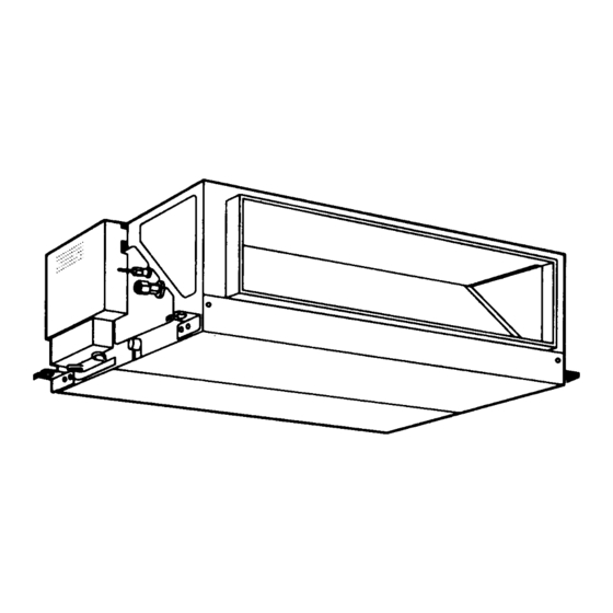
Ceiling Concealed
2001
CONTENTS
SAFETY PRECAUTIONS ·························1
1. FEATURES············································3
2. PART NAMES AND FUNCTIONS ········4
3. SPECIFICATION ···································6
4. OUTLINES AND DIMENSIONS············9
5. WIRING DIAGRAM ·····························11
7. TROUBLE SHOOTING························14
8. DISASSEMBLY PROCEDURE ···········17
Advertisement
Table of Contents

Subscribe to Our Youtube Channel
Related Manuals for Mitsubishi Electric PEFY-P40VMH-A


Summary of Contents for Mitsubishi Electric PEFY-P40VMH-A
-
Page 1: Table Of Contents
2001 Air-Conditioners For Building Application TECHNICAL & SERVICE MANUAL Ceiling Concealed Series PEFY <Indoor unit> PEFY-P40VMH-A,PEFY-P100VMH-A Models PEFY-P50VMH-A,PEFY-P125VMH-A PEFY-P63VMH-A,PEFY-P140VMH-A PEFY-P71VMH-A,PEFY-P200VMH-A PEFY-P80VMH-A,PEFY-P250VMH-A CONTENTS SAFETY PRECAUTIONS ·························1 1. FEATURES············································3 2. PART NAMES AND FUNCTIONS ········4 3. SPECIFICATION ···································6 4. OUTLINES AND DIMENSIONS············9 5. -
Page 2: Safety Precautions
• Install the air unit at a place that can withstand its weight. by Mitsubishi Electric are used, fire or explosion may result. - Inadequate strength may cause the unit to fall down, resulting in injuries. - Page 3 Precautions for devices that use R407C refrigerant Caution: • Do not use the existing refrigerant piping. - The old refrigerant and refrigerator oil in the existing piping con- tains a large amount of chlorine which may cause the refrigerator oil of the new unit to deteriorate. •...
-
Page 4: Features
FEATURES Ceiling Concealed Series PEFY Indoor unit Cooling capacity/Heating capacity Models PEFY-P40VMH-A 4.5/5.0 PEFY-P50VMH-A 5.6/6.3 PEFY-P63VMH-A 7.1/8.0 PEFY-P71VMH-A 8.0/9.0 PEFY-P80VMH-A 9.0/10.0 PEFY-P100VMH-A 11.2/12.5 PEFY-P125VMH-A 14.0/16.0 PEFY-P140VMH-A 16.0/18.0 PEFY-P200VMH-A 22.4/25.0 PEFY-P250VMH-A 28.0/31.5... -
Page 5: Part Names And Functions
PART NAMES AND FUNCTIONS Indoor (Main) Unit Air outlet Air inlet Remote controller [PAR-20MAA] Once the controls are set, the same operation mode can be repeated by simply pressing the ON/OFF button. Operation buttons CENTRALLY CONTROLLED 1Hr. ON OFF ˚C CLOCK CHECK FILTER... - Page 6 Display CENTRALLY CONTROLLED 1Hr. ON OFF ˚C CLOCK CHECK FILTER CHECK MODE ˚C TEST RUN STAND BY ERROR CODE FUNCTION NOT AVAILABLE DEFROST TEMP. ON/OFF I KL J Current time/Timer Centralized control Timer ON Abnormality occurs Operation mode: COOL, DRY, AUTO, FAN, HEAT...
-
Page 7: Specification
SPECIFICATION 3-1. Specification PEFY-P40VMH-A PEFY-P50VMH-A PEFY-P71VMH-A Model PEFY-P63VMH-A Power source 220-240V 50Hz /60Hz Cooling capacity Heating capacity Cooling Power consumption 0.19/0.23 0.24/0.30 0.26/0.33 (50/60Hz) Heating 0.19/0.23 0.24/0.30 0.26/0.33 Cooling 0.88/1.06 1.12/1.38 1.20/1.51 Current Heating 0.88/1.06 1.12/1.38 1.20/1.51 External finish Galvanizing... -
Page 8: Pefy-P140Vmh-A
PEFY-P140VMH-A Model PEFY-P80VMH-A PEFY-P100VMH-A PEFY-P125VMH-A Power source 220-240V 50Hz /60Hz Cooling capacity 11.2 14.0 16.0 18.0 Heating capacity 10.0 12.5 16.0 Cooling Power consumption 0.32/0.40 0.48/0.58 0.48/0.59 (50/60Hz) Heating 0.32/0.40 0.48/0.58 0.48/0.59 Cooling 1.47/1.83 2.34/2.66 2.35/2.70 Current Heating 1.47/1.83 2.34/2.66 2.35/2.70 External finish Galvanizing... - Page 9 3-2. Electrical parts specifications Model PEFY- PEFY- PEFY- PEFY- PEFY- PEFY- PEFY- PEFY- PEFY- PEFY- Symbol P40VMH-A P50VMH-A P63VMH-A P71VMH-A P80VMH-A P100VMH-A P125VMH-A P140VMH-A P200VMH-A P250VMH-A Parts name Tranrsformer (Primary) 50/60Hz 220-240V (Secondry) (23.5V 0.9A) Room TH21 Resistance 0˚C/15kW,10˚C/9.6kW,20˚C/6.3kW,25˚C/5.4kW,30˚C/4.3kW,40˚C/3.0kW temperature thermistor Liquid pipe TH22...
-
Page 10: Outlines And Dimensions
OUTLINES AND DIMENSIONS Indoor Unit PEFY-P40· 50· 63· 71· 80· 100· 125· 140VMH-A Unit : mm... - Page 11 Indoor Unit PEFY-P200· 250VMH-A Unit : mm...
-
Page 12: Wiring Diagram
WIRING DIAGRAM PEFY-P40·50·63·71·80·100·125·140VMH-A... - Page 13 PEFY-P200· 250VMH-A...
-
Page 14: Refrigerant System Diagram
Gas pipe Liquid pipe thermistor TH22 Flared joints(Type 40~140) Brazed joints(Type 200·250) Heat exchanger Linear expansion valve Strainer (#100mesh) Strainer (#100mesh) Room temperature thermistor TH21 Capacity PEFY-P40VMH-A PEFY -P50,63,71,80VMH-A PEFY-P100,125,140VMH-A Item Gas pipe ø12.7<1/2F> ø15.88<5/8F> ø19.05<3/4F> Liquid pipe ø6.35<1/4F> ø9.52<3/8F>... -
Page 15: Trouble Shooting
TROUBLE SHOOTING 7-1. How to check the parts Parts name Check points Room temperature Disconnect the connector, then measure the resistance using a tester. thermistor (TH21) (Sorrounding temperature 10¡C~30¡C) Liquid pipe thermistor (TH22) Normal Abnormal Gas pipe thermistor (Refer to the thermistor characteristic graph) 4.3k ~9.6k Open or short... - Page 16 7-2. Setting of address switch Make sure that power source is turning off. Indoor unit control board SW 2 S W 3 S W 4 < At delivery (All models)> SW 1 S W 4 < At delivery (All models)> 1 2 3 4 5 6 7 8 9 10 1 2 3 CN82...
- Page 17 7-3. Setting of Dip-switch (at delivery) Models Dip-SW S W3 S W4 S W5 PEFY-P40VMH-A 220V 240V 1 2 3 4 5 6 7 8 910 1 2 3 4 5 6 1 2 3 4 5 6 7 8 910...
-
Page 18: Disassembly Procedure
DISASSEMBLY PROCEDURE Be careful on removing heavy parts. 8-1. CONTROL BOX OPERATING PROCEDURE PHOTOS Models 40~140 1.Removing the control box cover fig.1 (1) Remove the fixing screws (two) of the control box (A), and remove the cover. (Fig. 1) *At this stage, the following servicing is possible. 1 Operation and check of the switches (listed below) which are on the control board. - Page 19 Be careful on removing heavy parts. OPERATING PROCEDURE PHOTOS · Models 200 fig.4 1.Removing the control box cover (1) Remove the fixing screws (four) of the control box cover (C), and remove the cover. (Fig. 4) *At this stage, the following servicing is possible.(Fig. 5) 1 Operation and check of the switches (listed below) which are on the control board.
- Page 20 Be careful on removing heavy parts. 8-2. FAN and FAN MOTOR OPERATING PROCEDURE PHOTOS Models 40~140 fig.1 1.Removing the control box. (1) Remove the control box cover and terminal bed cover with procedure 8-1. (2) Remove the fan motor connectors. (3) Remove the fixing screws (two) of the control box and slide the control box to remove.(Fig.
- Page 21 Be careful on removing heavy parts. OPERATING PROCEDURE PHOTOS (4) Slide the motor (A) with motor base (D) in direction of allow fig.5 . (Fig. 5) Arrow 1 fig.6 Motor (A) Models 100~140 *Motor maintenance procedure is almost 40~80 models procedure.
- Page 22 Be careful on removing heavy parts. OPERATING PROCEDURE PHOTOS Models 200· 250 Control box fig.7 1.Removing the control box. cover 2 (1) Remove the control box cover1 with procedure 8-1. (2) Remove the fixing screws (four) of the control cover 2, and remove the control cover2.
- Page 23 Be careful on removing heavy parts. OPERATING PROCEDURE PHOTOS (3) After removing the fixing screws (H)(as shown models fig.11 100~140) of the front fan case(B) and remove the fan. Pull the fan case (B). (4) Remove the fixing screws (K)(three) of the bell mouse (J) attached fan case (L), and remove the bell mouse (J).
- Page 24 Be careful on removing heavy parts. 8-3. LEV,THERMISTOR (Liquid/Gas piping temperature detection) OPERATING PROCEDURE PHOTOS Models 40~140 fig.1 1.Removing the LEV. (1) Remove the control box cover with procedure 8-1. (2) Remove the fixing screws (four) of the heat exchanger cover (A), and remove the cover (A).(Fig.
- Page 25 Be careful on removing heavy parts. 8-4. HEAT EXCHANGER OPERATING PROCEDURE PHOTOS Models 40~140 fig.1 1.Removing the heat exchanger. (1) Remove the heat exchanger cover with procedure 8-3-1. Bottom plate (2) Remove the bottom plate which is air outlet side.(fixing screws : ten) (Fig.
- Page 26 Be careful on removing heavy parts. OPERATING PROCEDURE PHOTOS (4) Remove the maintenance cover.(fixing screws : two) (Fig. 4) fig.4 (5) Remove the heat exchanger.(fixing screws : four) (Fig. 3,5) *Removerd heat exchanger is as shown fig .6 Maintenance cover Fixing screws fig.5 Fixing screws...
- Page 27 Be careful on removing heavy parts. OPERATING PROCEDURE PHOTOS · Models 200 fig.7 1.Removing the heat exchanger. (1) Remove the refrigerant piping and drain hose from main Bottom plate unit.(Be care that water is not leaking from drain hose. ) (2) Remove the power supply wire and the transmission line.
- Page 28 Be careful on removing heavy parts. OPERATING PROCEDURE PHOTOS (7) Remove the fixing screws (three) of the heat exchanger fig.10 cover, and remove the cover. Remove the fixing screws (four) of the maintenance cover, and remove the cover. (Fig. Fixing screws (7) Remove the heat exchanger.
- Page 29 8-5. CONTROL BOX INSIDE LAYOUT Models 40~140 Trans Condenser (for motor) Indoor unit FAN2 CN3T STR2012 FAN3 contoller board DSA board CN52 CN81 CN60 CN27 CN62 CN82 SW14 SW12 SW11 Transmission terminal bed Power sourse Address board terminal bed Models 200· 250 Magnet contactor Trans FAN2...
- Page 30 8-6. SENSOR POSITION PEFY-P40VMH-A PEFY-P50· 63VMH-A Liquid sensor Liquid sensor Gas sensor Gas sensor PEFY-P71· 80VMH-A PEFY-P100· 125VMH-A Gas sensor(100) Liquid sensor Liquid sensor Gas sensor(125) Gas sensor PEFY-P140VMH-A PEFY-P200· 250VMH-A Liquid sensor Liquid sensor( 200·250) Gas sensor(200) Gas sensor...
- Page 32 HEAD OFFICE: MITSUBISHI DENKI BLDG., 2-2-3, MARUNOUCHI, CHIYODA-KU, TOKYO 100-8310, JAPAN Issued in May. 2001 MEE01K051 New publication, effective May. 2001 Printed in Japan Specifications subject to change without notice...
Need help?
Do you have a question about the PEFY-P40VMH-A and is the answer not in the manual?
Questions and answers