
Subscribe to Our Youtube Channel
Related Manuals for SCHOLTES PMG41DCDRSF


Summary of Contents for SCHOLTES PMG41DCDRSF
-
Page 1: Service Information
5413143 Issue 1 Oct. 2010 38 cm GAS HOBS Models Comm. Covered Code Single Ring PMG41DCDRSF 57506 2 Ring PMG42SF 57507 Service Information Scholtès UK © 2010 Reg. Office: Peterborough PE2 9JB Registered in London: 106725... -
Page 2: Table Of Contents
SAFETY NOTES & GENERAL SERVICING ADVICE 1. All Gas Appliances MUST by law be installed by a competent person. Only use a Gas Safe (Corgi in Northern Ireland) Registered Engineer. Service or repairs should always be carried out by Scholtès UK Service personnel. -
Page 3: Introduction
The above 38 cm Domino Gas Hobs were introduced to the Scholtès range during October 2010. Model PMG41DCDRSF is a single Double Crown Wok burner gas hob, model PMG42SF is a double burner gas hob with one Triple Crown burner. Both models have automatic ignition, cast iron pan supports and FSD fitted on each burner. - Page 4 BURNER INPUT RATES & INJECTOR SIZES Table 1 Liquid gas Natural gas Diameter Thermal power By-pass Injector Flow * Injector Flow* (mm) kW (H.s.*) 1/100 1/100 1/100 BURNER Nomin. Reduc. (mm) (mm) (mm) D. Triple Ring 3.25 A. Auxiliary 1.00 I.
-
Page 5: Disposal
DIRECTIVES This model conforms with the following European Economic Community directives: - 2006/95/EEC dated 12/12/06 (Low Voltage) and subsequent amendments; - 2004/108/EEC dated 15/12/04 (Electromagnetic Compatibility) and subsequent amendments; - 93/68/EEC dated 22/07/93 and subsequent amendments; - 2009/142/EEC dated 30/11/09 (Gas) and subsequent amendments; - 2002/96/EC and subsequent amendments. -
Page 6: Installation Instructions
INSTALLATION INSTRUCTIONS Prior to installation, ensure that the local distributions (nature of the gas and gas pressure) and the adjustment conditions are compatible. The adjustment conditions for this appliance are stated on the data badge which is fitted on the underside of the base panel. The appliance is not designed to be connected to a combustion products evacuation device. - Page 7 These hobs are designed to fit into a worktop and base unit(s) with a cut-out as shown in Fig. 1. Fig. 1 PMG42SF Gas Inlet PMG41DCDRSF Service Manual UK English 7 of 13...
- Page 8 Any obstruction such as supports or side panels, must be removed to allow 15 mm minimum depth below the base of the gas hob. Any overhead surface of combustible material must not be closer than 650 mm. See Fig. 2 and Fig. 3. It is recommended that the hob be installed at a distance of at least 55 mm from the rear wall or other vertical surfaces to ensure that the air circulated properly over the cooking area and to avoid overheating the surrounding surfaces.
- Page 9 INSTALLATION - ELECTRICAL REQUIREMENTS WARNING - REFER TO THE RATING PLATE FOR VOLTAGE AND CHECK THAT THE APPLIANCE VOLTAGE CORRESPONDS WITH THE SUPPLY VOLTAGE. THIS APPLIANCE MUST BE EARTHED. CONNECT TO A 230-240V 50Hz SUPPLY ONLY When connected to a B.S. 1363 fused plug, a 3 amp fuse must be fitted. IMPORTANT: The wires in the mains lead fitted to this appliance may not correspond with the coloured marking identifying the terminals in the plug.
-
Page 10: Description Of The Appliance
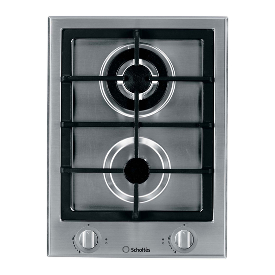
DESCRIPTION OF THE APPLIANCE OVERALL VIEW - PMG42 shown Support Grid for COOKWARE GAS BURNERS Control Knobs for GAS BURNERS SAFETY Ignition for DEVICES GAS BURNERS • GAS BURNERS differ in size and power. Use the diameter of the cookware to choose the most appropriate burner to cook with. -
Page 11: Dismantling Procedure
DISMANTLING PROCEDURE WARNING A gas tightness test must be carried out, both before and after completion of any work involving installation, disconnection, removal, alteration and replacement or maintenance of any gas appliance, fitting, etc. ii) Before continuing, ensure that the appliance is disconnected from the electrical supply, and before servicing any gas carrying component, disconnect the gas supply to the appliance. - Page 12 THERMOCOUPLES Remove the hob top as in (1). Undo the 15 mm union nut. Remove the 2 screws in the burner base. When loose, this will allow access to the 8 mm nut holding the thermocouple plate. Reassemble in reverse order. TO REMOVE THE HOB ELECTRODES &...
-
Page 13: Wiring Diagram
WIRING DIAGRAM Spark Generator Transformer Microswitch Terminal Block 22 Brown 66 Light Blue 5413143wd.pdf 230V~50Hz 15 Yellow/Green PMG41 / PMG42 Service Manual UK English 13 of 13...
Need help?
Do you have a question about the PMG41DCDRSF and is the answer not in the manual?
Questions and answers