
Subscribe to Our Youtube Channel
Related Manuals for SCHOLTES PMI42.1SF


Summary of Contents for SCHOLTES PMI42.1SF
- Page 1 5413204 Issue 1 March 2011 TOUCH CONTROL INDUCTION 2 PLATES Model Comm. Covered Code PMI42.1SF 64263 Service Information Scholtès UK © 2011 Reg. Office: Peterborough PE2 9JB Registered in London: 106725...
- Page 2 SAFETY NOTES & GENERAL SERVICING ADVICE 1. This manual is NOT intended as a comprehensive repair/maintenance guide to the appliance. 2. It should ONLY be used by suitably qualified persons having technical competence applicable product knowledge and suitable tools and test equipment. 3.
-
Page 3: Table Of Contents
INDEX Introduction ............4 Technical Specifications . -
Page 4: Introduction
INTRODUCTION OF THE SCHOLTÈS TOUCH CONTROL HOB PMI42.1SF This model was introduced into the Scholtès range during November 2010. Model No. Commercial Code Colour PMI42.1SF 64263 Black ceramic glass with stainless steel profile TECHNICAL SPECIFICATIONS General Touch control with 9 heat settings... -
Page 5: Safety Information
SAFETY INFORMATION Never • Never leave children unsupervised where a cooking appliance is installed as all surfaces will be hot during and even after its use. • Never allow anyone to sit or stand on any part of the appliance. •... -
Page 6: Advice & Recommendations
ADVICE & RECOMMENDATIONS • This appliance was designed for non- • Certain fundamental rules must be followed professional, household use. when using electrical appliances. • Before using the appliance, read the instructions The following are of particular importance: in the owner’s manual carefully since it contains •... -
Page 7: Installation
INSTALLATION INFORMATION Taken from the Instructions for Installation and Use The following instructions are intended for a qualified installer so that the installation and maintenance procedures may be followed in the most professional and expert manner possible. Important: Unplug the electrical connection before performing any maintenance or regulation upkeep work. - Page 8 Front Induction 50 MIN. aria - air - air - Luft - aire - lucht - ar induzione - induction - induction - Induktion 100 cm MIN. Induction - inducción - inductie - indução (2 x 500) ZONA FORNO O ARMADIETTO OVEN ZONE OR OVEN ZONE OR CUPBOARD CUPBOARD...
-
Page 9: Controls
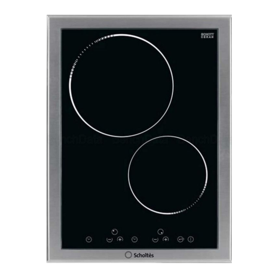
CONTROLS Fig.3 PMI 42.1 SF 1. cooking zone Ø 160/1400W 2. cooking zone Ø 200/2300W 1. On/Off 2. Child safety (key lock) 3. Cooking zone indication 4. Power increase 5. Power Decrease 6. Timer/a 7. Timer/b 8. Timer Led 9. Key lock Led 3a 4 Service Manual UK English... -
Page 10: Operation
OPERATION Operating Principle - Fig. 4 It exploits the electromagnetic properties of most cooking Fig. 4 vessels. The coil (inductor) which produces the electromagnetic field is operated and controlled by the electronic circuit. The heat is transmitted to food by the cooking vessel itself. The cooking process takes place as described below: loss of heat is minimum (high efficiency) the system stops automatically when the vessel is... - Page 11 Switching Off a Cooking Zone a) Pressing the '+' and '-' buttons of the desired cooking zone at the same time. b) Selecting cooking level '0' of the desired cooking zone with the '-' button. If the last cooking zone is switched off, the control switches to the OFF mode after 10 seconds if nothing else is switched on.
- Page 12 Setting of the Timer Value Following the selection of the time, the related LED flashes as described above. The countdown time of the desired timer can be set by means of the +/- buttons. Starting with the plus button, the first value displayed is '01' and progressively increases from 1 to a maximum value of '99' (upper limit).
- Page 13 Key Lock (Child Safety) Locking/Unlocking of the Key Lock The keypad is blocked when the Key Lock button is pressed in the Stand-by or On mode; the Key-Lock LED '9' lights permanently. The control continues to operate in the previously set mode but can no longer be controlled by other buttons, except by the Key-Lock button or the ON/OFF button.
- Page 14 Cooking Vessels (Fig. 5) Fig. 5 a magnet attracting vessel may be a suitable vessel for induction cooking. prefer vessels which are especially declared to be suitable for induction cooking. flat and thick bottomed vessels. a vessel with a 20 cm diameter ensures the maximum exploitation of power, a smaller vessel reduces power exploitation, but does not cause any energy loss.
-
Page 15: Fault Codes
FAULT CODES General Errors Priority Display Description Lag Time System Blind connection of control. Directly located at radiant U400 1 sec heating element or reported via LIN (induction) Er31 Invalid or no configuration available 1 sec Induction Interference on LIN Bus. A necessary participant does Er47 1 sec Induction... -
Page 16: Induction Heaters
The detection and prioitisation of most errors occurring with a cooking zone is carried out by the induction sub-assembly. This is also responsible for the lag time of an error. Adding to this, the communication period via LIN Bus is to be taken into account until the error is eventually indicated on the TC. -
Page 17: Servicing & Dismantling Procedure
SERVICING & DISMANTLING INSTRUCTIONS Safety Notes Refer to the Safety Notes on Page 2 of this manual. Before carrying out any work, ensure that the appliance is disconnected from the mains supply. Personal safety precautions must be taken to protect against accidents caused by sharp edges on metal, glass and plastic parts.
Need help?
Do you have a question about the PMI42.1SF and is the answer not in the manual?
Questions and answers