
Summary of Contents for EEG EN 530
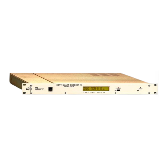
- Page 1 HDTV SMART ENCODER IV MODEL EN 530 EEG Enterprises, Inc. 586 Main Street Farmingdale, New York 11735 TEL: (516) 293-7472 FAX: (516) 293-7417 Copyright (c), EEG Enterprises, Inc. 2000-2007 All rights reserved.
-
Page 2: Table Of Contents
Clone Port Option................33 EN530 Specifications ________________________________________ 34 References ________________________________________________ 36 Copyright 2000-2007, EEG Enterprises, Inc. All rights reserved. The contents of this manual may not be transmitted or reproduced in any form without the written permission of EEG. The revision date for this manual is September 13, 2007. -
Page 3: Introduction
High Definition formats. The Advanced Smart Encoder IV protocol is a superset of the protocol used in earlier industry standard EEG Smart Encoders, ensuring smooth user transition and full software compatibility. All Line 21 functionality of the EN470 Smart Encoder III is preserved in addition to the EN530’s advanced DTVCC operations. -
Page 4: Internal Block Diagram
EN530 HDTV Smart Encoder IV Internal Block Diagram The following diagram depicts the internal processing paths of the EN530: ©2000-2007 EEG Enterprises, Inc. -
Page 5: Installation
Encoder when bypass is set. The LED indicator is off when the Encoder is bypassed. RESET Performs a hardware reset. The Encoder will reboot, all operations will be cleared, and status will return to the default settings stored in Non-Volatile Memory. ©2000-2007 EEG Enterprises, Inc. - Page 6 SD-SDI IN, and the bottom row will display HD if a video source is present at the HD-SDI IN. If an SDI signal is connected to HD-SDI IN for SDI VANC encoding, the HD indicator will appear. ©2000-2007 EEG Enterprises, Inc.
-
Page 7: Rear Panel
ATSC encoder. Configuration of this port is described in Section 3 under the “HD Output Types” heading. General purpose serial data port for caption or XDS input. Configurable for RS232 or RS422 operation. ©2000-2007 EEG Enterprises, Inc. - Page 8 ENCODER ON bypass. HD-SDI/SDI Out VANC data encoded HD-SDI SMPTE 292M video output. OUT 1 is the primary output. OUT 2 is for monitoring or other secondary use. Only OUT 1 is affected by ENCODER ON bypass. ©2000-2007 EEG Enterprises, Inc.
-
Page 9: Data Port Settings
MA is Off Hook and begins a data entry mode for a service, only P3 may preempt the modem and take over data entry for that service. MA will retain this priority until either P3 takes over or the modem returns On Hook. ©2000-2007 EEG Enterprises, Inc. -
Page 10: Encoder Operation
Command Format The EN530 command set is an extension of the industry standard Smart Encoder command set used in the EEG 470 series encoders. Most commands in the EN530 command set can be entered through any serial input port or through the dial-up modem;... -
Page 11: Hd Output Types
Entering 0 as the Line parameter will set insertion for the first available VANC line, using the order listed in the table below for each format. In interlaced formats, caption data will only be inserted once per frame, in the first field. ©2000-2007 EEG Enterprises, Inc. - Page 12 Grand Alliance is a “push” protocol; the EN530 sends data out through P1 as it becomes available, and the ATSC encoder synchronizes the data upon reception. The Grand Alliance transport protocol in use by EEG equipment is described on page 31 of this manual.
-
Page 13: Local Caption Entry
The use of local entry modes is completely independent from the HD output type, which for any of the entry modes described may be either insertion onto the HD video output or serial output to an ATSC encoder. ©2000-2007 EEG Enterprises, Inc. - Page 14 HD video input is down-converted and encoded to the SD video output. The default down-conversion setting varies based on the firmware version of your Encoder. Enter the command without a parameter to check the current setting. ©2000-2007 EEG Enterprises, Inc.
- Page 15 3 Control pairs are corrected for proper alignment and doubled in Field 1. 4 Field 1 default. Control pairs are corrected for proper alignment, doubled in Field 1, and non-Line 21 codes are omitted. ©2000-2007 EEG Enterprises, Inc.
- Page 16 (top of the screen) to b15 (bottom of the screen). The default value is b15. Always set the Base value at least as large as the number of rows in the rollup display, or else the uppermost row(s) of the display will not be visible. ©2000-2007 EEG Enterprises, Inc.
-
Page 17: Xds Insertion
Volatile Memory and inserted automatically whenever the Encoder is operating. Packets are inserted into output video signals using EEG’s proprietary Stochastic Scheduling Algorithm. The Stochastic Scheduling Algorithm is a finely tuned solution to the Field 2 bandwidth limitations that cause difficulties in XDS packet transmission. - Page 18 Content sets the information content of the packet. Content can be entered in ASCII text enclosed in curly braces, { }, or in ASCII Hex notation. A checksum need not be enclosed, as the Encoder will calculate it automatically before insertion. ©2000-2007 EEG Enterprises, Inc.
- Page 19 <CTRL+A>P L105 –1 4840 <ENTER> will create a default program rating packet of None. This packet will be inserted beginning 5 minutes after an interruption in upstream program rating data, and will continue to be transmitted indefinitely until upstream data resumes. ©2000-2007 EEG Enterprises, Inc.
- Page 20 Source indicates whether the packet is locally inserted (Loc) or upstream regenerated (Up). A report on an individual packet includes the packet’s hex byte representation, decoded content for common packets, and checksum in addition to the above information. ©2000-2007 EEG Enterprises, Inc.
- Page 21 Omitting the Class parameter will cause the block/pass status for each Class to be reported. Example: <CTRL+A>T –0100 <ENTER> blocks all upstream XDS packets in the Current Program Class. <CTRL+A>T 0100 <ENTER> will resume normal XDS operation. ©2000-2007 EEG Enterprises, Inc.
-
Page 22: Url And Text Encoding
The default setting is Delete. O/H instructs the Encoder to either Output the article to the appropriate channel queue immediately or to Hold it in memory for future use. Immediate output is the default setting. ©2000-2007 EEG Enterprises, Inc. - Page 23 The default setting is Last. Example: <CTRL+A>0 EEG_URL T2 3 D O N <ENTER> EEG on the Web <ENTER> <http://www.eegent.com>[t:p][C510]<ENTER> <CTRL+C> will create a two line message that displays and identifies a URL address. The use of brackets, attributes, and checksum is per EIA-608B specification.
- Page 24 When the list is completed, enter the End Set Output Queue command. A message that is associated with a different channel cannot be added to the queue. Display Output Queue <CTRL+A>B <ENTER> Displays the contents of both text channel output queues. ©2000-2007 EEG Enterprises, Inc.
-
Page 25: Additional Features
Deletes the command with the specified list number from NVM. The remaining commands in the list will be renumbered to fill the empty list number left by a deletion. If “-a” is specified as the list number, all commands in NVM will be deleted. ©2000-2007 EEG Enterprises, Inc. - Page 26 Returns a list of messages stored in the Encoder’s PROM. The PROM may store up to 8 factory configured commands that execute upon power up or reset. If PROM commands are present, they are executed before NVM commands. ©2000-2007 EEG Enterprises, Inc.
-
Page 27: Serial Port Configuration
The rear panel serial port connectors have six contacts each. The pin assignments for each port and configuration are shown in the following table. 1→ 6 P1-3, P1-3, MA, MB RS232 RS422 Telco (VTR) Switch 4 Ground Common Switch 3 Switch 2 Ground Common Switch 1 Ground ©2000-2007 EEG Enterprises, Inc. -
Page 28: Gpi Switch Functions
Activating this function disables P2 for data input. Users connected to P2 will not be able to enter any caption data, and if a user is inputting data and then the switch is closed, the user will be booted out of data input mode. ©2000-2007 EEG Enterprises, Inc. - Page 29 To place the above command in NVM so that the encoder will automatically power up in the mode described in the example above, you would enter: <CTRL+A>w p1 <CTRL+A>R – b3 t2 - <ENTER> ©2000-2007 EEG Enterprises, Inc.
-
Page 30: Encoder Status Commands
OFF indicates that the channel has been turned off (see page 13) and incoming data is being ignored. SD Video Presence <CTRL+A>b <ENTER> Reports either Video Present or No Video Present to indicate whether or not the Encoder is receiving an SD video signal. ©2000-2007 EEG Enterprises, Inc. - Page 31 <CTRL+C> Monitors and displays the EIA-608B caption data encoded in the specified channel. The I/O parameter determines whether the incoming (enter as I) or outgoing (O) data is monitored. The default settings are incoming and CC1. ©2000-2007 EEG Enterprises, Inc.
-
Page 32: Appendices
Appendices Appendix A: Grand Alliance Interface Protocol The following table describes the Data Packet Structure used by EEG equipment to send caption data to Grand Alliance protocol ATSC encoders. This protocol has been proven compatible with encoders from all major manufacturers supporting GA protocol. -
Page 33: Rs422 Configuration
2 & 3. All jumpers in both the A and B headers for each port must have the same setting; thus, a total of four jumpers per port must be switched for a correct reconfiguration. ©2000-2007 EEG Enterprises, Inc. -
Page 34: Clone Port Option
On a Clone port enabled Encoder, Clone port will be automatically toggled On each time the unit is power cycled. Note that P2 will not respond to input commands when Clone port is toggled on. ©2000-2007 EEG Enterprises, Inc. -
Page 35: En530 Specifications
Output Impedance 75 Ohms Output Level 800 mV p-p ± 10% DC Offset 0V ± 0.5V Rise/Fall Time 470pS nominal Overshoot < 10% of amplitude Output Return Loss >= 18dB, 1-270 MHz Output Jitter < 300 pS ©2000-2007 EEG Enterprises, Inc. - Page 36 Line Current 0.3 A maximum Input Power 36 W Circuit Protection Internal to On/Off switch, 0.4 A EMI/RFI Complies with FCC Part 15 Class A, EU EMC Directive OPTIONS EN-SLIDE Rack Slides EN-TCR LTC Time Code Reader ©2000-2007 EEG Enterprises, Inc.
-
Page 37: References
SMPTE 291M, Ancillary Data Packet and Space Formatting, 1998. SMPTE 292M, Bit-Serial Digital Interface for High Definition Television Systems, 1998. SMPTE 333M, DTV Closed Caption Server to Encoder Interface, 1999. SMPTE 334M, Vertical Ancillary Data Mapping for Bit-Serial Interface, 2000. ©2000-2007 EEG Enterprises, Inc.
Need help?
Do you have a question about the EN 530 and is the answer not in the manual?
Questions and answers