Sign In
Upload
Manuals
Brands
Yamaha Manuals
Controller
SRCP
Yamaha SRCP Manuals
Manuals and User Guides for Yamaha SRCP. We have
3
Yamaha SRCP manuals available for free PDF download: User Manual
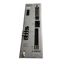
Yamaha SRCP User Manual (246 pages)
Single-axis Robot Controller
Brand:
Yamaha
| Category:
Controller
| Size: 1.76 MB
Table of Contents
Table of Contents
3
Chapter 1 OVERVIEW
9
Features of the SRCP Series Controller
10
Setting up for Operation
11
External View and Part Names
12
SRCP Controller
12
Tpb
15
System Configuration
16
Accessories and Options
17
Accessories
17
Peripheral Options
17
Chapter 2 INSTALLATION and CONNECTION
19
Installing the SRCP Controller
20
Installation Method
20
Installation Location
20
Connecting the Power Supply
21
Power Supply
21
Installing an External Leakage Breaker
22
Installing a Circuit Protector
22
Installing Current Control Switches
23
Insulation Resistance and Voltage Breakdown Tests
23
Grounding
23
Connecting the SRCP to the Control Unit
23
Connecting to the Robot
24
Robot I/O Connector and Signal Table
24
Motor Connector and Signal Table
24
Connecting to the I/O. CN Connector
25
Connecting to the EXT. CN Connector
26
Connecting to the Regenerative Unit
27
Chapter 3 I/O INTERFACE
29
I/O Signals
30
I/O. CN Connector Signals
30
EXT. CN Connector Signals
30
Input Signal Description
31
Dedicated Command Input
31
General-Purpose Input (DI0 to DI7)
34
SERVICE Mode Input (SVCE)
35
Interlock (LOCK)
35
Emergency Stop Inputs 1, 2 (EMG1, EMG2)
35
Output Signal Description
36
Dedicated Output
36
General-Purpose Output (DO0 to DO4)
37
Feedback Pulse Output
37
I/O Circuits
38
I/O Circuit Specifications
38
I/O Circuit and Connection Example
39
I/O Connection Diagram
40
Connection to PLC Output Unit
40
Connection to PLC Input Unit
41
I/O Control Timing Charts
42
When Turning the Power on
42
When Executing a Dedicated Input Command
43
When Interlock Signal Is Input
46
When Emergency Stop Is Input
47
When Alarm Is Issued
47
When Executing a Point Movement Command
48
Chapter 4 BASIC OPERATION of the TPB
49
Connecting and Disconnecting the TPB
50
Connecting the TPB to the SRCP Controller
50
Disconnecting the TPB from the SRCP Controller
51
Basic Key Operation
52
Reading the Screen
53
Program Execution Screen
53
Program Edit Screen
53
Point Edit Screen (Teaching Playback)
54
DIO Monitor Screen
54
Hierarchical Menu Structure
55
Restricting Key Operation by Access Level
56
Explanation of Access Level
56
Changing an Access Level
57
Chapter 5 PARAMETERS
59
Setting the Parameters
60
Parameter Description
61
Chapter 6 PROGRAMMING
75
Basic Contents
76
Robot Language and Point Data
76
Using the TPB to Enter the Robot Language
76
Program Specifications
76
Editing Programs
77
Creating Programs after Initialization
78
Creating a New Program
80
Adding a Step
81
Correcting a Step
83
Inserting a Step
84
Deleting a Step
85
Program Utility
86
Copying a Program
86
Deleting a Program
87
Viewing the Program Information
88
Chapter 7 EDITING POINT DATA
89
Manual Data Input
90
Teaching Playback
91
Direct Teaching
93
Manual Control of General-Purpose Output
95
Manual Release of Holding Brake
96
Deleting Point Data
97
Tracing Points (Moving to a Registered Data Point)
98
Chapter 8 ROBOT LANGUAGE
99
Robot Language Table
100
Robot Language Syntax Rules
101
Command Statement Format
101
Variables
102
Program Function
103
Multi-Task Function
103
Robot Language Description
104
Mova
104
Movi
104
Movf
105
Jmp
105
Jmpf
106
Jmpb
107
Call
108
Wait
109
Timr
109
Srvo
111
Stop
111
Orgn
112
Ton
113
Toff
113
Jmpp
114
Mat
115
Msel
116
Movm
117
Jmpc
118
Jmpd
118
Csel
119
Shft
121
Sample Programs
122
Moving between Two Points
122
Moving at an Equal Pitch
122
Positioning 2 Points and Sending Job Commands to a PLC at each Position
123
Robot Stands by at P0, and Moves to P1 and then to P2 to Pick and Place a Workpiece
124
Picking up 3 Kinds of Workpieces Flowing on the Front Conveyor and Placing Them on the Next Conveyors While Sorting
125
Switching the Program from I/O
127
Axis Movement and I/O Multi-Task
129
Turning on General-Purpose Outputs During Robot Movement after a Certain Time Has Elapsed
130
Turning on a General-Purpose Output During Robot Movement When It Has Passed a Specified Position
131
Chapter 9 OPERATING the ROBOT
133
Performing Return-To-Origin
134
Using Step Operation
136
Using Automatic Operation
139
Switching the Execution Program
141
Emergency Stop Function
142
Initiating an Emergency Stop
142
Recovering from an Emergency Stop
142
Displaying the Memory I/O Status
144
Displaying the Variables
145
Chapter 10 OTHER OPERATIONS
147
Initialization
148
DIO Monitor Display
150
Display from the Monitor Menu
150
Display from the DIO Key Operation
151
System Information Display
151
SERVICE Mode Function
152
Safety Settings for SERVICE Mode
153
Enabling/Disabling the SERVICE Mode Function
155
Setting the SERVICE Mode Functions
157
System Utilities
159
Viewing Hidden Parameters
159
Using a Memory Card
160
Saving Controller Data to a Memory Card
160
Loading Data from a Memory Card
162
Formatting a Memory Card
164
Viewing the ID Number for Memory Card Data
165
Duty (Load Factor) Monitor
166
Measuring the Duty (Load Factor)
168
Using the Internal Flash ROM
169
Saving the Parameter Data Onto the Flash ROM
170
Manually Loading the Data from Flash ROM
172
Initializing the Flash ROM Data
174
Chapter 11 COMMUNICATION with PC
177
Communication Parameter Specifications
178
Communication Cable Specifications
179
Connecting to the Computer with a 25-Pin D-Sub Connector
179
Connecting to the Computer with a 9-Pin D-Sub Connector
179
Communication Command Specifications
180
Communication Command List
181
Communication Command Description
184
Robot Movements
184
Data Handling
193
Utilities
205
Chapter 12 MESSAGE TABLES
209
Error Messages
210
Error Message Specifications
210
Command Error Message
210
Operation Error Message
211
Program Error Message
212
System Error Message
213
Multi-Task Error Message
213
TPB Error Messages
214
Stop Messages
215
Message Specifications
215
Displaying the Error History
216
Chapter 13 TROUBLESHOOTING
219
If a Trouble Occurs
220
Alarm and Countermeasures
221
Alarm Specifications
221
Alarm Message List
222
Troubleshooting for Specific Symptom
225
Relating to the Robot Movement
225
Relating to the I/O
227
Other
228
Displaying the Alarm History
229
Chapter 14 MAINTENANCE and WARRANTY
231
Warranty
232
Warranty Description
232
Warranty Period
232
Exceptions to the Warranty
232
Replacing the System Backup Battery
233
Updating the System
234
Chapter 15 SPECIFICATIONS
235
SRCP Sereis
236
Basic Specifications
236
Robot Number List
237
LED Display
237
Tpb
238
Basic Specifications
238
Regenerative Unit (RGU-2)
239
Basic Specifications
239
Dimensions
239
Chapter 16 APPENDIX
241
How to Handle Options
242
Memory Card
242
POPCOM Communication Cable
244
Advertisement
Yamaha SRCP User Manual (148 pages)
PROFIBUS NETWORK BOARD
Brand:
Yamaha
| Category:
Network Card
| Size: 0.99 MB
Table of Contents
Table of Contents
5
Cautions to Ensure Safety
7
Basic Safety Points
8
System Design Safety Points
8
Installation and Wiring Safety Points
9
Start-Up and Maintenance Safety Points
10
Precautions When Disposing of the Unit
10
Warranty
10
PROFIBUS Unit
11
PROFIBUS Unit Features
12
PROFIBUS System Concept
13
BROFIBUS Cable Connections
14
Parallel I/O Connector
15
Controller (Slave Station) System Setting
17
Validating the PROFIBUS Unit
17
Setting the Station Address
18
Checking the Communication Speed
19
Sequencer (Master Station) Settings
20
Exchanging Data with the Controller
20
I/O Information
21
Profile (I/O Signal Table)
21
Dedicated Command Inputs
23
General-Purpose Inputs (SI200 - SI231)
27
Interlock (LOCK)
28
Emergency Stop Input (EMG)
28
Service Mode (SVCE)
29
Dedicated Outputs
30
General-Purpose Outputs (SO200 - SO231)
31
Timing Chart
32
Right after Controller Power Turns on
32
Dedicated Input Command Execution
33
When Interlock Signal Is Input
37
When Emergency Stop Signal Is Input
38
When an Alarm Is Issued
39
When Point Movement Commands Are Run
40
I/O Assignment Change Function
41
Changing the I/O Assignment
41
I/O Assignment List
42
I/O Assignment Selection Parameter Description
44
I/O Signal Descripion
46
Timing Chart
51
Robot Language
61
Movf
61
Jmpf
62
Jmpb
63
Wait
64
Emulated Serialization on Parallel DIO
65
Remote Command
67
Remote Command Specifications
67
Remote Command & Status Value List
68
Special Commands
71
Remote Command Details (Robot Operation)
72
Remote Command Details (Data Handling)
106
Remote Command Details (Utilities)
129
Remote Command Details (Special Commands)
133
Status Details
134
Current Position Indication Mode
135
Sending/Receiving Example
136
Other Operations
137
Serial I/O Display
137
Manual Control of General-Purpose Output
140
Error Message
141
Troubleshooting
142
Specifications
144
Supplement
145
GSD Files
145
Yamaha SRCP User Manual (52 pages)
Yamaha Network Board User's Manual
Brand:
Yamaha
| Category:
Network Card
| Size: 1.09 MB
Table of Contents
Table of Contents
5
Chapter 1 Cautions to Ensure Safety
7
Basic Safety Points
8
System Design Safety Points
8
Installation and Wiring Safety Points
9
Start-Up and Maintenance Safety Points
10
Precautions When Disposing of the Unit
10
Warranty
11
Chapter 2 Ethernet Unit
13
Ethernet Unit Features
14
How Data Is Exchanged
15
How to Connect to Ethernet
16
Making System Settings for the Controller (Server)
17
Validating the Ethernet Unit
17
Setting the IP Address
18
Setting the Subnet Mask
20
Setting the Gateway
21
Making the PC Settings (Client)
23
Setting the TCP/IP Protocol
23
Checking the Connection with "Ping
25
Using TELNET
26
Difference between TELNET and RS-232C Communications
26
TELNET Dedicated Parameters
27
TELNET Dedicated Parameters: Setup Method 1
27
TELNET Dedicated Parameters: Setup Method 2
28
Description of TELNET Dedicated Parameters
29
TELENET Communication Commands
31
Communication Command Specifications
31
Ethernet Unit Control Commands
32
Robot Control Commands
32
Making a Connection with TELNET.EXE
33
Other Operating Tasks
35
Displaying the MAC Address
35
Displaying the Version of the Ethernet Unit
36
Message List
37
Error Messages
37
Telnet Message List
37
Troubleshooting
38
Specifications
41
Ethernet Unit Specifications
41
Modular Connector
42
UTP (STP) Cable
43
Supplement
44
Typical Network Systems
44
Description of Terminology
49
Network Board
52
Advertisement
Advertisement
Related Products
Yamaha SRCX-05
Yamaha SRCX-10
Yamaha SRCX-20
Yamaha SRCP30
Yamaha SRCP Series
Yamaha SRCD
Yamaha SRCX
Yamaha SRCD Series
Yamaha SRCX Series
Yamaha SR-C20A
Yamaha Categories
Motorcycle
Musical Instrument
Electronic Keyboard
Receiver
Amplifier
More Yamaha Manuals
Login
Sign In
OR
Sign in with Facebook
Sign in with Google
Upload manual
Upload from disk
Upload from URL