Sign In
Upload
Manuals
Brands
Sun Microsystems Manuals
Desktop
Sun Blade 1000
Sun Microsystems Sun Blade 1000 Manuals
Manuals and User Guides for Sun Microsystems Sun Blade 1000. We have
4
Sun Microsystems Sun Blade 1000 manuals available for free PDF download: Service Manual, Module Installation Manual, Cpu Module Installation Instructions, Manual
Sun Microsystems Sun Blade 1000 Service Manual (342 pages)
Brand:
Sun Microsystems
| Category:
Computer Hardware
| Size: 7.03 MB
Table of Contents
Table of Contents
3
Preface
35
Product Description
41
Product Overview
41
TABLE 1-1 Sun Blade 1000 and Sun Blade 2000 Product Features and Options
42
External Components
44
FIGURE 1-2 Front Panel Overview - Sun Blade 1000 and Sun Blade 2000 Workstations
45
FIGURE 1-3 Back Panel Overview - Sun Blade 1000 and Sun Blade 2000 Workstations
46
TABLE 1-2 Back Panel Overview - Sun Blade 1000 and Sun Blade 2000 Workstations
47
Replaceable Components
48
FIGURE 1-4 Exploded View - Sun Blade 1000 and Sun Blade 2000 Workstations
49
TABLE 1-3 Replaceable Components
50
Sunvts Overview
53
Sunvts Description
53
Sunvts Requirements
54
Sunvts References
54
Power on Self-Test
55
POST Overview
55
How to Use POST
56
Pre-POST Preparation
56
Setting up a TIP Connection
56
FIGURE 3-1 Setting up a TIP Connection
57
Verifying the Baud Rate
58
Setting up POST to Run in an Openboot PROM Environment
58
Maximum and Minimum Levels of POST
59
Diag-Level Variable Set to Max
60
Diag-Level Variable Set to Min
84
POST Progress and Error Reporting
104
Troubleshooting Procedures
105
Power on Failure
106
System Leds
106
TABLE 4-1 Power-Indicator LED States
106
Video Output Failure
107
Frame Buffer Power Management
107
Hard Drive or DVD-ROM Drive Failures
109
Hard Drive or DVD-ROM Read or Parity Errors
109
TABLE 4-2 Internal Drives Identification
109
DVD-ROM Command Errors
110
Power Supply Troubleshooting
110
DIMM Failure
112
Openboot PROM On-Board Diagnostics
112
FIGURE 4-1 Power Supply Connector Jack Location
112
Watch-Clock Diagnostic
113
Watch-Net and Watch-Net-All Diagnostics
113
Probe-SCSI and Probe-SCSI-All Diagnostics
114
Test Alias Name, Device Path, -All Diagnostic
115
Graphics Card
116
TABLE 4-3 Selected Openboot PROM On-Board Diagnostic Tests
116
Openboot Diagnostics
117
Starting the Openbootdiag Menu
118
QLC Diagnostic Output Message
121
Audio Output Message
122
Bbc@1,0 Output Message
122
Ebus@5 Output Message
122
Firewire@5,2 Output Message
123
Flashprom@0,0 Output Message
123
Floppy Output Message
123
Gpio@1,300600 Output Message
124
I2C@1,2E Output Message
124
I2C@1,30 Output Message
125
Network@5,1 Output Message
125
Parallel Port Output Message
125
Pmc@1,300700 Output Message
126
Rtc@1,300070 Output Message
126
Scsi@6 Output Message
126
Scsi@6,1 Output Message
127
Serial Output Message
127
USB Output Message
127
Test-All Output Message
128
Preparing for Component Removal and Replacement
131
Safety Requirements
132
Safety Symbols
132
Safety Precautions
133
Modification to Equipment
133
Placement of a Sun Product
133
Power Cord Connection
133
Electrostatic Discharge
134
Lithium Battery
134
Tools Required
135
Powering off the Workstation
135
Removing the Access Panel
138
FIGURE 5-3 Removing the Access Panel
139
Attaching the Antistatic Wrist Strap
140
FIGURE 5-4 Attaching the Antistatic Wrist Strap to the Chassis
141
Removing and Replacing Major Subassemblies
143
Power Supply Assembly
143
FIGURE 6-1 Power Supply Cable Tie
144
FIGURE 6-2 Removing and Replacing the Power Supply Assembly
145
FIGURE 6-3 Removing and Replacing the Connectors for the Power Supply Assembly
145
Replacing the Power Supply Assembly
146
FIGURE 6-4 Dressing the Power Supply Cables
146
Power Switch Assembly
147
Removing the Power Switch Assembly
147
Replacing the Power Switch Assembly
148
Cable Assemblies
149
Removing the Peripheral Power Cable Assembly
149
Replacing the Peripheral Power Cable Assembly
150
FIGURE 6-6 Removing and Replacing the Peripheral Power Cable Assembly
150
Removing the SCSI Cable Assembly
151
Replacing the SCSI Cable Assembly
152
FIGURE 6-7 Removing and Replacing the SCSI Cable Assembly
152
Removing the Diskette Drive Cable Assembly
153
Replacing the Diskette Drive Cable Assembly
154
FIGURE 6-8 Removing and Replacing the Diskette Drive Cable Assembly
154
Removing the Smart Card Reader Cable Assembly
155
Replacing the Smart Card Reader Cable Assembly
156
FIGURE 6-9 Removing and Replacing the Smart Card Reader Cable Assembly
156
Removing the Combined Cable Assembly
157
Replacing the Combined Cable Assembly
158
FIGURE 6-10 Removing and Replacing the Combined Cable Assembly
158
Removing the Logo LED Cable Assembly
159
Replacing the Logo LED Cable Assembly
160
FIGURE 6-11 Removing and Replacing the Logo LED Cable Assembly
160
Interlock Switch Assembly
161
Removing the Interlock Switch Assembly
161
Replacing the Interlock Switch Assembly
162
FIGURE 6-12 Removing and Replacing the Interlock Switch Assembly
162
Fan Assemblies
163
Removing a Fan Assembly
163
Replacing a Fan Assembly
164
FIGURE 6-13 Removing and Replacing a Fan Assembly
164
Fan Bracket
165
Removing the Fan Bracket
165
Replacing the Fan Bracket
166
FIGURE 6-14 Removing and Replacing the Fan Bracket
166
Speaker Assembly
167
Removing the Speaker Assembly
167
Replacing the Speaker Assembly
168
FC-AL Backplane Assembly
169
Removing the FC-AL Backplane Assembly
169
Replacing the FC-AL Backplane Assembly
170
FIGURE 6-16 Removing and Replacing the FC-AL Backplane Assembly
170
Chassis Foot
171
Removing a Chassis Foot
171
Replacing a Chassis Foot
172
FIGURE 6-17 Removing and Replacing the Chassis Foot
172
Filler Panels
173
Removing a Filler Panel
173
FIGURE 6-18 Removing and Replacing Plastic Filler Panels
173
Replacing a Filler Panel
174
FIGURE 6-19 Removing and Replacing Metal Filler Panels
174
Removing and Replacing Storage Devices
175
Hard Drive
175
Removing a Hard Drive
176
FIGURE 7-1 Removing and Replacing a Hard Drive
176
Replacing a Hard Drive
177
Peripheral Assembly Drives
177
Removing the Peripheral Assembly
177
FIGURE 7-2 Removing and Replacing the Peripheral Assembly
178
Removing the DVD-ROM Drive or any Optional Tape Drive Component
179
Replacing the DVD-ROM Drive or any Optional Tape Drive Component
180
Logically Removing the Smart Card Reader
180
Disabling the Smart Card
181
Removing the Smart Card Reader
181
Replacing the Smart Card Reader
182
FIGURE 7-4 Removing and Replacing the Smart Card Reader
182
Removing the Diskette Drive
183
FIGURE 7-5 Removing and Replacing the Diskette Drive
183
Replacing the Diskette Drive
184
Replacing the Peripheral Assembly
184
Removing and Replacing the Motherboard and Associated Components
187
Ultrasparc III CPU Module
188
About Ultrasparc III CPU Modules
188
FIGURE 8-1 Ultrasparc III Cu CPU Module and Label
188
Configuration Rules
189
CPU Module Slot Positions in the Workstation
189
Removing a Torque Tool
190
FIGURE 8-2 Location of CPU Processor Slots 0 and 1, Captive Screws, and Torque Tools
190
FIGURE 8-3 Location of Torque Tool a and Torque Tool B
191
Firmware and Software Requirements for Installing Ultrasparc
192
Removing a CPU Module
192
TABLE 8-1 Required Solaris Operating Environment, Firmware, and Software for Sun Blade 1000 and Sun Blade 2000 Workstations
192
FIGURE 8-4 Removing the Filler Panel
193
FIGURE 8-5 Using Torque Tool a to Remove a CPU Module
194
FIGURE 8-6 Removing the Cover for the Shroud
196
FIGURE 8-7 Using Torque Tool B to Remove a CPU Module
197
Replacing an Ultrasparc III CPU Module
198
TABLE 8-2 CPU Module Handling Procedures
198
FIGURE 8-8 Removing the Plastic Cover from the CPU Module Connectors
199
FIGURE 8-9 Lowering the CPU Module into the Threaded Inserts
200
FIGURE 8-10 Alternately Rotating Left and Right Captive Screws One Turn Clockwise
201
FIGURE 8-11 Adjusting Captive Screws until the Torque Tool Gap Is 0.0 Inches (0.0 MM.)
202
FIGURE 8-12 Installing the Cover for the Shroud
203
FIGURE 8-13 Alternately Rotating Left and Right Captive Screws One Turn Clockwise
204
FIGURE 8-14 Torque Tool a Clicks When the Captive Screws Are Correctly Torqued
205
PCI Card
206
Removing a PCI Card
206
FIGURE 8-15 Removing and Replacing a PCI Card
207
Replacing a PCI Card
208
Graphics Card
209
Graphics and PCI Card Options
209
Sun Expert3D and Expert-Lite Graphics Cards
210
FIGURE 8-16 Graphics, EPCI, and PCI Card Slots
210
Removing the Graphics Card
211
Replacing the Graphics Card
212
FIGURE 8-17 Removing and Replacing a Graphics Card
212
Audio Module Assembly
214
Removing the Audio Module Assembly
214
Replacing the Audio Module Assembly
215
DIMM
216
Removing a DIMM
216
Replacing a DIMM
218
FIGURE 8-19 Removing and Replacing a DIMM
218
Replaceable Battery
220
Removing the Battery
220
Replacing the Battery
220
Motherboard
221
Removing the Motherboard
222
FIGURE 8-20 Removing and Replacing the Motherboard
223
Replacing the Motherboard
224
CPU Shroud
226
Removing the CPU Shroud
226
Replacing the CPU Shroud
227
FIGURE 8-21 Removing and Replacing the CPU Shroud
227
Replacing the Access Panel
229
FIGURE 9-1 Replacing the Access Panel
230
FIGURE 9-2 Lock Block Location
231
Powering on the Workstation
232
Enabling Power Management
233
Activating the Workstation from Low-Power Mode
234
FIGURE 9-4 Sun USB Type-6 Keyboard Power Key and Power off Selection Dialog Box
234
Disabling Power Management
235
Openboot Emergency Procedures
237
Openboot Emergency Procedures for Workstations with Standard
237
USB) Keyboards
237
Openboot Emergency Procedures for Workstations with USB Keyboards
238
Stop-A Functionality
238
Stop-N Functionality
238
Stop-F Functionality
240
Stop-D Functionality
240
Electrical Specifications
242
Energy Star Compliance
242
Environmental Requirements
243
Power Connectors
246
FIGURE B-1 Power Supply Connector J3603
246
TABLE B-2 Power Supply Connector J3603 Pin Description
246
FIGURE B-2 Power Supply Connector J3601
247
TABLE B-3 Power Supply Connector J3601 Pin Description
247
FIGURE B-3 PCI Fan Connector J3302
248
FIGURE B-4 CPU Fan Connector J3303
248
FIGURE B-5 Combined Cable Assembly Connector J3602
248
TABLE B-4 PCI Fan Connector J3302 Pin Description
248
TABLE B-5 CPU Fan Connector J3303 Pin Description
248
FIGURE B-6 Peripheral Power Cable Assembly Connector J3608
249
TABLE B-6 Combined Cable Assembly Connector J3602 Pin Description
249
TABLE B-7 Peripheral Power Cable Assembly Connector J3608 Pin Description
249
Serial Ports a and B
250
FIGURE B-7 Serial Port a and B Connector Pin Configuration
250
TABLE B-8 Serial Port a and B Connector Pin Assignments
250
Ultrascsi Connector
251
FIGURE B-8 Ultrascsi Connector Pin Configuration
252
TABLE B-9 Ultrascsi Connector Pin Assignments
252
Parallel Port Connector
256
FIGURE B-9 Parallel Port Connector Pin Configuration
256
TABLE B-10 Parallel Port Connector Pin Assignments
256
Universal Serial Bus Connector
257
FIGURE B-10 USB Connector Pin Configuration
257
FIGURE B-11 IEEE 1394 Connector Pin Configuration
258
TABLE B-11 USB Connector Pin Assignments
258
TABLE B-12 IEEE 1394 Connector Pin Assignments
258
IEEE 1394 Connector
259
Twisted-Pair Ethernet Connector
259
TPE Cable-Type Connectivity
260
External UTP-5 Cable Lengths
260
TABLE B-13 TPE Connector Pin Assignments
260
TABLE B-14 TPE UTP-5 Cables
260
Audio Connectors
261
FC-AL Rear Panel Connector
261
Graphics Card Connectors
262
FIGURE B-15 Graphics Card Connector Pin Configuration
262
TABLE B-16 FC-AL Connector Pin Assignments
262
TABLE B-17 Graphics Card Connector Pin Assignments
262
Smart Card Reader Connector
263
FIGURE B-16 Pin Assignments for Smart Card Reader Connector J3604
263
TABLE B-18 Pin Assignments for Smart Card Reader Connector J3604
264
Diskette Drive Connector
265
FIGURE B-17 Diskette Drive Connector J1801
265
TABLE B-19 Diskette Drive Connector, J1801, Signals and Functions
265
Internal SCSI Connector
268
FIGURE B-18 Internal SCSI Connector J5002
268
TABLE B-20 Internal SCSI Connector J5002
268
Internal FC-AL Connector
269
FIGURE B-19 Internal FC-AL Connector J2901
269
Logo LED Connector
270
FIGURE B-20 Logo LED Connector J3605
270
TABLE B-21 Internal FC-AL Connector J2901
270
TABLE B-22 Logo LED Connector J3605
271
Functional Description
273
System
273
Workstation Overview
274
Ultrasparc III Central Processing Unit (CPU
276
Configuration Rules
278
System Requirements for the Ultrasparc III 600 Mhz CPU Module
278
System Requirements for the Ultrasparc III 750 Mhz CPU Module
279
System Requirements for the Ultrasparc III 900 Mhz CPU Module
280
System Requirements for the Ultrasparc III Cu CPU Module
281
System Memory
281
Organization
281
TABLE C-1 Dimms Committed
284
Memory Modules
285
Memory Module Configuration Rules
285
TABLE C-2 Memory Sizes Supported
285
TABLE C-3 System Memory Interleaving
287
Memory Timing
288
I/O Subsystem
289
Sbc Asic
289
Pcio-2
293
Ebus Leaf
294
Interrupts
294
Bootbus
296
PCI Bus
299
PCI Cards
299
Diskette Drive
302
Hard Drives
302
TABLE C-5 Internal Hard Drive Features
302
Smart Card Reader
303
Other Peripheral Assembly Options
303
Keyboard and Mouse
303
Keyboard and Mouse Port
304
Diskette Drive and Parallel Ports
304
Diskette Port
304
Parallel Port
305
Serial Port
306
Serial Port Components
306
Serial Port Functions
307
EIA Levels
307
Synchronous Rates
307
Asynchronous Rates
308
Slew Rate and Cable Length
308
Ethernet
308
Automatic Negotiation
309
External Cables
309
Audio Card and Connector
309
TABLE C-6 Audio Card Features
309
FC-AL Subsystem
311
TABLE C-7 ISP2200A GPIO Bits
311
Scsi
313
Host Adapter
313
Supported Target Devices
314
External Cables
314
Superi/O
314
Power Supply
315
Control Signals
315
TABLE C-8 Power Supply Output Values for the Sun Blade 1000 and Sun Blade 2000
315
TABLE C-9 Power Supply Control Signal Levels
315
Remote Enable Power on
316
Motherboard
316
TABLE C-10 Motherboard Component Functions
318
Jumper Descriptions
319
Flash PROM Jumpers
320
TABLE C-11 Flash PROM Jumper Settings
321
Enclosure
322
Enclosure Basics
322
Enclosure Features
322
Power Management
323
Subsystems Power Management
324
Ultrasparc III Processor(S), Main Memory, and Sun Crossbar Interconnect
324
EPCI Bus
324
Storage Devices
324
Audio
325
IEEE 1394 Bus
325
Usb
325
USB Support
327
USB Keyboard and Mouse
327
USB Keyboard
327
USB Mouse
328
USB Power Management
328
Storage Devices
329
Printer Devices
329
Hot-Plugging
329
Cabling
329
Devices Supported
330
Man Pages Available
330
Advertisement
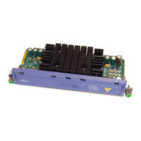
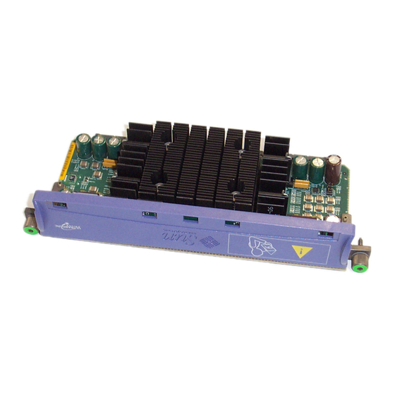
Sun Microsystems Sun Blade 1000 Cpu Module Installation Instructions (36 pages)
UltraSPARC III CPU Module
Brand:
Sun Microsystems
| Category:
Desktop
| Size: 2.81 MB
Table of Contents
Table of Contents
7
Sun Blade 1000 Ultrasparc III Module Installation Instructions
9
Firmware and Software Requirements for the Ultrasparc III 600, 750, or 900 Mhz
9
Ultrasparc III Module Installation Kit Contents
9
Firmware and Software Requirements for the Ultrasparc III 600, 750, or 900 Mhz CPU Modules
10
Ultrasparc III 600 Mhz CPU Modules
10
Ultrasparc III 750 Mhz CPU Modules
11
Ultrasparc III 900 Mhz CPU Modules
12
Sun Blade 1000 Ultrasparc III Module Installation Instructions
14
Preparing for Installation
14
Powering off the Workstation
14
Removing the Access Panel
17
Attaching the Disposable Antistatic Wrist Strap
19
About Ultrasparc III CPU Modules
20
Configuration Rules
20
CPU Module Positions in the Workstation
22
Removing a CPU Module
23
Installing a New CPU Module
28
Finishing the Installation
35
For more Information
36
Sun Microsystems Sun Blade 1000 Module Installation Manual (36 pages)
UltraSPARC III Cu Module Installation Guide
Brand:
Sun Microsystems
| Category:
Desktop
| Size: 2.81 MB
Table of Contents
Table of Contents
3
Regulatory Compliance Statements
5
Sun Blade 1000 and Sun Blade 2000 Ultrasparc III Cu CPU Module Installation Guide
9
Ultrasparc III Cu CPU Module Installation Kit Contents
9
Firmware and Software Requirements for Installing an Ultrasparc III Cu CPU Module
10
Sun Blade 1000 and Sun Blade 2000 Ultrasparc III Cu CPU Module Installation
11
Sun Blade 1000 and Sun Blade 2000 Ultrasparc III Cu CPU Module Installation Guide
12
Preparing for Installation
12
Powering off the Workstation
12
Removing the Access Panel
16
Attaching the Disposable Antistatic Wrist Strap
18
About Ultrasparc III CPU Modules
19
CPU Module Positions in the Workstation
21
Removing a CPU Module
22
Installing a New CPU Module
27
Finishing the Installation
35
For more Information
36
Advertisement
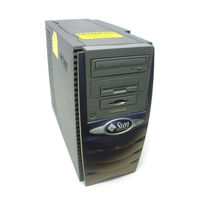
Sun Microsystems Sun Blade 1000 Manual (22 pages)
Brand:
Sun Microsystems
| Category:
Desktop
| Size: 0.22 MB
Table of Contents
Software Changes
3
Hardware Changes
13
Documentation Changes
18
Declaration of Conformity
19
Advertisement
Related Products
Sun Microsystems Sun Blade 2500
Sun Microsystems Sun Blade 100
Sun Microsystems Sun Blade 1500
Sun Microsystems Sun Blade 2000
Sun Microsystems Sun Ultra 27
Sun Microsystems Sun-1
Sun Microsystems Sun-3/260
Sun Microsystems Sun Ultra 60
Sun Microsystems Sun-3/60
Sun Microsystems Sun Ultra 450
Sun Microsystems Categories
Server
Storage
Desktop
Computer Hardware
Adapter
More Sun Microsystems Manuals
Login
Sign In
OR
Sign in with Facebook
Sign in with Google
Upload manual
Upload from disk
Upload from URL