Sign In
Upload
Manuals
Brands
RuggedCom Manuals
Network Hardware
RUGGEDBACKBONE RX1510
RuggedCom RUGGEDBACKBONE RX1510 Manuals
Manuals and User Guides for RuggedCom RUGGEDBACKBONE RX1510. We have
2
RuggedCom RUGGEDBACKBONE RX1510 manuals available for free PDF download: Installation Manual, Hardware Installation Manual
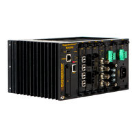
RuggedCom RUGGEDBACKBONE RX1510 Hardware Installation Manual (45 pages)
Brand:
RuggedCom
| Category:
Network Router
| Size: 5.72 MB
Table of Contents
Table of Contents
3
FCC Statement and Cautions
8
1 Product Overview
9
Functional Overview
9
Feature Highlights
9
2 Ruggedbackbone™ Modules
11
RX1510 Chassis Slot Assignment
11
Front Panel
12
Module Status Leds
12
Front View - RX1510
12
Module Status LED Indications
12
Line Modules (LM)
13
Ethernet - Copper
13
Ethernet - Fiber
13
Cg01: 2 × 10/100/1000Tx Rj45
13
Tx01: 6 × 10/100/1000Tx Rj45
13
Fx**/Fg**: 2 × 100Fx/1000Sx/1000Lx Lc
13
4Fx**: 4 × 100Fc Lc
13
Fx03: 2 × 100 Fx Mtrj
13
Fx03: 4 × 100Fx Mtrj
13
Fx**: 2 × 100Fx Sc
13
SFP Modular
14
Wan
14
Serial
14
Cellular Modem
14
Fg5*: 2 × 1000Lx/1000Sx Sfp
14
Tc1: 1 × T1/E1 Rj45
14
Fx5*: 4 × 100Fx/100Lx/100Sx Sfp
14
E01: 1 × E1 Bnc
14
Fx50: 6 × 100Fx Sfp
14
Tc2: 2 × T1/E1 Rj45
14
DDS - Digital Data Services
15
APE - Appplication Processing Engine
15
D02: 1 × Dds Rj45
15
Ape 1402
15
Power Supply
16
Screw Terminal Block Power Module: Terminal Cover in Place (HI Module Shown)
16
Screw Terminal Block Power Module: Terminal Cover Removed (HI Module Shown)
16
Pluggable Terminal Block Power Module (HIP Module Shown)
16
3 Installation
17
Mounting
17
DIN Rail Mounting: Front View
17
Rx1510Dimensions
18
DIN Rail Mounting: Side View
18
RX1510 Dimensions - Front View
18
Rx1510Dimensions - Top View
19
RX1510 Dimensions - Side View
19
Power Supply Wiring and Grounding
20
Connectors for HI and HIP Power Modules
20
Connectors for 24, 24P, 48, and 48P Power Modules
20
Screw Terminal Power Connector for HI Power Module
20
Pluggable Phoenix Power Connector for HIP Power Module
20
Screw Terminal Power Connector for 24 and 48 Power Modules
20
Pluggable Phoenix Power Connector for 24P and 48P Power Modules
20
Chassis Ground Connection
21
AC Power Supply Wiring
21
Wiring for Single AC Power Supply (HIP Module Shown)
21
DC Power Supply Wiring Examples
22
AC and DC Power Supply Wiring Example
22
Wiring for Two DC Power Supplies (24P or 48P Modules Shown)
22
Wiring for AC and DC Power Supplies (HIP Module Shown at Left; 24P or 48P Module Shown at Right)
22
Critical Alarm Wiring
23
Critical Alarm Relay Connector
23
Serial Console Port
24
WAN Ports: RJ45
24
RJ45 Serial Console Port
24
RJ45 T1/E1 Pin Configuration
24
RJ45 Serial Console Pinout
24
RJ45 T1/E1 Pin Assignment
24
WAN Ports: BNC
25
Copper Ethernet Ports
25
RJ45 Twisted-Pair Copper Ports
25
Gigabit Ethernet 1000Base-TX Cabling Recommendations
25
RJ45 Ethernet Pin Assignment
25
Transient Suppression
26
Cabling Categories and 1000Base-TX Compliance
26
Serial Ports: RJ45
27
DDS Ports: RJ45
27
RJ45 Serial Pin Configuration
27
RJ45 DDS Pin Configuration
27
RJ45 DDS Pin Assignment
27
DDS Rx and Tx LED Indications
28
SFP Optics - Installation, Removal, and Precautions
28
DDS Module Rx and Tx LED Indicators
28
DDS Rx LED Indications
28
DDS Tx LED Indications
28
Module Insertion - SFP
29
SFP Module Removal
29
SFP Module Orientation
29
SFP Module Insertion
29
Fiber Ethernet Ports
30
SFP Module Removal
30
Mtrj
30
Available Fiber Connector Types
30
Cellular Modems
31
Single Port Cellular Modem: Antenna Connections
31
Dual Port Cellular Modem: Antenna Connections
31
Cellular Modem Modules
31
GSM, EDGE, HSPA+ Cellular Modem Card
32
Installing SIM Cards for GSM, EDGE, HSPA+ Cellular Modems
32
Cellular Modem Module Assembly: W11 and W32 Single Antenna Modules
32
Cellular Modem Module Assembly: W12 Dual Antenna Modules
32
HSPA Antenna Requirements
32
APE: Application Processing Engine
34
APE Overview
34
Supported Operating Systems
34
APE Faceplate and Ports
34
APE Specifications
34
Secondary Network Interface
35
APE Chassis Network Connection
35
Installing an Operating System
36
The APE BIOS
37
Resetting the Module
37
LED Indicators
37
APE Module LED Indicators
37
Faqs
38
4 Technical Specifications
39
Power Supply Specifications
39
Critical Alarm Relay Specifications
39
Copper Ethernet Port Specifications
39
Form C Contact Relay Specifications
39
Fiber Ethernet Port Specifications
40
Fast Ethernet (100Mbps) Optical Specifications
40
SFP Fast Ethernet Transceivers
40
Gigabit Ethernet (1Gbps) Optical Specifications
41
Operating Environment
41
Mechanical Specifications
41
Fixed Gigabit Transceivers
41
SFP Gigabit Transceivers
41
5 EMI and Environmental Type Tests
42
IEC 61850-3 EMI Type Tests
42
IEEE 1613 (C37.90.X) EMI Immunity Type Tests
43
Environmental Type Tests
43
6 Agency Approvals
44
7 Warranty
45
Advertisement
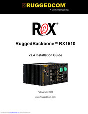
RuggedCom RUGGEDBACKBONE RX1510 Installation Manual (52 pages)
Integrated Router and Switch
Brand:
RuggedCom
| Category:
Network Hardware
| Size: 2.74 MB
Table of Contents
Table of Contents
3
FCC Statement and Cautions
5
Federal Communications Commission Radio Frequency Interference Statement
5
Chapter 1 Product Overview
7
Functional Overview
7
Feature Highlights
7
Installation
9
Chapter 2 Ruggedbackbone™ Modules
11
Installing a Module
11
Front Panel
12
Module Status Leds
13
Line Modules (LM)
13
Ethernet - Copper
13
Ethernet - Fiber
14
SFP Modular
15
Wan
15
Serial
16
Cellular Modem
16
DDS - Digital Data Services
16
Ruggedape™ (Appplication Processing Engine)
17
Power Supply
17
Chapter 3 Installation
19
Mounting
19
Rx1510Dimensions
21
Power Supply Wiring and Grounding
23
Connectors for HI and HIP Power Modules
23
Connectors for 24, 24P, 48, and 48P Power Modules
24
Chassis Ground Connection
24
AC Power Supply Wiring
25
DC Power Supply Wiring Examples
25
AC and DC Power Supply Wiring Example
26
Critical Alarm Wiring
26
Serial Console Port
27
WAN Ports: RJ45
28
WAN Ports: BNC
28
Copper Ethernet Ports
28
RJ45 Twisted-Pair Copper Ports
29
M12 Twisted Pair Copper Ports
29
Gigabit Ethernet 1000Base-TX Cabling Recommendations
30
Transient Suppression
31
Serial Ports: RJ45
31
DDS Ports: RJ45
32
DDS Rx and Tx LED Indications
32
SFP Optics - Installation, Removal, and Precautions
33
Module Insertion - SFP
33
SFP Module Removal
34
Fiber Ethernet Ports
35
Cellular Modems
36
GSM, EDGE, HSPA+ Cellular Modem Card
37
Installing SIM Cards for GSM, EDGE, HSPA+ Cellular Modems
38
Chapter 4 Technical Specifications
39
Power Supply Specifications
39
Critical Alarm Relay Specifications
39
Copper Ethernet Port Specifications
40
Fiber Ethernet Port Specifications
40
Fast Ethernet (100Mbps) Optical Specifications
40
Gigabit Ethernet (1Gbps) Optical Specifications
41
Operating Environment
42
Ruggedape™ Specifications
42
Mechanical Specifications
43
Chapter 5
45
EMI and Environmental Type Tests
45
Chapter 6
49
Agency Approvals
49
Chapter 7
51
Warranty
51
Advertisement
Related Products
RuggedCom RuggedVDSL RS910L
RuggedCom RuggedBackbone RX1512
RuggedCom RUGGEDBACKBONE RX1501
RuggedCom RuggedRouter RX1100
RuggedCom RuggedRouter RX1000
RuggedCom RuggedBackbone RX1500
RuggedCom RUGGEDBACKBONE RX5000
RuggedCom RMC-100-MM
RuggedCom RMC-10-MM
RuggedCom RuggedSwitch RS950G
RuggedCom Categories
Switch
Network Router
Server
Network Hardware
Media Converter
More RuggedCom Manuals
Login
Sign In
OR
Sign in with Facebook
Sign in with Google
Upload manual
Upload from disk
Upload from URL