Sign In
Upload
Manuals
Brands
Ricoh Manuals
Printer
SP 8400DN
Ricoh SP 8400DN Manuals
Manuals and User Guides for Ricoh SP 8400DN. We have
4
Ricoh SP 8400DN manuals available for free PDF download: Field Service Manual, User Manual, Manual, Quick Installation Manual
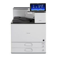
Ricoh SP 8400DN Field Service Manual (2221 pages)
Ricoh A3 size black and white laser printer.
Brand:
Ricoh
| Category:
Printer
| Size: 63.61 MB
Table of Contents
Table of Contents
16
Product Information
28
Product Overview
28
Component Layout
28
Paper Path
29
Drive Layout
31
Machine Codes and Peripherals Configuration
32
System Configuration and Options
32
Specifications
34
Installation
35
Installation Requirements
35
Environment
35
Machine Space Requirements
36
Machine Dimensions
36
Power Requirements
39
Who Installs the Peripherals and Options
40
Main Machine Installation
41
Installation Flow Chart
41
Accessory Check
42
Installation Procedure
43
Check Image Quality / Settings
49
Security Settings
52
Auto Remote Firmware Update (ARFU) Settings
67
Moving the Machine
73
Paper Feed Unit PB3240 (M494-17, -21)
76
Accessory Check
76
Installation Procedure
76
Lcit Pb3260 (M496-17, -27)
82
Accessory Check
82
Installation Procedure
82
Lcit Rt3030 (D696-17, -27)
89
Accessory Check
89
Installation Procedure
89
Anti-Condensation Heater
97
Overview
97
Heater Board
99
PCU Heater
105
Tray Heater for Main Unit
112
Tray Heater for Paper Feed Unit PB3240
113
Tray Heater for LCIT PB3260
116
Bridge Unit BU3070 (D685-18)
119
Accessory Check
119
Installation Procedure
119
Internal Multi-Fold Unit FD3000 (M482-17)
125
Accessory Check
125
Installation Procedure
126
When Attaching a Finisher Downstream from the Internal Multi-Fold Unit
142
Finisher SR3230 (D3BA-17, -21)
144
Accessory Check
144
Installation Procedure
145
Attaching a Support Tray
151
Output Jogger Unit Type M25 (D3CJ-01)
154
Accessory Check
154
Installation Procedure
154
Punch Unit PU3060 (D706-00, -01, -02)
165
Accessory Check
165
Installation Procedure
166
Product Overview
196
Paper Path
196
Drive Layout
198
Specifications
201
Installation
202
Installation Requirements
202
Environment
202
Machine Dimensions
203
Power Requirements
206
Accessory Check
209
Installation Procedure
210
Security Settings
219
Installation Procedure
228
Accessory Check
243
Accessory Check
265
Heater Board
265
PCU Heater
271
Finisher SR3210 (D3B8-17, -21)
310
Accessory Check
311
Installation Procedure
312
Attaching a Proof Support Tray
352
Stapleless Stapler Initial Settings
354
Installation Procedure
356
Accessory Check
366
Component Check
390
Installation Procedure
390
Indicator Behavior
401
NFC Card Reader Type P11 (M512-18)
402
Accessory Check
402
Installation Procedure
403
External NFC Card Reader Bracket Type P11 (M512-17)
412
Accessory Check
412
Installation Procedure
413
Internal Options
423
IEEE 1284 Interface Board Type M19 (D3C0-17)
424
Accessory Check
424
Installation Procedure
424
IEEE 802.11A/B/G/N Interface Unit Type M19 (D3BR-01)
426
Accessory Check
426
Installation Procedure
426
User Tool Settings for IEEE 802.11A/B/G/N
428
SP Mode Settings for IEEE 802.11 Wireless LAN
429
HDD Option Type P13 (M513-19)
431
Component Check
431
Installation Procedure
431
Extended USB Board Type M19 (D3BS-01)
435
Component Check
435
Installation Procedure
435
SD Card Options
437
SD Card Slots
437
List of Slots Used
437
SD Card Appli Move
438
Overview
438
Move Exec
439
Undo Exec
441
Postscript3 Unit Type P13 (M513-22, -23, -24)
443
Accessory Check
443
Overview of Postscript3 Unit Type P13 (Adobe PS)
443
Installation Procedure (Adobe PS)
443
XPS Direct Print Option Type P13 (M513-09, -10, -11)
447
Accessory Check
447
Installation Procedure
447
VM Card Type P13 (M513-25, -26, -27)
449
Accessory Check
449
Installation Procedure
449
IPDS Unit Type P13 (M513-13, -14, -15)
451
Accessory Check
451
Installation Procedure
451
Remote Settings
453
Operation Guidance for Users
458
Preventive Maintenance
459
PM Parts Settings
459
Replacement Procedure of the PM Parts
459
After Installing the New PM Parts
461
PM Parts List
463
Replacement and Adjustment
464
Notes on the Main Power Switch
464
Push Switch
464
Beforehand
467
Special Tools and Lubricants
468
Exterior Covers
469
Overview
469
Quick Reference for Removing Covers
471
Front Cover
471
Controller Cover
472
Left Upper Cover
474
Left Rear Cover
474
Left Cover
474
Rear Left Cover
476
Rear Cover
476
Rear Lower Gap Cover
477
Rear Lower Cover
477
Right Rear Cover
477
Right Upper Cover
478
Right Cover
479
Upper Front Cover
480
Main Power Switch Cover
481
Paper Exit Tray
482
Paper Exit Cover
482
Paper Exit Lower Cover
483
Upper Inner Cover
483
Paper Exit Front Cover
485
Top Right Cover
485
Inner Cover
486
Toner Supply Housing
488
Smart Operation Panel
490
Operation Panel Unit
490
Internal Parts
493
USB Cable / Harness
493
Laser Unit
496
Caution Decal Location
496
Quenching Lamp
499
PCL (Pre Cleaning Light)
500
Pcdu
501
Pcu/Development Unit
503
OPC Drum
505
Charge Roller, Cleaning Roller
508
Pick-Off Pawls
508
Cleaning Blade
508
Developer
509
Development Filters
514
TD Sensor
515
Development Mixing Auger Bearings
515
Development Mixing Auger (L / R)
517
Waste Toner
519
Waste Toner Bottle
848
Toner Collection Full Sensor
1074
Recycling Shutter
1075
Transfer Unit
1078
Transfer Roller Unit
1079
ID Sensor
1080
Transfer Unit Open/Closed LED
1081
Temperature/Humidity Sensor
1082
Fusing Entrance Sensor
1083
Transfer Unit Open/Closed Sensor
1083
Drive Unit
1085
Drum/Waste Toner Motor
1085
Development Motor
1085
Fusing Motor
1085
Paper Exit Motor
1086
Registration Motor
1086
Paper Feed Motor
1087
Vertical Transport Motor
1087
Transfer Roller Contact Motor
1087
Toner Hopper
1088
Specifications
1464
General Specifications
1464
Mainframe
1464
Printer Specifications
1469
Supported Paper Sizes
1471
Paper Feed
1471
Paper Exit
1475
Software Accessories
1484
Printer Drivers
1484
Optional Equipment
1485
Finisher SR3210 (D3B8)
1485
Finisher SR3230 (D3BA)
1486
Mail Box CS3010 (M481)
1490
Bridge Unit BU3070 (D685)
1490
Output Jogger Unit Type M25 (D3CJ)
1491
Punch Unit PU3050 NA/EU/SC (D717)
1491
Punch Unit PU3060 NA/EU/SC (D706)
1492
Internal Multi-Fold Unit FD3000 (M482)
1493
Paper Feed Unit PB3240 (M494)
1493
Lcit Pb 3260 (M496)
1494
Lcit Rt 3030 (D696)
1494
Preventive Maintenance
1495
Preventive Maintenance Items
1495
Optional Peripheral Devices
1499
Other Yield Parts
1503
Engine SP Mode Tables
1504
Engine SP1-XXX (Feed)
1504
Engine SP2-XXX (Drum)
1521
Engine SP3-XXX (Process)
1525
Engine SP4-XXX (Locpp Edge Level)
1533
Engine SP5-XXX (Mode)
1534
Engine SP6-XXX (Peripherals)
1540
Engine SP7-XXX (Data Log)
1597
Input Check Table
1608
Main Machine, Paper Feed Tray
1608
Finisher / Mail Box / Folding Unit
1614
Replacement and Adjustment
1747
Operation Panel Unit
1748
Micro Computer Board
1752
Wi-Fi Module
1752
Lcd
1752
Speaker
1754
Microphone
1755
Mechanism
1758
Overview
1758
System Components
1758
Panel Components/Screen Layout
1768
Electrical Components
1771
Controlling the Power Supply
1773
Exiting Energy Saving Modes
1773
Screen Startup Mode
1773
Shutdown Functions
1774
System Maintenance
1777
Maintenance Modes
1777
Service Mode Menu
1779
Panel Self Check
1782
Recovery Mode
1789
Special Key Combinations
1789
Software Update
1791
Updating the Smart Operation Panel
1791
Installation/Update from an SD Card
1791
Package Update
1792
Installation/Update from the Edc Server
1796
Application Site
1798
Troubleshooting
1799
Software Update Errors
1799
Errors that Occur When the Control Panel Downloads Data from the Controller at Startup
1804
Detailed Description
1810
Mechanism Descriptions
1810
Component Layout
1810
Mechanism Details
1811
Replacement and Adjustment
1812
Jogger Unit Removal
1816
Sensors
1816
Front Fence Sensor, Rear Fence Sensor
1816
Lift Sensors
1817
Motors
1823
Front Fence Motor
1823
Rear Fence Motor
1825
Fence Lift Motor
1827
Board
1832
Main Board
1832
Front Cover
1845
Inner Cover
1845
Rear Cover
1847
Front Left Cover
1848
Upper Cover
1848
Upper Rear Cover
1850
Paper Exit Guide Cover
1850
Upper Left Cover
1850
Proof Tray
1853
Shift Tray
1854
Booklet Tray (SR3220)
1854
Left Center Cover
1854
Left Lower Cover
1855
Main Unit
1857
Paper Exit Guide Plate Open/Close Motor
1857
Paper Exit Guide Plate Open/Close HP Sensor
1857
Proof Tray Full Sensor
1858
Proof Tray Paper Exit Sensor
1858
Entrance Sensor
1860
Intermediate Transport Sensor Right
1860
Intermediate Transport Sensor Left
1860
Shift Tray Paper Surface Sensor
1861
Shift Tray Upper Limit Switch
1862
Shift Tray Paper Exit Sensor
1863
Paper Exit Guide HP Sensor
1863
Entrance Transport Motor
1928
Proof Transport Motor
1929
Drive Motor Unit
1965
Paper Exit Sensor
1968
Relay Transport Sensor
1972
Paper Exit Tray Set Switch
1973
Relay Transport Unit Set Switch
1974
Detailed Descriptions
1977
Bridge Unit BU3070 (D685)
1977
Parts Layout
1977
Mechanism
1978
Drive Mechanism
1978
Paper Transport Mechanism
1979
Rear Cover
1989
Front Cover
1992
Upper Cover
1993
Right Cover
1994
Pick-Up Roller, Feed Roller, Friction Roller
1995
Paper Feed Motor
1998
Transport Motor
1999
Tray Lift Unit
2000
Controller Board
2001
Tray Set Switch (Front)
2002
Tray Set Switch (Rear)
2003
Paper Feed Sensor, Paper End Sensor, Upper Limit Sensor, Transport Sensor
2004
Detailed Descriptions
2009
Lcit Rt3030 (D696)
2009
Changes from the Previous Machine
2009
Parts Layout
2010
Mechanism
2012
Paper Feed Separating Mechanism
2012
Replacement and Adjustment
2024
Rear Cover
2025
Left and Right Trays
2026
Left Tray Paper Sensor
2027
Paper Transfer Home Position Sensor
2028
Controller Board
2029
Paper Feed Unit
2030
Lower Limit Sensor
2032
Left Tray Set Sensor Switch
2033
Right Tray Set Sensor Switch
2034
Tray Lift/Paper Transfer Unit
2035
Tray Lift Motor
2036
Paper Transfer Motor
2037
Remaining Paper Sensor
2038
Paper Feed Motor
2039
Paper Transport Motor
2040
Pick-Up Roller, Feed Roller, Friction Roller
2041
Paper Transport Sensor, Paper Feed Sensor, Paper End Sensor, Upper Limit Sensor
2043
Right Tray Side Fence
2046
Detailed Descriptions
2047
Parts Layout
2047
Mechanism
2049
Paper Feed Separation Mechanism
2049
Drive Mechanism
2049
Friction Roller/Pick-Up Roller Release Mechanism
2049
Paper Feed Transport Mechanism
2049
Tray Lift/Descent Mechanism
2050
Left Tray Transfer Fence Mechanism
2051
Remaining Paper Detection
2052
Replacement and Adjustment
2061
Covers
2061
Front Cover, Front Left Side Cover
2062
Paper Guide Cover
2064
Proof Tray
2066
Shift Tray
2067
Left Cover
2067
Boards
2069
Main Board
2069
Paper Guide
2071
Paper Guide Unit
2071
Main Motors
2074
Corner Stapling Unit
2074
Paper Exit Gate Motor
2079
Leading Edge Guide Motor
2079
Trailing Edge Pressure Plate Motor
2080
Stacking Roller Motor
2080
Feed out Motor
2081
Jogger Motor
2081
Paper Guide Motor
2082
Sensors
2084
Shift Tray Paper Sensor
2084
Trailing Edge Pressure Plate HP Sensor
2084
Stacking Roller HP Sensor
2085
Staple Tray Paper Sensor
2087
Paper Guide HP Sensor
2088
Stapler Unit
2090
Punch Unit
2093
Detailed Descriptions
2096
Layout
2096
General Layout
2096
Electrical Component Layout
2097
Transport Layout
2100
Proof Transport Layout (Drive)
2101
Proof Transport Layout (Sensors)
2101
Shift Transport Layout (Drive)
2102
Replacement and Adjustment
2122
Exterior Covers
2126
Rear Cover
2126
Top Cover
2127
Front Cover
2127
Paper Exit Covers 1-4
2129
Motors
2130
Paper Transport Motor
2130
Paper Exit Motor
2130
Solenoids
2133
Junction Gate Solenoids 1-3
2133
Inverter Solenoid
2133
Sensors
2135
Door Sensor
2135
Inverter Guide Door Sensor
2135
Paper Exit Tray Full Sensors 1-3
2136
Paper Exit Tray Full Sensor 4
2136
Paper Transport Sensors 1, 2
2137
Paper Entrance Sensor
2138
Controller Board
2140
Paper Exit Driven Rollers 1-4
2141
Installing the Paper Exit Driven Roller
2141
Detailed Descriptions
2145
Parts Layout
2145
Paper Path
2146
Mechanism
2147
Drive and Inverter Mechanism
2147
Paper Separation and Transport Mechanism
2148
Tray Full Detection
2149
Replacement and Adjustment
2158
Removing the Internal Multi-Fold Unit
2159
Exterior Covers
2162
Rear Cover
2162
Door
2162
Front Right Cover
2163
Front Left Cover
2164
Top Cover
2165
Exit Unit Cover
2165
Motors, Solenoid
2167
JG Crease Motor
2167
Transport Motor
2167
Registration Motor
2167
2Nd Fold Motor
2168
1St Fold Motor
2168
Junction Gate Solenoid
2169
Switches
2170
Exit Unit Switch
2170
Front Door Switch
2170
Sensors
2171
Crease HP Sensor
2171
Junction Gate HP Sensor
2171
Registration Sensor
2172
Crease Sensor
2173
1St Fold Sensor
2175
2Nd Fold Sensor
2176
Folder Tray Exit Sensor
2177
Folder Tray Full Sensor
2177
Folder Tray Full Sensor 2
2178
Horizontal Path Exit Sensor
2179
Pcb
2182
Detailed Descriptions
2183
Sensor Layout
2183
Roller Layout
2184
Drive Layout
2185
Parts Layout
2186
Replacement and Adjustment
2201
Rear Cover
2201
Motors
2202
Tray Lift Motor (Upper)
2202
Tray Lift Motor (Lower)
2202
Transport Motor
2202
Paper Feed Motor
2203
Board
2204
Controller Board
2204
Sensors
2205
Transport Sensor
2205
Paper Feed Sensor
2205
Paper End Sensor
2206
Upper Limit Sensor
2207
Paper Feed Unit
2208
2Nd Paper Feed Unit
2208
1St Paper Feed Unit
2211
Rollers
2213
Pick-Up Roller
2213
Feed Roller
2213
Friction Roller
2214
Detailed Descriptions
2215
Parts Layout
2215
Mechanism
2217
Paper Feed Separation Mechanism
2217
Drive Mechanism
2217
Friction Roller/ Pick-Up Roller Release Mechanism
2217
Paper Feed Transport Mechanism
2217
Tray Base Plate Lift
2218
Paper Size Detection
2219
Remaining Paper Detection/Paper End Detection
2220
Advertisement
Ricoh SP 8400DN User Manual (108 pages)
Black and White
Brand:
Ricoh
| Category:
Printer
| Size: 4.48 MB
Table of Contents
User Guide
1
Table of Contents
3
Manuals for this Machine
6
1 Getting Started
9
Before You Start
9
How to Read the Manuals
9
Model-Specific Information
10
List of Options
11
Guide to Names and Functions of Components
13
Guide to Functions of the Attention Light
15
Guide to Functions of the Machine's Options
18
Guide to Functions of the Machine's External Options
18
Guide to Functions of the Machine's Internal Options
19
Guide to the Names and Functions of the Machine's Control Panel
21
Changing the Display Language
22
How to Use the [Home] Screen
23
Main Icons on the [Home] Screen
25
[Printer (Classic)] Screen
26
[Information] Screen
27
Possible Operations on the Screen
28
Adding Icons to the [Home] Screen
30
Turning On/Off the Power
32
Saving Energy
33
Accessing User Tools
35
Changing Default Settings
35
Quitting User Tools
36
Using Web Image Monitor
37
Displaying Top Page
38
Replenishing and Replacing Consumables
40
Adding Toner
40
Adding Staples
42
Replacing Other Consumables
42
2 Loading Paper
45
Precautions for Loading Paper
45
Loading Paper into Paper Trays
45
Loading Paper into the Bypass Tray
47
Loading Paper into Tray 3 (LCT)
48
Loading Paper into the Large Capacity Tray (LCT)
50
Loading Orientation-Fixed Paper or Two-Sided Paper
51
Recommended Paper
53
Recommended Paper Sizes and Types
53
Thick Paper
59
Printing from the Bypass Tray
63
Specifying Regular Sizes Using the Control Panel
63
Specifying a Custom Size Paper Using the Control Panel
63
Specifying Thick Paper, Thin Paper, or OHP Transparencies for Paper Type Using the Control Panel
64
3 Troubleshooting
67
When the Machine Makes a Beeping Sound
67
When a Status Icon Is Displayed
68
When the Indicator Lamp for [Check Status] Is Lit or Flashing
69
When You Have Problems Operating the Machine
71
If USB Connection Fails
75
Messages Displayed When You Use the Printer Function
76
Messages Displayed on the Control Panel When You Use the Printer Function
76
Messages Printed on the Error Logs or Reports When You Use the Printer Function
79
When Other Messages Appear
81
When Problems Occur While Logging in
82
When the User Lacks Privileges to Perform an Operation
82
When You Cannot Print
83
Other Printing Problems
85
Removing Jammed Paper
94
Locating Jammed Paper
94
4 Information for this Printer
97
Information on Environmental Regulations
97
ENERGY STAR Program
97
Energy Saving Functions
97
User Information on Electrical and Electronic Equipment (Mainly Europe)
99
Environmental Advice for Users (Mainly Europe)
100
Trademarks
102
Index
105
Ricoh SP 8400DN Manual (73 pages)
Brand:
Ricoh
| Category:
Printer
| Size: 4.12 MB
Table of Contents
Manuals for this Machine
3
Safety Information for this Machine
5
Safety Information
6
Safety Labels of this Machine
13
Positions of RWARNING and RCAUTION Labels
13
Main Unit
13
Paper Trays
14
Symbols for Power Switch
16
Other Information for this Machine
17
Legal Prohibition
17
Laser Safety
17
Información de Seguridad de Esta Máquina
23
Información de Seguridad
24
Etiquetas de Seguridad de Esta Máquina
31
Unidad Principal
31
Bandejas de Papel
32
Más Información sobre Esta Máquina
35
Leia Isto Primeiro
37
Português (Brasil)
37
Informações de Segurança
42
Etiquetas de Segurança Neste Equipamento
49
Unidade Principal
49
Outras Informações Relativas a Este Equipamento
53
À Lire Avant de Commencer
55
Informations Générales
57
Manuels Pour Cet Appareil
57
Consignes de Sécurité Pour Cet Appareil
59
Consignes de Sécurité
60
Étiquettes de Sécurité de Cet Appareil
67
Appareil de Base
67
Autres Informations Sur Cet Appareil
71
Advertisement
Ricoh SP 8400DN Quick Installation Manual (2 pages)
Brand:
Ricoh
| Category:
Printer
| Size: 1.4 MB
Advertisement
Related Products
Ricoh Aficio SP 8100DN
Ricoh Aficio SP 8300DN
Ricoh SP 8200DN
Ricoh Aficio SP C320DN
Ricoh Aficio SP 3510DN
Ricoh Aficio SP C830DN
Ricoh Aficio SP C831DN
Ricoh Aficio SP C820DN
Ricoh Aficio SP 3300DN
Ricoh SP 203 SF
Ricoh Categories
All in One Printer
Printer
Digital Camera
Copier
Printer Accessories
More Ricoh Manuals
Login
Sign In
OR
Sign in with Facebook
Sign in with Google
Upload manual
Upload from disk
Upload from URL