Sign In
Upload
Manuals
Brands
Ricoh Manuals
All in One Printer
Aficio MP 3350SP
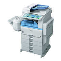
Ricoh Aficio MP 3350SP Manuals
Manuals and User Guides for Ricoh Aficio MP 3350SP. We have
2
Ricoh Aficio MP 3350SP manuals available for free PDF download: Service Manual, Installation Manual
Ricoh Aficio MP 3350SP Service Manual (1153 pages)
D017/D018/D019/D020
Brand:
Ricoh
| Category:
Printer
| Size: 30.01 MB
Table of Contents
D017/D018/D019/D020
13
Table of Contents
13
D361 Fax Option Type
31
Installation
35
Power Requirements
36
System Configuration and Options
37
Copier Installation
40
Installation Flow Chart
41
Accessory Check
42
Developer
43
Re-Assembly
45
Toner Bottle
46
Emblem, Decals
47
SP Settings
48
Transporting the Machine
49
Paper Tray Unit (D331)
50
SP Settings
52
Lct (B391)
53
SP Setting
56
Ardf (D366)
57
Interchange Unit (D371)
61
Bin Tray Unit (D367)
63
Shift Tray (D385)
67
Bypass Feed Unit (D370)
70
Duplex Unit (D369)
73
Bridge Unit (D368)
77
Installation Procedure
78
Sheet Finisher (B408)
79
Installation Procedure
80
Sheet Booklet Finisher (B793)
82
Installation Procedure
83
Sheet Finisher (D372)
87
Platen Cover (B406)
90
Key Counter (B452)
91
Heaters
93
Tray Heater (Copier)
94
Tray Heater (Optional Paper Tray Unit)
95
Tray Heater (Optional Lct)
99
Copy Data Security Unit (B829)
103
Hard Disk (D362, Only for D017/D019)
106
Hdd Encryption Unit
107
Recovery from a Device Problem
109
Clearing the NVRAM
110
Procedure Flow
111
Encryption Key Restoration
112
Data Overwrite Security Unit (D362)
113
Seal Check and Removal
114
Browser Unit Type D (D377)
117
File Format Converter Type E (D377)
118
VM Card Type E (D377)
119
Preventive Maintenance
123
Main Motor Drive Gear
129
Replacement and Adjustment
133
General Cautions
134
Laser Unit
135
Scanner Unit
136
Exposure Lamp
137
Reassembling
139
Scanner Motor
140
Color Scanner Unit
141
When Reassembling
142
Front Scanner Wire
143
Rear Scanner Wire
146
Touch Panel Position Adjustment
147
Laser Unit
148
Polygon Mirror Motor
151
Laser Synchronization Detector
152
Photoconductor Unit (Pcu)
153
Pick-Off Pawls
154
Charge Roller, Cleaning Roller
155
Cleaning Blade
156
After Replacement of Pcu Components
161
Transfer Unit
163
Image Density Sensor
164
Fusing/Exit
165
Thermistors
166
Hot Roller and Fusing Lamps
168
Pressure Roller/Cleaning Roller
170
Paper Exit Sensor/Paper Overflow Sensor
171
Paper Feed
172
Feed Roller: Tray 2
173
Paper End Sensor
174
Registration Clutch
175
Paper Feed Clutches
176
Relay Clutches
177
Upper/Lower Paper Size Sensors
178
Upper, Lower Relay Sensors
181
Dust Collection bin
182
Pcbs and Other Items
183
After Installing the Controller Board
185
Bcu Board
186
Power Pack
187
Monochrome Scanner Unit (D017/D019)
189
Copy Adjustments: Printing/Scanning
193
Blank Margin
194
Main Scan Magnification
195
Parallelogram Image Adjustment
196
Scanning
197
Adf Image Adjustment
198
Sub Scan Magnification
199
Troubleshooting
203
Sc Code Descriptions
204
Self-Diagnostic Mode
237
Self-Diagnostic Test Flow Chart
238
Detailed Self-Diagnostic Mode
239
Paper Feed Troubleshooting
241
Skewed Image
242
Image Problems
243
Trapezoid Images
244
Parallelogram Images
245
Checking Images with the Trimming Pattern
246
Correcting the Images
247
Correcting Trapezoid Images
251
Correcting Parallelogram Images
252
Electrical Component Defects
253
Switches
260
Blown Fuse Conditions
261
Service Tables
265
Entering and Exiting SP Mode
266
Switching between SP Mode and Copy Mode for Test Printing
267
Commonly Used Sp Codes and Features
268
Test Pattern Printing (SP2902)
269
SMC Data Lists (SP5990)
270
Memory All Clear (SP5801)
271
APS Output Display (SP4301)
273
Nip Band Width Measurement (SP1109)
274
System Setting Reset
275
Service Program Mode Tables
276
Sp1Xxx: Feed
277
Sp2Xxx: Drum
285
Sp3Xxx
304
Sp4Xxx: Scanner
305
Sp5Xxx: Mode
334
Sp6Xxx: Peripherals
403
Sp7Xxx: Data Log
421
Sp8Xxx: Data Log 2
433
Firmware Update
477
User Tools
478
Printer, Facsimile, Scanner Settings
479
Led and Dip Switches
480
Sbcu
481
Using the Debug Log
482
Retrieving the Debug Log from the Hdd
486
New Debug Log Codes
487
Detailed Section Descriptions
491
Paper Path
493
Electrical Component Descriptions
494
Drive Layout
501
Board Structure
502
Controller Board
504
Copy Process
506
Scanning
508
Scanner Drive
509
Original Size Detection
510
Anti-Condensation Heater
511
Image Processing
512
Sbu (Sensor Board Unit)
513
Color Scanner Unit
514
Auto Image Density
515
Original Type Settings
516
Ipu (Image Processing Unit)
517
Laser Exposure
519
Auto Power Control (Apc)
520
Ld Safety Switch
521
Photoconductor Unit (Pcu)
522
Drive
523
Drum Charge
524
Charge Roller Voltage Correction
525
ID Sensor Pattern Production Timing
526
Development
527
Drive
528
Development Bias
529
Toner Supply
530
Toner Supply Mechanism
531
Toner Density Sensor Initial Setting
534
Toner Supply Determination
535
Toner Supply in Abnormal Sensor Conditions
536
Toner Near-End/End Detection and Recovery
537
Drum Cleaning and Toner Recycling
538
Toner Recycling
539
Paper Feed
540
Paper Feed Drive
541
Paper Feed and Separation
542
Paper Lift
543
Paper End Detection
544
Side and End Fences
545
Paper Registration
546
Paper Size Detection
547
By-Pass Tray
550
Paper Height Detection
552
Feed Pressure Adjustment for Paper Size
553
Special Paper Setting
555
Tray Lock Mechanism
556
Image Transfer and Paper Separation
557
Transfer Roller Cleaning
558
Paper Separation Mechanism
559
Image Fusing and Paper Exit
560
Fusing Drive and Release Mechanism
561
Pressure Roller
562
Fusing Temperature Control
563
Overheat Protection
564
Paper Exit
565
Energy Saver Modes
566
What Happens in Energy Saver Mode
567
Entering off Stand-By and off Modes
568
Specifications
571
Options
573
Duplex Unit (D369)
574
Interchange Unit (D371)
575
Bridge Unit (D368)
576
Paper Tray Unit (D331)
577
Sheet Finisher (D372)
578
Sheet Finisher (B408)
580
Sheet Finisher (B793)
581
Table of Contents
638
Proof Tray
680
Shift Tray
681
Up/Down Motion
681
Side-To-Side Motion
682
Booklet Tray
683
Jogger Unit
686
Exit Guide Plate, Paper Feed out
687
Stapler Unit Movement
688
Stacking for Booklet Stapling
689
Overview
689
14 (Legal) or Shorter
689
Longer than 8.5 X 14 Inches
690
Moving the Stack to the Folding Position
692
Folder
693
Overview
693
Fold Plate
693
Fold Rollers
694
Punch Unit
697
Paper Position Detection
697
Punch Unit Movement
698
Punch Selection and Firing
698
Punch Hopper Mechanism
699
Detailed Section Descriptions/Specifications
732
Printer Switches
815
Communication Switches
824
G3 Switches
835
G3-2 and G3-3 Switches
845
G4 Internal Switches
854
G4 Parameter Switches
854
Ip Fax Switches
855
Ncu Parameters
863
Dedicated Transmission Parameters
879
Parameters
879
Programming Procedure
879
Service Ram Addresses
889
Detailed Section Descriptions
900
Overview
900
Boards
901
Fcu
901
Mbu
902
Sg3 Board
902
Video Data Path
904
Transmission
904
Reception
906
Fax Communication Features
907
Document Server
907
Multi-Port
907
Internet Mail Communication
908
Ip-Fax
918
Packet Format
918
Settings
918
What Is Ip-Fax
918
Specifications
919
General Specifications
919
Capabilities of Programmable Items
921
Ifax Specifications
922
Ip-Fax Specifications
923
Fax Unit Configuration
924
Service Tables
928
Skew Correction
951
Original Transport and Exit
952
Conditions for Jam Detection
953
Service Tables
955
Dip Switches
955
Specifications
1034
Positioning Roller
1052
Positioning Roller Initialization
1063
Jogging (Paper Alignment)
1064
Overview
1064
Side Fence Operation
1065
Side Fence Initialization
1068
Side Fence Motor Errors
1068
Side Fence Operation Adjustment
1069
Stapling
1071
Overview
1071
Stapler Movement Motor Initialization
1073
Stapler Errors
1074
Paper Output
1075
Overview
1075
Feed-Out
1078
Feed-Out Belt Initialization
1079
Feed-Out Belt Errors
1079
Feed-Out Extension
1080
Tray Operation
1082
Overview
1082
Tray Lift Control
1083
Tray Initialization
1086
Tray Lift Errors
1087
Electrical Components
1089
Component Layout
1089
Summary of Electrical Components
1090
Timing Charts
1093
Error List
1094
Specifications
1100
Internal Shift Tray Sh3010 D385
1143
Internal Shift Tray Sh3010 D385
1145
1 Overall Machine Information
1147
Specifications
1147
Component Layout
1148
2 Detailed Section Descriptions
1149
Basic Operation
1149
Primary Mechanisms
1150
Tray Shift
1150
Half Turn Detection
1151
3 Replacement and Adjustment
1152
Tray Cover Replacement
1152
Tray Cover Attachment
1152
Tray Cover Removal
1152
Tray Motor and Half Turn Sensor Replacement
1153
Replacing the Half Turn Sensor
1153
Replacing the Tray Motor
1153
Advertisement
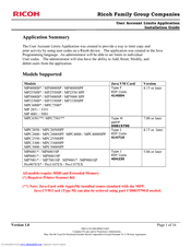
Ricoh Aficio MP 3350SP Installation Manual (16 pages)
User Account Limits Application Installation Guide
Brand:
Ricoh
| Category:
All in One Printer
| Size: 0.53 MB
Table of Contents
Installation Guide
1
Required Software
2
Installation Procedure
2
Uninstall Procedure
11
Advertisement
Related Products
Ricoh Aficio MP 3352
Ricoh MP 3353
Ricoh MP3300
Ricoh Aficio MP 3351
Ricoh MP 3353 Series
Ricoh MP 3353SP
Ricoh MP3350SPF
Ricoh Aficio MP 3352SP
Ricoh Aficio MP 3500g
Ricoh MP 3053SP
Ricoh Categories
All in One Printer
Printer
Digital Camera
Copier
Printer Accessories
More Ricoh Manuals
Login
Sign In
OR
Sign in with Facebook
Sign in with Google
Upload manual
Upload from disk
Upload from URL