Sign In
Upload
Manuals
Brands
Omron Manuals
Industrial PC
NYB17-13
Omron NYB17-13 Manuals
Manuals and User Guides for Omron NYB17-13. We have
1
Omron NYB17-13 manual available for free PDF download: User Manual
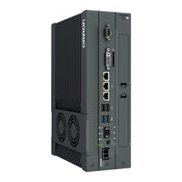
Omron NYB17-13 User Manual (244 pages)
Industrial Box PC NY-series
Brand:
Omron
| Category:
Industrial PC
| Size: 10.27 MB
Table of Contents
Introduction
3
Table of Contents
4
Intended Audience
3
Applicable Products
3
Manual Information
9
Page Structure
9
Special Information
10
Terms and Conditions Agreement
11
Warranty and Limitations of Liability
11
Application Considerations
12
Disclaimers
12
Safety Precautions
14
Definition of Precautionary Information
14
Symbols
14
Warnings
15
Cautions
17
Precautions for Safe Use
18
Disassembly, Dropping, Mounting, Installation and Storage
18
Wiring
18
Power Supply Design and Turning ON/OFF the Power Supply
18
Actual Operation
19
Operation
19
General Communications
20
Battery Replacement
20
Cleaning, Maintenance and Disposal
20
Precautions for Correct Use
21
Storage, Installation and Mounting
21
Wiring
21
Actual Operation and Operation
22
Battery Replacement
22
SD Memory Cards
22
Regulations and Standards
23
Conformance to EU Directives
23
Conformance to KC Standards
24
Conformance to UL and CSA Standards
24
Software Licenses and Copyrights
24
Related Manuals
25
Related Products Manuals
25
Industrial Monitor Manual
25
Terminology and Abbreviations
26
Industrial PC Platform
26
Hardware
26
Software
26
Revision History
28
Sections in this Manual
29
Overview
32
Intended Use
32
Hardware Features
33
ID Information Label
34
Label with Controller License (Optional)
34
Product Configuration
35
Industrial PC Platform Overview
36
Industrial Monitor
36
Industrial Box PC
37
Industrial Panel PC
37
Component Names and Functions
40
Front and Top of the Industrial Box PC
40
Back of the Industrial Box PC
42
LED Indicators
43
PWR LED Indicator
43
ERR LED Indicator
44
HDD LED Indicator
44
RUN LED Indicator
44
Power Button
45
Drive Bays
46
SD Memory Card Slot
47
Pcie Card Slot
48
Connectors
49
Power Connector
49
I/O Connector
49
USB Connectors
50
Ethernet Connectors
51
DVI Connector
51
RS-232C Connector (Optional)
52
DVI-D Connector (Optional)
52
Spare Parts
53
Battery
53
Fan Unit
53
Accessory Kit
54
Optional Hardware
55
Mounting Brackets
55
SD Memory Cards
55
USB Flash Drives
56
Storage Devices
56
DVI Cables
57
USB Type-A to USB Type-B Cables
57
Industrial Monitor
58
Power Supply
58
Ups
59
UPS Communication Cable
59
Software
61
Windows Operating System
62
Determine Your Version of the Windows Operating Systems
62
Determine Your Ethernet Ports
63
Support Software
64
Overview IPC Support Software for Windows
64
Installed IPC Support Software
64
Industrial PC Support Utility
65
Rescue Disk Creator
69
Industrial PC Tray Utility
73
Power Attendant Lite Utility
76
Software for Developers
79
Overview IPC Developer Software for Windows
79
Industrial PC System API
79
Industrial Monitor API
80
Specifications
81
General Specifications
82
Dimensions and Weight
82
General Electrical Specifications
83
Power Consumption Specifications
83
CPU Specifications
86
Memory Specifications
87
Storage Device Specifications
88
Pcie Card Specifications
90
Bracket Specifications
92
Connector Specifications
93
Power Connector Specifications
93
I/O Connector Specifications
94
USB Connector Specifications
98
Ethernet Connector Specifications
100
DVI Connector Specifications
101
DVI-D Connector Specifications
102
RS-232C Connector Specifications
103
Software Specifications
104
Available Windows Operating Systems
104
Supported Languages
104
Environmental Specifications
105
Operation Environment Specifications
105
Temperature and Humidity Specifications
106
Recycling Specifications
108
Installation
109
Unpack
111
Unpack Procedure
111
Items Supplied
111
Install Options
114
Install a Drive
114
Install the Pcie Card
118
Mount
123
Installation Method in Control Panels
123
Product Orientation
124
Temperature
124
Humidity
127
Vibration and Shock
127
Atmosphere
128
Electrical Environment
128
Book Mount Procedure
133
Wall Mount Procedure
134
Wire
135
Wiring Warnings and Cautions
135
Ground
135
Wire the Power Connector
142
Wire the I/O Connector
145
Connect
148
Connector Identification
149
Connection Procedure
150
Initial Power on
152
Initial Power on Procedure
152
Windows Startup First Time
154
Install Software
156
Internet Browser
156
Firewall
157
Anti-Virus Software
157
Drivers and Custom Software
158
Activate Windows
158
Customize Windows
158
Connect UPS
159
Connect UPS Using the USB Connector
160
Connect UPS Using the I/O Connector
163
Create Backup and Repair Data
166
Create a New Rescue Disk with the Rescue Disk Creator
167
Create a Windows System Repair Disk and a Windows Backup
169
Operating Procedures
171
Power on
172
Power on Using the Power Button
172
Power on Using the Power ON/OFF Input
172
Auto Power on
172
Power off
173
Power off Using the Power Button
173
Power off Using Windows Shut down
173
Power off Using the Power ON/OFF Input
174
Forced Power off Using the Power Button
174
React to Product Messages
175
React to Windows Messages
176
Maintenance
177
Preventive Maintenance
178
Preventive Maintenance Schedule
178
Clean the Box PC
179
Keep Software Updated
179
Create Backup and Repair Data
180
Check the Backup and Repair Media
187
Corrective Maintenance
189
Warning and Error Messages
189
Remove the Cover
191
Replace the Fan Unit
192
Replace the Battery
194
Replace a Drive
196
Replace the Pcie Card
201
Restore and Repair Data
206
Allocate a Drive in Windows
213
Windows Event Viewer
214
Windows Low on Memory
216
Windows Blue Screens
217
A-1 Bios
220
A-1-1 BIOS Overview
220
BIOS Overview
220
A-1-2 BIOS - Main
222
A-1-3 BIOS - Advanced
222
A-1-4 BIOS - Chipset
226
BIOS - Chipset
226
A-1-5 BIOS - Boot
227
A-1-6 BIOS - Security
228
A-1-7 BIOS - Save & Exit
228
BIOS - Security
228
BIOS - Save & Exit
228
A-2 Customize Windows
229
A-2-1 Enhanced Write Filter
229
Enhanced Write Filter
229
A-2-2 File-Based Write Filter
230
A-2-3 Unified Write Filter
232
A-2-4 Trusted Platform Module
234
A-3 DVI Connector Pin Details
235
A-3-1 DVI-I Connector Pin Details
235
DVI-I Connector Pin Details
235
A-3-2 DVI-D Connector Pin Details
236
A-4 RS-232C Connector Pin Details
238
Advertisement
Advertisement
Related Products
Omron NYB17-11
Omron NYB17-12
Omron NYB17-*100 SERIES
Omron NYB1C-13
Omron NYB1C-*100 SERIES
Omron Sysmac NYB1C-31A81
Omron Sysmac NYB1C-31A91
Omron Sysmac NYB1C-31AK1
Omron Sysmac NYB1C-31B91
Omron Sysmac NYB1C-31BC1
Omron Categories
Blood Pressure Monitor
Controller
Accessories
Switch
Inverter
More Omron Manuals
Login
Sign In
OR
Sign in with Facebook
Sign in with Google
Upload manual
Upload from disk
Upload from URL