Sign In
Upload
Manuals
Brands
National Instruments Manuals
Computer Hardware
DAQ PCI-1200
National Instruments DAQ PCI-1200 Manuals
Manuals and User Guides for National Instruments DAQ PCI-1200. We have
2
National Instruments DAQ PCI-1200 manuals available for free PDF download: User Manual
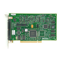
National Instruments DAQ PCI-1200 User Manual (100 pages)
DAQ Multifunctional I/O Board for PCI Bus Computers
Brand:
National Instruments
| Category:
Computer Hardware
| Size: 0.83 MB
Table of Contents
Important Information
3
Table of Contents
4
About this Manual
8
Organization of this Manual
8
Appendix B Customer Communication
8
Conventions Used in this Manual
9
National Instruments Documentation
10
Related Documentation
11
Customer Communication
11
Chapter 1 Introduction
12
About the PCI-1200
12
What You Need to Get Started
12
Figure
12
Unpacking
13
Software Programming Choices
13
National Instruments Application Software
13
NI-DAQ Driver Software
14
Register-Level Programming
15
Figure 1-1. the Relationship between the Programming Environment
15
Optional Equipment
16
Custom Cabling
16
Chapter 2 Installation and Configuration
18
Software Installation
18
Hardware Installation
18
Board Configuration
19
Analog I/O Configuration
19
Table 2-1. Analog I/O Settings
19
Analog Input Mode
20
Analog Input Polarity
20
Analog Output Polarity
20
NRSE Input (Eight Channels)
21
RSE Input (Eight Channels, Reset Condition)
21
Table 2-2. Analog Input Modes for the PCI-1200
21
DIFF Input (Four Channels)
22
Chapter 3 Signal Connections
23
I/O Connector
23
Figure
23
Figure 3-1. PCI-1200 I/O Connector Pin Assignments
24
Signal Connection Descriptions
24
Table 3-1. Signal Descriptions for PCI-1200 I/O Connector Pins
25
Analog Input Signal Connections
27
Table 3-2. Bipolar Analog Input Signal Range Versus Gain
27
Table 3-3. Unipolar Analog Input Signal Range Versus Gain
27
Figure 3-2. PCI-1200 Instrumentation Amplifier
28
Input Configurations
29
Table 3-4. Summary of Analog Input Connections
30
Differential Connection Considerations (DIFF Configuration)
31
Differential Connections for Grounded Signal Sources
32
Figure 3-3. Differential Input Connections for Grounded Signal Sources
32
Differential Connections for Floating Signal Sources
33
Figure 3-4. Differential Input Connections for Floating Sources
33
Single-Ended Connection Considerations
34
Figure 3-5. Single-Ended Input Connections for Floating Signal Sources
35
Single-Ended Connections for Floating Signal Sources (RSE Configuration)
35
Single-Ended Connections for Grounded Signal Sources (NRSE Configuration)
35
Common-Mode Signal Rejection Considerations
36
Figure 3-6. Single-Ended Input Connections for Grounded Signal Sources
36
Types of Signal Sources
29
Floating Signal Sources
29
Ground-Referenced Signal Sources
29
Analog Output Signal Connections
37
Digital I/O Signal Connections
38
Figure 3-7. Analog Output Signal Connections
38
Figure 3-8. Digital I/O Connections
39
Logical Inputs and Outputs
39
Port C Pin Connections
40
Power Connections
40
DAQ and General Purpose Timing Signal Connections
40
Table 3-5. Port C Signal Assignments
40
DAQ Timing Connections
41
Figure 3-9. EXTCONV* Signal Timing
41
Figure 3-10. Posttrigger DAQ Timing
42
Figure 3-11. Pretrigger DAQ Timing
43
Figure 3-12. Interval-Scanning Signal Timing
44
Figure 3-13. EXTUPDATE* Signal Timing for Updating DAC Output
45
General Purpose Timing Signal Connections
45
Figure 3-14. Event-Counting Application with External Switch Gating
46
Figure 3-15. Frequency Measurement Application
47
Figure 3-16. General Purpose Timing Signals
48
Table 3-6. Signal Names Used in Timing Diagrams
49
Timing Specifications
49
Figure 3-17. Mode 1 Timing Specifications for Input Transfers
50
Mode 1 Input Timing
50
Figure 3-18. Mode 1 Timing Specifications for Output Transfers
51
Mode 1 Output Timing
51
Figure 3-19. Mode 2 Timing Specifications for Bidirectional Transfers
52
Mode 2 Bidirectional Timing
52
Chapter 4 Theory of Operation
53
Functional Overview
53
PCI-1200 Block Diagram
53
Timing Circuitry
53
Analog Input Circuitry
53
Analog Output Circuitry
53
PCI Interface Circuitry
54
Digital I/O Circuitry
54
Timing
55
Analog Input
57
Analog Input Circuitry
58
DAQ Operations
59
Controlled Acquisition Mode
60
Freerun Acquisition Mode
60
Interval Scanning Acquisition Mode
60
Multichannel Scanned Data Acquisition
61
Single-Channel Data Acquisition
61
DAQ Rates
62
Table 4-1. Analog Input Settling Time Versus Gain
62
Table 4-2. PCI-1200 Maximum Recommended DAQ Rates
62
Analog Output
63
Analog Output Circuitry
63
DAC Timing
64
Digital I/O
64
Chapter 5 Calibration
67
Calibration at Higher Gains
67
Calibration Equipment Requirements
67
Using the Calibration Function
68
Appendix A Specifications
69
Input Characteristics
69
Bus Interface
77
Technical Support Form
80
Advertisement
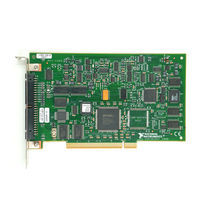
National Instruments DAQ PCI-1200 User Manual (93 pages)
DAC Multifunctional I/O Device for PCI Bus Computers
Brand:
National Instruments
| Category:
I/O Systems
| Size: 0.71 MB
Table of Contents
Table of Contents
4
About this Manual
7
Conventions Used in this Manual
7
National Instruments Documentation
8
Related Documentation
9
Chapter 1 Introduction
10
About the ni PCI-1200
10
What You Need to Get Started
10
Software Programming Choices
11
Ni-Daq
11
National Instruments ADE Software
12
Optional Equipment
12
Custom Cabling
13
Unpacking
13
Safety Information
14
Chapter 2 Installing and Configuring the ni PCI-1200
17
Installing the Software
17
Installing the Hardware
17
Configuring the Device
18
Analog I/O Configuration
18
Analog Input Polarity
19
Analog Output Polarity
19
Analog Input Mode
20
RSE Input Mode (Eight Channels, Reset Condition)
20
DIFF Input Mode (Four Channels)
21
NRSE Input Mode (Eight Channels)
21
Chapter 3 Signal Connections
22
I/O Connector
22
Signal Connection Descriptions
23
Analog Input Signal Connections
25
Floating Signal Sources
27
Types of Signal Sources
27
Ground-Referenced Signal Sources
28
Input Configurations
28
Differential Connection Considerations (DIFF Configuration)
30
Differential Connections for Grounded Signal Sources
31
Differential Connections for Floating Signal Sources
32
Single-Ended Connection Considerations
33
Single-Ended Connections for Floating Signal Sources (RSE Configuration)
34
Single-Ended Connections for Grounded Signal Sources (NRSE Configuration)
34
Common-Mode Signal Rejection Considerations
35
Analog Output Signal Connections
36
Digital I/O Signal Connections
37
Logical Inputs and Outputs
38
Port C Pin Connections
39
Power Connections
39
DAQ and General Purpose Timing Signal Connections
39
DAQ Timing Connections
40
General Purpose Timing Signal Connections
44
Timing Specifications
48
Mode 1 Input Timing
49
Mode 1 Output Timing
50
Mode 2 Bidirectional Timing
51
Chapter 4 Theory of Operation
52
Functional Overview
52
PCI Interface Circuitry
53
Timing
54
Analog Input
56
Analog Input Circuitry
57
DAQ Operations
58
Controlled Acquisition Mode
59
Freerun Acquisition Mode
59
Interval Scanning Acquisition Mode
59
Multichannel Scanned Data Acquisition
60
Single-Channel Data Acquisition
60
DAQ Rates
60
Analog Output
62
Analog Output Circuitry
62
DAC Timing
63
Digital I/O
63
Chapter 5 Calibration
64
Calibration at Higher Gains
65
Calibration Equipment Requirements
65
Using the Calibration Function
66
Appendix A Specifications
67
Advertisement
Related Products
National Instruments PCI-1407
National Instruments PCI-DIO-96
National Instruments PCI-8433
National Instruments PCI-CAN/2
National Instruments PCI-7041
National Instruments NI PCI-7830R
National Instruments PCI-5114
National Instruments PCI-6520
National Instruments PCI-8335
National Instruments PCI-6034E
National Instruments Categories
Control Unit
I/O Systems
Controller
Computer Hardware
Measuring Instruments
More National Instruments Manuals
Login
Sign In
OR
Sign in with Facebook
Sign in with Google
Upload manual
Upload from disk
Upload from URL