Sign In
Upload
Manuals
Brands
Motorola Manuals
Cell Phone
PRO Series
Motorola PRO Series Manuals
Manuals and User Guides for Motorola PRO Series. We have
13
Motorola PRO Series manuals available for free PDF download: Detailed Service Manual, Service Manual, User Manual, Manual, Basic Service Manual, Getting Started Manual
Motorola PRO Series Detailed Service Manual (639 pages)
Detailed service manual for Two-Way Radios
Brand:
Motorola
| Category:
Two-Way Radio
| Size: 31.13 MB
Table of Contents
Computer Software Copyrights
2
Disclaimer
2
Document Copyrights
2
Foreword
2
Product Safety and Rf Exposure Compliance
2
Trademarks
2
Document History
3
Table of Contents
5
List of Figures
9
Related Publications
19
FMRC Approved Equipment
21
Intrinsically Safe Radio Information
21
Repair of FMRC Approved Products
22
Do Not Substitute Options or Accessories
23
Chapter 1 Introduction
25
Scope of Manual
25
Warranty and Service Support
25
Piece Parts
26
Technical Support
26
Further Assistance from Motorola
26
Radio Model Chart and Specification
27
Radio Model Information
27
Chapter 2 Radio Power Distribution
29
Figure 2-1. DC Power Distribution Block Diagram
29
Chapter 3 Keypad
31
Figure 3-1. Keypad Block Diagram
31
Controller Board
32
Figure 3-2. Controller Block Diagram
32
Figure 3-3. RTC Circuit
33
Chapter 4 UHF Band 1 Theory of Operation
35
Transmitter
35
Figure 4-1. Transmitter Block Diagram
35
Antenna Matching Network
36
Antenna Switch
36
Harmonic Filter
36
Receiver
37
Figure 4-2. UHF Receiver Block Diagram
37
Frequency Generation Circuitry
38
Figure 4-3. Frequency Generation Unit Block Diagram
38
Synthesizer
39
Figure 4-4. Synthesizer Block Diagram
39
Voltage-Controlled Oscillator (VCO)
40
Figure 4-5. VCO Block Diagram
40
Chapter 5 UHF Band 2 Theory of Operation
43
Transmitter
43
Figure 5-1. Transmitter Block Diagram
43
Receiver
45
Figure 5-2. UHF Receiver Block Diagram
45
Frequency Generation Circuitry
46
Figure 5-3. Frequency Generation Unit Block Diagram
46
Synthesizer
47
Figure 5-4. Synthesizer Block Diagram
47
Voltage-Controlled Oscillator (VCO)
48
Figure 5-5. VCO Block Diagram
48
Chapter 6 VHF Theory of Operation
51
Transmitter
51
Figure 6-1. Transmitter Block Diagram
51
Receiver (for All Models Except those with PCB 8486473Z04)
53
Figure 6-2. VHF Receiver Block Diagram
53
Receiver (for Models with PCB 8486473Z04)
55
Figure 6-3. VHF Receiver Block Diagram
55
Frequency Generation Circuitry
58
Figure 6-4. Frequency Generation Unit Block Diagram
58
Synthesizer
59
Figure 6-5. Synthesizer Block Diagram
59
Voltage-Controlled Oscillator (VCO)
60
Figure 6-6. VCO Block Diagram
60
Chapter 7 Low Band, 800 Mhz, Passport & 900 Mhz Theory of Operation
63
Introduction
63
Low Band Transmitter
63
Figure 7-1. Low Band Transmitter Block Diagram
63
Low Band Receiver
65
Figure 7-2. Low Band Receiver Block Diagram
65
Synthesizer
67
Figure 7-3. Low Band Frequency Generation Unit Block Diagram
67
Voltage Control Oscillators (VCO)
68
Figure 7-4. Low Band Synthesizer Block Diagram
68
800 Mhz Transmitter
69
Figure 7-5. 800 Mhz Transmitter Block Diagram
69
800 Mhz Receiver
71
Synthesizer
74
Figure 7-8. 800 Mhz Frequency Generation Unit Block Diagram
74
Figure 7-9. 800 Mhz Synthesizer Block Diagram
75
Figure 7-10. 800 Mhz VCO Block Diagram
76
Trunked Radio Systems
77
Power Supplies
78
7.10 900 Mhz Transmitter
79
Figure 7-11. Transmitter Block Diagram
79
Power Amplifier
80
7.11 900 Mhz Receiver
81
Figure 7-12. 900 Mhz Receiver Block Diagram (for PCB No. 8485910Z01)
81
Figure 7-13. 900 Mhz Receiver Block Diagram (for PCB No. 8471203M01)
82
7.12 Frequency Generation Circuitry
86
7.13 900 Mhz Synthesizer
86
Figure 7-14. Frequency Generation Unit Block Diagram
86
Figure 7-15. Synthesizer Block Diagram
87
900 Mhz Voltage Control Oscillator (VCO)
88
Figure 7-16. VCO Block Diagram
88
Chapter 8 Maintenance
91
Introduction
91
Preventive Maintenance
91
Inspection
91
Safe Handling of CMOS and LDMOS
92
General Repair Procedures and Techniques
92
Recommended Test Tools
94
Replacing the Circuit Board Fuse
95
Figure 8-1. Uhf/Vhf/Low Band/800 Mhz/900 Mhz Circuit Board Fuse Locations
95
Removing and Reinstalling the Circuit Board
96
Figure 8-2. Circuit Board Removal and Reinstallation
96
Power up Self-Test Error Codes
97
8.10 UHF Band 1 Troubleshooting Charts
98
Troubleshooting Flow Chart for Transmitter
104
Troubleshooting Flow Chart for Synthesizer
105
Troubleshooting Flow Chart for Vco
106
8.11 UHF Band 2 Troubleshooting Charts
107
8.12 VHF Troubleshooting Charts
116
8.13 Low Band Troubleshooting Charts
125
8.14 800 Mhz Troubleshooting Charts
131
8.15 Passport Trunking Troubleshooting Chart
140
8.16 Keypad Troubleshooting Chart
141
8.17 900 Mhz Troubleshooting Charts
142
Advertisement
Motorola PRO Series Detailed Service Manual (686 pages)
Two-Way Mobile Radios
Brand:
Motorola
| Category:
Two-Way Radio
| Size: 25.49 MB
Table of Contents
Table of Contents
7
Chapter 1 Introduction
9
About this Manual
9
Scope
9
Organization
9
Conventions
9
Warranty and Service Support
9
Warranty Period and Return Instructions
10
After Warranty Period
10
Piece Parts Availability
10
Replacement Parts Ordering
10
Technical Support
11
Radio Model Information
11
Chapter 2 Maintenance
13
Introduction
13
Preventive Maintenance
13
Inspection
13
Cleaning
13
Safe Handling of CMOS and LDMOS
14
General Repair Procedures and Techniques
14
Parts Replacement and Substitution
15
Rigid Circuit Boards
15
Chip Components
15
Shields
16
Notes for All Schematics and Circuit Boards
17
Service Aids
23
Recommended Service Tools
23
Recommended Test Equipment
25
Chapter 1 Overview
29
CDM750 / PRO3100 Model (GCN6112_)
29
CDM1250 / PRO5100 Model (GCN6113_)
29
CDM1550 Series / PRO7100 Model (GCN6114_)
30
Data Radio Series (GCN6116_)
30
Introduction
31
Control Head (CDM750 / PRO3100)
31
Power Supplies
31
Power On/Off
31
Microprocessor Circuit
31
SBEP Serial Interface
32
Keypad Keys
32
Status LED and Back Light Circuit
33
Microphone Connector Signals
33
Speaker
34
Electrostatic Transient Protection
34
Control Head (CDM1250 / PRO5100 / CDM1550 Series / PRO7100)
34
Power Supplies
34
Power On/Off
34
Microprocessor Circuit
34
SBEP Serial Interface
35
Keypad Keys
35
Status LED and Back Light Circuit
36
Liquid Crystal Display (LCD)
36
Microphone Connector Signals
37
Speaker
37
Electrostatic Transient Protection
37
Passport Trunking Controller Board (PTCB)
38
Chapter 3 Troubleshooting Charts
39
Control Head CDM750 / PRO3100 Troubleshooting Flow Charts
39
Troubleshooting Flow Chart for On/Off
41
Control Head CDM1250 / PRO5100 / CDM1550 Series / PRO7100
41
Troubleshooting Flow Charts
41
Troubleshooting Flow Chart for Microprocessor
42
Troubleshooting Flow Chart for Display
43
Troubleshooting Flow Chart for Back Light
44
Control Head CDM750 / PRO3100 PCB 8486146B07, Schematics, and Parts Lists
47
Control Head CDM1250 / PRO5100 / CDM1550 Series / PRO7100 PCB 8486155B06, Schematics, and Parts Lists
51
Theory of Operation
59
Controller Circuits
59
Overview
59
General
59
Radio Power Distribution
60
Electronic ON/OFF
62
Emergency
62
Mechanical ON/OFF
63
Ignition
63
Microprocessor Clock Synthesizer
63
Serial Peripheral Interface (SPI)
64
SBEP Serial Interface
65
General Purpose Input/Output
65
Normal Microprocessor Operation
66
FLASH Electronically Erasable Programmable Memory (FLASH EEPROM)3:1
67
Electrically Erasable Programmable Memory (EEPROM)
67
Static Random Access Memory (SRAM)
68
Controller Board Audio and Signaling Circuits
68
Audio Signaling Filter IC with Compander (ASFIC CMP)
68
Transmit Audio Circuits
69
Transmit Signaling Circuits
71
Receive Audio Circuits
73
Receive Signaling Circuits
76
Voice Storage (Optional)
77
Troubleshooting Charts
79
Troubleshooting Flow Chart for Controller
79
Allocation of Schematics and Circuit Boards
81
Controller Circuits
81
Voice Storage Facility
81
Controller T2 Schematics and Parts Lists
85
Controller T5 Schematics and Parts Lists
92
Controller T6/T7/T9 Schematics and Parts Lists
100
VHF (136-174 Mhz) 1-25W Model Charts
149
CDM Series Model Chart
149
PRO Series Model Chart
150
Technical Specifications
151
Chapter 2 Theory of Operation
153
Introduction
153
VHF (136-174 Mhz) 1-25W Receiver Front-End
153
Receiver Front-End
153
Front-End Bandpass Filters and Pre-Amplifier
154
First Mixer and High Intermediate Frequency
154
Low Intermediate Frequency (IF) and Receiver Back-End
154
VHF (136-174 Mhz) 1-25W Transmitter Power Amplifier
156
Power Controlled Driver Stage
156
Final Stage
156
Directional Coupler
156
Antenna Switch
157
Harmonic Filter
157
Power Control
157
VHF (136-174 Mhz) 1-25W Frequency Synthesis
157
Reference Oscillator
158
Fractional-N Synthesizer
158
Voltage Controlled Oscillator (VCO)
159
Synthesizer Operation
160
Chapter 3 Troubleshooting Charts
161
Troubleshooting Flow Chart for Receiver
161
Troubleshooting Flow Chart for 25 W Transmitter
165
Troubleshooting Flow Chart for Synthesizer
166
Troubleshooting Flow Chart for VCO
167
VHF (136-174 Mhz) 1-25 W LDMOS PCB 8471235L04, Schematics, and
173
VHF (136-174 Mhz) 1-25 W PCB 8486172B04, Schematics, and
180
VHF (136-174 Mhz) 1-25 W PCB 8486172B06, Schematics, and
190
VHF (136-174 Mhz) 1-25 W PCB 8486172B07, Schematics, and Parts Lists
200
VHF (136-174 Mhz) 1-25 W PCB 8486172B08, Schematics, and Parts Lists
207
VHF (136-174 Mhz) 1-25 W PCB 8471235L06 Schematics, and Parts Lists
215
PRO Series Model Chart
294
Technical Specifications
294
Chapter 2 Theory of Operation
297
Introduction
297
UHF Band 2 (450-512/527 Mhz) 1-25W Receiver Front-End
297
Receiver Front-End
297
Front-End Bandpass Filters and Pre-Amplifier
298
First Mixer and High Intermediate Frequency
298
UHF Band 2 (450-512/527 Mhz) 1-25 W Transmitter Power Amplifier
299
First Power Controlled Stage
300
Power Controlled Driver Stage
300
Final Stage
300
Directional Coupler
301
Antenna Switch
301
Harmonic Filter
301
Power Control
301
UHF Band 2 (450-512/527 Mhz) 1-25 W Frequency Synthesis
302
Reference Oscillator
303
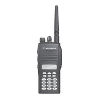
Motorola PRO Series Service Manual (146 pages)
Professional Series Two-Way Portable Radios
Brand:
Motorola
| Category:
Portable Radio
| Size: 2.27 MB
Table of Contents
Table of Contents
7
Foreword
6
Manual Revisions
6
Computer Software Copyrights
6
Document Copyrights
6
Disclaimer
6
Trademarks
6
Table of Contents
7
List of Figures
15
Chapter 9 Schematic Diagrams, Overlays, and Parts Lists
15
Keypad-Controller Interconnect Flex Schematic
15
List of Figures
15
UHF Band
18
Intrinsically Safe Radio Information
23
FMRC Approved Equipment
23
Relabeling
24
Repair
24
Repair of FMRC Approved Products
24
Do Not Substitute Options or Accessories
25
Chapter 1 Introduction
27
Scope of Manual
27
Warranty and Service Support
27
After Warranty Period
27
Return Instructions
27
Warranty Period
27
Related Documents
28
Technical Support
28
Piece Parts Availability
28
Radio Model Chart and Specifications
29
Radio Model Information
29
Chapter 2 Radio Power Distribution
31
Figure 2-1. DC Power Distribution Block Diagram
31
Chapter 3 Keypad
33
Controller Board
33
Figure 3-1. Keypad Block Diagram
33
Figure 3-2. Controller Block Diagram
34
MCU Digital
34
Real Time Clock
34
Circuit Description
35
Figure 3-3. RTC Circuit
35
MODB/VSTBY Supply
35
Audio/Signaling
36
Chapter 4 UHF Band 1 Theory of Operation
37
Transmitter
37
Figure 4-1. Transmitter Block Diagram
37
General
37
Power Amplifier
37
Antenna Matching Network
38
Antenna Switch
38
Harmonic Filter
38
Power Control Integrated Circuit (PCIC)
38
Receiver
39
Figure 4-2. UHF Receiver Block Diagram
39
Receiver Front-End
39
Receiver Back-End
40
Frequency Generation Circuitry
40
Figure 4-3. Frequency Generation Unit Block Diagram
40
Synthesizer
41
Figure 4-4. Synthesizer Block Diagram
41
Voltage-Controlled Oscillator (VCO)
42
Figure 4-5. VCO Block Diagram
42
Chapter 5 UHF Band 2 Theory of Operation
45
Transmitter
45
Figure 5-1. Transmitter Block Diagram
45
General
45
Power Amplifier
45
Antenna Matching Network
46
Antenna Switch
46
Harmonic Filter
46
Power Control Integrated Circuit (PCIC)
46
Receiver
47
Figure 5-2. UHF Receiver Block Diagram
47
Receiver Front-End
47
Receiver Back-End
48
Frequency Generation Circuitry
48
Figure 5-3. Frequency Generation Unit Block Diagram
48
Synthesizer
49
Figure 5-4. Synthesizer Block Diagram
49
Voltage-Controlled Oscillator (VCO)
50
Figure 5-5. VCO Block Diagram
50
Chapter 6 VHF Theory of Operation
53
Transmitter
53
Figure 6-1. Transmitter Block Diagram
53
General
53
Power Amplifier
53
Antenna Matching Network
54
Antenna Switch
54
Harmonic Filter
54
Power Control Integrated Circuit (PCIC)
54
Receiver (for All Models Except those with PCB 8486473Z04)
55
Figure 6-2. VHF Receiver Block Diagram
55
Receiver Front-End
55
Automatic Gain Control Circuit
56
Receiver Back-End
56
Receiver (for Models with PCB 8486473Z04)
57
Figure 6-3. VHF Receiver Block Diagram
57
Receiver Back-End
58
Receiver Front-End
58
Automatic Gain Control Circuit
59
Frequency Generation Circuitry
60
Figure 6-4. Frequency Generation Unit Block Diagram
60
Synthesizer
61
Figure 6-5. Synthesizer Block Diagram
61
Voltage-Controlled Oscillator (VCO)
62
Figure 6-6. VCO Block Diagram
62
Chapter 7 Low Band, 800 Mhz, Passport & 900 Mhz Theory of Operation
65
Introduction
65
Low Band Transmitter
65
Figure 7-1. Low Band Transmitter Block Diagram
65
Power Amplifier (PA)
65
Antenna Matching Transformer
66
Antenna Switch
66
Electrostatic Discharge (ESD) Protection Circuit
66
Harmonic Filter
66
Power Control Integrated Circuit (PCIC)
66
Temperature Cut Back Circuit
66
Low Band Receiver
67
Figure 7-2. Low Band Receiver Block Diagram
67
Receiver Front-End
67
Automatic Gain Control (AGC)
68
Frequency Generation Circuit
68
Receiver Back-End
68
Synthesizer
69
Figure 7-3. Low Band Frequency Generation Unit Block Diagram
69
Voltage Control Oscillators (VCO)
70
Buffer
70
Figure 7-4. Low Band Synthesizer Block Diagram
70
Receive VCO
70
Transmit VCO
70
Diplexer/Output Filters
71
Prescalar Feedback
71
800 Mhz Transmitter
71
Figure 7-5. 800 Mhz Transmitter Block Diagram
71
Power Amplifier
71
Antenna Switch
72
Harmonic Filter
72
Power Control Integrated Circuit (PCIC)
72
800 Mhz Receiver
73
Figure 7-6. 800 Mhz Receiver Block Diagram
73
Receiver Front-End
73
Automatic Gain Control Circuit
74
Receiver Back-End
74
Figure 7-7. 800 Mhz Frequency Generation Unit Block Diagram
75
Frequency Generation Circuit
75
Synthesizer
76
Figure 7-8. 800 Mhz Synthesizer Block Diagram
76
Figure 7-9. 800 Mhz VCO Block Diagram
77
Voltage Control Oscillator (VCO)
77
Trunked Radio Systems
78
LTR™ Trunked Systems
78
MPT Trunked Systems
78
Privacy Plus Trunked Systems
78
Keyboard Circuit
79
Low Speed Data Filter
79
Microcontroller (MCU)
79
Passport™ Trunked Systems
79
Power Supplies
79
Backlight Driver and Led's
80
Voice Storage
80
900 Mhz Transmitter
80
Figure 7-10. Transmitter Block Diagram
80
Antenna Switch
81
Harmonic Filter
81
Power Amplifier
81
Power Control Integrated Circuit (PCIC)
81
900 Mhz Receiver
82
Figure 7-11. 900 Mhz Receiver Block Diagram
82
Receiver Front-End
82
Hear Clear IC
83
Receiver Back-End
83
Automatic Gain Control Circuit
84
Hear Clear Routing of Data/Signaling
84
Receive Path for Radios with Hear Clear
84
Frequency Generation Circuitry
85
Figure 7-12. Frequency Generation Unit Block Diagram
85
900 Mhz Synthesizer
86
Figure 7-13. Synthesizer Block Diagram
87
900 Mhz Voltage Control Oscillator (VCO)
88
Figure 7-14. VCO Block Diagram
88
Chapter 8 Maintenance
91
Introduction
91
Preventive Maintenance
91
Inspection
91
Cleaning
91
Safe Handling of CMOS and LDMOS
92
General Repair Procedures and Techniques
92
Recommended Test Tools
94
Replacing the Circuit Board Fuse
95
Figure 8-1. Uhf/Vhf/Low Band/800 Mhz/900 Mhz Circuit Board Fuse Locations
96
Removing and Reinstalling the Circuit Board
97
Power up Self-Test Error Codes
97
Figure 8-2. Circuit Board Removal and Reinstallation
97
UHF Band 1 Troubleshooting Charts
99
Troubleshooting Flow Chart for Controller for All Models Except
99
Troubleshooting Flow Chart for Controller for Models with PCB 8486458Z03
100
PCB 8486458Z03 (Sheet 1 of 2)
101
Troubleshooting Flow Chart for Receiver for All Models Except
101
PCB 8486458Z03 (Sheet 2 of 2)
102
Troubleshooting Flow Chart for Receiver for All Models Except
102
Troubleshooting Flow Chart for Receiver, for Models with PCB 8486458Z03 (Sheet 1 of 2)
103
Troubleshooting Flow Chart for Receiver, for Models with PCB 8486458Z03 (Sheet 2 of 2)
104
Troubleshooting Flow Chart for Transmitter
105
Troubleshooting Flow Chart for Synthesizer
106
Troubleshooting Flow Chart for VCO
107
UHF Band 2 Troubleshooting Charts
108
Pcb 8486686Z02
108
Troubleshooting Flow Chart for Controller for All Models
108
Troubleshooting Flow Chart for Controller for Models with PCB 8486686Z02
109
Troubleshooting Flow Chart for Receiver, for All Models Except those with PCB 8486686Z02 (Sheet 1 of 2)
110
Troubleshooting Flow Chart for Receiver, for All Models Except those with PCB 8486686Z02 (Sheet 2 of 2)
111
Troubleshooting Flow Chart for Receiver, for Models with PCB 8486686Z02 (Sheet 1 of 2)
112
Troubleshooting Flow Chart for Receiver, for Models with PCB 8486686Z02 (Sheet 2 of 2)
113
Troubleshooting Flow Chart for Transmitter
114
Troubleshooting Flow Chart for Synthesizer
115
Troubleshooting Flow Chart for VCO
116
VHF Troubleshooting Charts
117
Troubleshooting Flow Chart for Controller for All Models
117
Troubleshooting Flow Chart for Controller for Models with PCB 8486473Z04
118
Except those with PCB 8486473Z04
119
Troubleshooting Flow Chart for Receiver, for All Models
119
Troubleshooting Flow Chart for Receiver, for All Models Except those with PCB 8486473Z04 (Sheet 1 of 2)
119
Troubleshooting Flow Chart for Receiver, for All Models Except those with PCB 8486473Z04 (Sheet 2 of 2)
120
Troubleshooting Flow Chart for Receiver for Models with PCB 8486473Z04 (Sheet 1 of 2)
121
Troubleshooting Flow Chart for Receiver for Models with PCB 8486473Z04 (Sheet 2 of 2)
122
Troubleshooting Flow Chart for Transmitter
123
Troubleshooting Flow Chart for Synthesizer
124
Troubleshooting Flow Chart for VCO
125
Low Band Troubleshooting Charts
126
Troubleshooting Flow Chart for Controller
126
Troubleshooting Flow Chart for Receiver (Sheet 1 of 2)
127
Troubleshooting Flow Chart for Receiver (Sheet 2 of 2)
128
Troubleshooting Flow Chart for Transmitter
129
Troubleshooting Flow Chart for Synthesizer
130
Troubleshooting Flow Chart for VCO
131
800 Mhz Troubleshooting Charts
132
Troubleshooting Flow Chart for Controller
132
Troubleshooting Flow Chart for Receiver (Sheet 1 of 2)
133
Troubleshooting Flow Chart for Receiver (Sheet 2 of 2)
134
Troubleshooting Flow Chart for Transmitter
135
Troubleshooting Flow Chart for Synthesizer
136
Troubleshooting Flow Chart for VCO
137
Passport Trunking Troubleshooting Chart
138
Keypad Troubleshooting Chart
139
Mhz Troubleshooting Charts
140
Troubleshooting Flow Chart for Controller (Sheet 2 of 2)
141
Troubleshooting Flow Chart for Receiver (Sheet 1 of 2)
142
Troubleshooting Flow Chart for Receiver (Sheet 2 of 2)
143
Troubleshooting Flow Chart for VCO
146
Advertisement
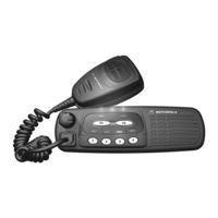
Motorola PRO Series Service Manual (178 pages)
CDM/PRO Series Professional Series Two-Way Mobile Radios
Brand:
Motorola
| Category:
Two-Way Radio
| Size: 6.09 MB
Table of Contents
Chapter 1: Service Maintainability
5
Table of Contents
5
About this Manual
7
Scope
7
Organization
7
Conventions
7
Introduction
7
Warranty and Service Support
7
Warranty Period and Return Instructions
8
After Warranty Period
8
Piece Parts Availability
8
Replacement Parts Ordering
8
Technical Support
9
Radio Model Information
9
Maintenance
11
Introduction
11
Preventive Maintenance
11
Inspection
11
Cleaning
11
General Repair Procedures and Techniques
12
Parts Replacement and Substitution
12
Rigid Circuit Boards
12
Chip Components
13
Shields
13
Safe Handling of CMOS and LDMOS
12
Notes for All Schematics and Circuit Boards
14
Service Aids
19
Recommended Service Tools
19
Recommended Test Equipment
21
Chapter 2: Control Head Service Information
23
CDM1250 / PRO5100 Model (GCN6113_)
25
CDM750 / PRO3100 Model (GCN6112_)
25
Overview
25
CDM1550 Series / PRO7100 Model (GCN6114_)
26
Theory of Operation
27
Control Head (CDM750 / PRO3100)
27
Power Supplies
27
Power On/Off
27
Microprocessor Circuit
27
SBEP Serial Interface
28
Keypad Keys
28
Status LED and Back Light Circuit
29
Microphone Connector Signals
29
Speaker
29
Electrostatic Transient Protection
30
Introduction
27
Control Head (CDM1250 / PRO5100 / CDM1550 Series / PRO7100)
30
Power Supplies
30
Power On/Off
30
Microprocessor Circuit
30
SBEP Serial Interface
31
Keypad Keys
31
Status LED and Back Light Circuit
32
Liquid Crystal Display (LCD)
32
Microphone Connector Signals
33
Speaker
33
Electrostatic Transient Protection
33
Passport Trunking Controller Board (PTCB)
34
Troubleshooting Charts
35
Control Head CDM750 / PRO3100 Troubleshooting Flow Charts
35
Troubleshooting Flow Chart for On/Off
35
Troubleshooting Flow Chart for Microprocessor
36
Control Head CDM1250 / PRO5100 / CDM1550 Series / PRO7100 Troubleshooting Flow Charts
37
Troubleshooting Flow Chart for On/Off
37
Troubleshooting Flow Chart for Microprocessor
38
Troubleshooting Flow Chart for Display
39
Troubleshooting Flow Chart for Back Light
40
Allocation of Schematics and Circuit Boards
42
Control Head CDM750 / PRO3100 PCB 8486146B07, Schematics, and Parts Lists
43
Control Head CDM1250 / PRO5100 / CDM1550 Series / PRO7100 PCB 8486155B06, Schematics, and Parts Lists
47
Motorola PRO Series Service Manual (180 pages)
Professional Series Two-Way Mobile Radios
Brand:
Motorola
| Category:
Two-Way Radio
| Size: 6.59 MB
Table of Contents
Kdswhu 6Huylfh 0Dlqwdlqdelolw\ 7Deoh Ri &Rqwhqwv
7
Table of Contents
7
Erxw Wklv 0Dqxdo
9
Duudqw\ Dqg 6Huylfh 6Xssruw
9
Duudqw\ 3Hulrg Dqg 5Hwxuq ,Qvwuxfwlrqv
10
Iwhu :Duudqw\ 3Hulrg
10
Lhfh 3Duwv $Ydlodelolw
10
Hsodfhphqw 3Duwv 2Ughulqj
10
Hfkqlfdo 6Xssruw
11
Dglr 0Rgho ,Qirupdwlrq
11
Uhyhqwlyh 0Dlqwhqdqfh
13
Hqhudo 5Hsdlu 3Urfhgxuhv Dqg 7Hfkqltxhv
14
Duwv 5Hsodfhphqw Dqg 6Xevwlwxwlrq
14
Ljlg &Lufxlw %Rdugv
14
Kls &Rpsrqhqwv
15
Rwhv )Ru $Oo 6Fkhpdwlfv Dqg &Lufxlw %Rdugv
16
Hfrpphqghg 6Huylfh 7Rrov
21
Hfrpphqghg 7Hvw (Txlsphqw)
23
Kdswhu 9+) 0+] : 6Huylfh ,Qirupdwlrq 7Deoh Ri &Rqwhqwv
123
Hfkqlfdo 6Shflilfdwlrqv
126
Hfhlyhu )Urqw(Qg
129
Hulhv 0Rgho &Kduw
126
Rz ,Qwhuphgldwh )Uhtxhqf\ ,) Dqg 5Hfhlyhu %Dfn(Qg
130
Urqw(Qg %Dqgsdvv )Lowhuv Dqg 3Uh$Psolilhu
130
Luvw 3Rzhu &Rqwuroohg 6Wdjh
131
Lqdo 6Wdjh
132
Luhfwlrqdo &Rxsohu
132
Rzhu &Rqwuroohg 'Ulyhu 6Wdjh
132
Qwhqqd 6Zlwfk
133
Duprqlf )Lowhu
133
Rzhu &Rqwuro
133
Hihuhqfh 2Vfloodwru
134
Udfwlrqdo1 6\Qwkhvl]Hu
134
Urxeohvkrrwlqj )Orz &Kduw Iru 6\Qwkhvl]Hu
142
Motorola PRO Series Detailed Service Manual (96 pages)
Professional Series Two-Way Portable Radios
Brand:
Motorola
| Category:
Two-Way Radio
| Size: 2.32 MB
Table of Contents
Revision Change
1
Fmr-2045A
2
Table of Contents
3
Chapter 1 UHF Theory of Operation
7
Transmitter
7
General
7
Power Amplifier
7
Transmitter Block Diagram
7
Antenna Switch
8
Harmonic Filter
8
Antenna Matching Network
8
Power Control Integrated Circuit (PCIC)
8
Receiver
9
Receiver Front-End
9
UHF Receiver Block Diagram
9
Receiver Back-End
10
Frequency Generation Circuitry
10
Frequency Generation Unit Block Diagram
10
Synthesizer
11
Synthesizer Block Diagram
11
Voltage-Controlled Oscillator (VCO)
12
VCO Block Diagram
12
Chapter 2 UHF Circuit Board Layouts, Schematic Diagrams and Parts List
15
Notes for All Schematics and Circuit Boards
15
Circuit Board/Schematic Diagrams and Parts List
17
UHF (403-470Mhz) Main Board Top Side PCB No. 8486458Z02
17
UHF (403-470Mhz) Main Board Bottom Side PCB No. 8486458Z02
18
UHF Controls and Switches Schematic Diagram
19
UHF Receiver Front-End Schematic Diagram
20
UHF Receiver Back-End Schematic Diagram
21
UHF Synthesizer Schematic Diagram
22
UHF Voltage Controlled Oscillator Schematic Diagram
23
UHF Harmonic Filter Schematic Diagram
24
UHF Transmitter Schematic Diagram
25
Controller ASFIC/ON_OFF Schematic Diagram
30
Chapter 3 UHF Troubleshooting Charts
31
Troubleshooting Flow Chart for Controller
31
Troubleshooting Flow Chart for Receiver (Sheet 1 of 2)
32
Troubleshooting Flow Chart for Receiver (Sheet 2 of 2)
33
Troubleshooting Flow Chart for Transmitter
34
Troubleshooting Flow Chart for Synthesizer
35
Troubleshooting Flow Chart for VCO
36
Chapter 4 UHF Band 2 Theory of Operation
37
Transmitter
37
General
37
Power Amplifier
37
Transmitter Block Diagram
37
Antenna Switch
38
Harmonic Filter
38
Antenna Matching Network
38
Power Control Integrated Circuit (PCIC)
38
Receiver
39
Receiver Front-End
39
UHF Receiver Block Diagram
39
UHF Band 2 Receiver Front End Schematic Diagram
39
Receiver Back-End
40
Frequency Generation Circuitry
40
Frequency Generation Unit Block Diagram
40
UHF Band 2 Receiver Back End Schematic Diagram
40
Synthesizer
41
Synthesizer Block Diagram
41
Voltage-Controlled Oscillator (VCO)
42
VCO Block Diagram
42
Motorola PRO Series Service Manual (122 pages)
Professional Series Two-Way Portable Radio
Brand:
Motorola
| Category:
Two-Way Radio
| Size: 3.25 MB
Table of Contents
Swb
19
VDDD
19
Int_Ext_Vdd
19
Key_Int
20
VDDD
21
Table of Contents
105
Ptt
119
Vs_Int
119
Reset
119
Pg7_R_W
119
Gnd
119
Motorola PRO Series User Manual (70 pages)
smartphone
Brand:
Motorola
| Category:
Cell Phone
| Size: 12.64 MB
Table of Contents
Your Phone
4
Table of Contents
5
Llet's Go
5
Touchscreen & Keys
7
Text Entry
9
Home Screen
11
Social Networking
14
Calls
15
Contacts
18
Messaging
21
Web
24
Location
26
Youtube
28
Apps & UPDATES
29
Bluetooth™ Wireless
31
Wi-Fi
33
Dlna
35
Tips & Tricks
35
Personalize
37
Photos & Videos
39
Music
42
Memory Card & File Transfer
47
Tools
49
Management
53
Security
55
Troubleshooting
57
Service & Repairs
57
Safety, Regulatory & Legal
58
Caution about High Volume Usage
59
Repetitive Motion
59
Glass Parts
59
Operational Warnings
59
Driving Precautions
59
Implantable Medical Devices
60
Regulatory Information
61
Industry Canada Notice to Users
62
Fcc Notice to Users
62
Your Location
62
Emergency Calls
62
Smart Practices While Driving
63
Content Copyright
65
California Perchlorate Label
65
Software Copyright Notice
65
Hearing Aid Compatibility with Mobile Phones
65
Open Source Software Information
66
Motorola Limited Warranty for the United States and Canada
66
What Does this Warranty Cover
66
Export Law Assurances
66
Products and Accessories
66
Product Registration
66
Who Is Covered
67
What will Motorola Do
67
What Other Limitations Are There
68
Motorola PRO Series User Manual (72 pages)
Brand:
Motorola
| Category:
Cell Phone
| Size: 30.77 MB
Table of Contents
Your Phone
4
Table of Contents
5
Let's Go
5
Touchscreen & Keys
8
Home Screen
10
Social Networking
13
Calls
15
Contacts
18
Messaging
21
Text Entry
24
Web
26
Location
28
Youtube
30
Apps & Updates
31
Bluetooth™ Wireless
33
Wireless
34
Dlna
36
Tips & Tricks
37
Personalise
39
Photos & Videos
40
Music
43
Set up Music
45
Memory Card & File Transfer
49
Tools
51
Management
54
Security
56
Troubleshooting
59
Safety, Regulatory & Legal
60
Repetitive Motion
61
Glass Parts
61
Operational Warnings
61
Caution about High Volume Usage
61
Potentially Explosive Areas
61
Follow Instructions to Avoid Interference Problems
62
Fcc Notice to Users
64
Your Location
64
Emergency Calls
64
Smart Practices While Driving
65
Software Copyright Notice
67
Open Source Software Information
67
Content Copyright
67
Warranty Information
68
How to Get Warranty Service
68
What Is Not Covered by the Warranty
69
Motorola PRO Series Manual (72 pages)
with MOTOBLUR
Brand:
Motorola
| Category:
Cell Phone
| Size: 7.66 MB
Table of Contents
Your Phone
4
Table of Contents
5
Let's Go
5
Touchscreen & Keys
8
Home Screen
10
Social Networking
13
Calls
15
Contacts
18
Messaging
21
Text Entry
24
Web
26
Location
28
Youtube
30
Apps & Updates
31
Bluetooth™ Wireless
33
Wi-Fi
34
Dlna
36
Tips & Tricks
37
Personalize
39
Photos & Videos
40
Music
43
Memory Card & File Transfer
49
Tools
51
Management
55
Security
56
Troubleshooting
59
Service & Repairs
60
Safety, Regulatory & Legal
61
Caution about High Volume Usage
62
Potentially Explosive Atmospheres
62
Operational Warnings
62
Glass Parts
62
Repetitive Motion
62
Rf Energy Operational Precautions
63
Implantable Medical Devices
63
Fcc Notice to Users
65
Your Location
65
Emergency Calls
66
Smart Practices While Driving
66
Open Source Software Information
68
Software Copyright Notice
68
Content Copyright
68
Motorola PRO Series Basic Service Manual (30 pages)
PRO Series
Brand:
Motorola
| Category:
Portable Radio
| Size: 2.74 MB
Table of Contents
Chapter 4 Transceiver Performance Testing
2
General
2
Antennas
2
Batteries
4
Table of Contents
6
Chapter 1 Introduction
10
Scope of Manual
10
Warranty and Service Support
10
Warranty Period and Return Instructions
10
After Warranty Period
10
Piece Parts Availability
11
Technical Support
12
Warranty and Repairs
12
Radio Model Information
13
Intrinsically Safe Radio Information
14
FMRC Approved Equipment
14
Repair of FMRC Approved Products
15
Repair
15
Relabeling
15
Do Not Substitute Options or Accessories
15
Chapter 3 Maintenance
17
Introduction
17
Preventive Maintenance
17
Inspection
17
Cleaning Procedures
17
Option Boards
17
Safe Handling of CMOS and LDMOS Devices
18
Repair Procedures and Techniques - General
18
Disassembling and Reassembling the Radio - General
19
Radio Disassembly - Detailed
20
Front Cover from Chassis Disassembly
20
Chassis Assembly Disassembly
22
Keypad and Keypad/Option Board Disassembly
23
Display Disassembly
24
Speaker, Microphone, and Universal Connector Flex Disassembly
24
PTT Disassembly
26
Control Top Disassembly
26
Radio Reassembly - Detailed
26
Control Top Reassembly
26
PTT Reassembly
26
Speaker, Microphone, and Universal Connector Flex Reassembly
27
Keypad and Keypad Option Board Reassembly
27
Chassis Assembly Reassembly
28
Chassis and Front Cover Reassembly
28
Option Board Installation
30
MOTOROLA PRO Series Getting Started Manual (2 pages)
Brand:
MOTOROLA
| Category:
Cell Phone
| Size: 13.51 MB
Motorola PRO Series Getting Started Manual (2 pages)
Brand:
Motorola
| Category:
Cell Phone
| Size: 13.23 MB
Advertisement
Related Products
Motorola Profile
Motorola pro
MOTOROLA PRO XT610
Motorola PC850
MOTOROLA PHOTON 4G
Motorola Timeport P8167
Motorola TimePort P7389i
Motorola PAZR V
Motorola P6KU1
Motorola PAYM0002SE
Motorola Categories
Cell Phone
Two-Way Radio
Baby Monitor
Cordless Telephone
Radio
More Motorola Manuals
Login
Sign In
OR
Sign in with Facebook
Sign in with Google
Upload manual
Upload from disk
Upload from URL