Sign In
Upload
Manuals
Brands
Milnor Manuals
Washer
MWF100C7
Milnor MWF100C7 Manuals
Manuals and User Guides for Milnor MWF100C7. We have
4
Milnor MWF100C7 manuals available for free PDF download: Installation And Service, Manual
Milnor MWF100C7 Manual (90 pages)
Brand:
Milnor
| Category:
Washer
| Size: 5.89 MB
Table of Contents
English
8
Table of Contents
8
Machine Data Plate
11
Figure 1 Machine Data Plate
11
Machine Description and Identification
11
Machine Identification
11
Description
11
About this Manual and Your Milnor® Machine
11
Safety
12
Tilting Washer Extractors
12
Safety Alert Messages-Internal Electrical and Mechanical Hazards
12
Safety Alert Messages-Cylinder and Processing Hazards
13
Safety Alert Messages-Unsafe Conditions
14
Damage and Malfunction Hazards
14
Hazards Resulting from Inoperative Safety Devices
14
Hazards Resulting from Damaged Mechanical Devices
15
Careless Use Hazards
15
Careless Operation Hazards-Vital Information for Operator Personnel (See also Operator Hazards Throughout Manual)
15
Careless Servicing Hazards-Vital Information for Service Personnel (See also Service Hazards Throughout Manuals)
16
Incorrect Configuration or Connection of Equipment
17
Prevent Damage from Chemical Supplies and Chemical Systems
17
Dangerous Chemical Supplies and Wash Formulas
17
How Chemical Supplies Can Cause Damage
17
Figure 2 Incorrect Configurations that Let the Chemical Supply Go in the Ma
18
Equipment and Procedures that Can Prevent Damage
19
Use the Chemical Manifold Supplied
19
Figure 3 Incorrect Configurations that Let the Chemical Supply Go in the Ma
19
Figure 4 Examples of Manifolds for Chemical Tubes. Your Equipment Can Look
19
Close the Line
20
Do Not Let a Vacuum Occur
20
Flush the Chemical Tube with Water
20
Put the Chemical Tube Fully below the Inlet
20
Prevent Leaks
20
Use the Red Safety Supports for Maintenance - MWF_C_, MWF_Y
20
What Safety Supports Are Provided and Why
20
Figure 5 a Configuration that Prevents Flow in the Machine When the Pump Is off (if the Chemical Tube and Tank Have no Pressure)
20
How to Deploy the Safety Stands
21
Maintenance Summary
22
Routine Maintenance
22
Guards and Related Components
23
Filters, Screens, and Sensitive Components
23
Table 1 Guards and Related Components
23
Table 2 Filters, Screens, and Sensitive Components
23
Table 4 Components that Become Worn
24
Table 3 Fluid Containers
24
Bearings and Bushings
24
Components that Become Worn
24
Fluid Containers
24
Motor Grease Schedule
25
Mechanisms and Settings
25
Table 5 Bearings and Bushings
25
Table 6 Motor Grease Schedule
25
Table 7 Mechanisms and Settings
25
How to Remove Contamination
26
Table 8 Contamination Types, Cleaning Agents, and Procedures
26
Table 9 Lubricant Identification
27
Lubricant Identification
27
Grease Gun Procedures
28
Procedures for Bearing Components Connected to a Grease Plate
28
Procedures for Motors
29
Figure 6 Motor Grease Maintenance Conditions
30
How to Show the Maintenance on a Calendar
31
Table 10 Motor Grease Intervals and Quantities
31
Table 11 Where to Put Marks on a Calendar
32
Figure 7 Belt and Pulley Conditions to Look for
32
How to Examine V-Belts and Pulleys
32
Maintenance Components-Machines and Controls Group
32
Figure 8 How to Adjust Belt Tension on a Machine that Uses Spring Tension
33
Inverters
34
Chemical Devices
34
Figure 9 Electric Box and Inverter. These Are Examples. Your Machine Can Look
34
Water and Steam Devices
35
Figure 10 Chemical Inlet Manifolds for Chemical Pump Systems. See Caution
35
Figure 11 Soap Chute and Optional 5-Compartment Supply Injector. These Are Ex
35
Figure 13 Steam Inlet Strainer. These Are Examples. Your Machine Can Look Different
36
Figure 12 Water Pressure Regulator for Chemical Flush. These Are Examples
36
How to Examine Compressed Air Mechanisms
36
Figure 14 Compressed Air Inlet Strainers. These Are Examples. Your Machine Can Look Different
37
Figure 15. Self-Purging Air Line Filter to Remove Moisture and Other Contamination. These Are Examples. Your Machine Can Look Different
37
Figure 16 Compressed Air Mechanisms These Are Examples. Your Machine Can Look Different
38
Photoeyes and Proximity Switches
39
How to Do a Test of Emergency Stop Mechanisms
39
Figure 17 Speed Sensor (Photoeye) on some Machines
39
Proximity Switches These Are Examples. Your Machine Can Look Different
39
Maintenance Components-Large Extractors
41
Lubricant Maintenance for Grease-Filled Drive Bearings
41
Lubricant Maintenance for Non-Drive Components
41
Grease Ports for Grease-Only Bearing Assembly
41
Grease Ports for Door-Open Pocket Models. These Are Examples
41
How to Do a Test of the Mechanical Brake
42
About the Shock Absorbers
43
Deutsch
48
Beschreibung
51
Beschreibung und Kennzeichnung der Maschine
51
Informationen über dieses Handbuch und Ihre Milnor®-Maschine
51
Maschinenkennzeichnung
52
Maschinentypenschild
52
Kippbare Waschschleudermaschinen
53
Sicherheit
53
Sicherheitswarnmeldungen - Interne Elektrische und Mechanische Gefahren
53
Sicherheitswarnmeldungen - Gefahren Bezüglich Trommel und Verarbeitung
54
Gefahren Aufgrund von Defekten Sicherheitsvorrichtungen
55
Gefahren durch Schäden und Störungen
55
Sicherheitswarnmeldungen - Unsichere Bedingungen
55
Gefahren Aufgrund von Beschädigten Mechanischen Vorrichtungen
56
Gefahren durch Nachlässige Bedienung - Wichtige Informationen für Bediener (Siehe Auch Gefahren bei der Bedienung IM Entsprechenden Handbuch)
57
Gefahren durch Nachlässige Behandlung
57
Gefahren durch Nachlässige Wartung - Wichtige Informationen für Wartungspersonal (Siehe Auch Gefahren bei der Wartung in den Entsprechenden Handbüchern)
57
Vorbeugung gegen Schäden durch Chemikalien und Chemische Systeme
58
Falsche Konfiguration oder Verbindung der Geräte
59
Gefährliche Chemische Substanzen und Waschprogramme
59
Wie Chemische Hilfsmittel Schaden Verursachen können
59
Ausrüstung und Verfahren zur Vorbeugung gegen Schäden
62
Chemikalienverteiler
62
Verwenden Sie den mit der Maschine Gelieferten
62
Einlasses
63
Es Darf kein Unterdruck Entstehen
63
Platzieren Sie den Chemikalienschlauch Komplett Unterhalb des
63
Schließen Sie die Leitung
63
Spülen Sie den Chemikalienschlauch mit Wasser
63
Vermeiden Sie Undichtigkeiten
63
Welche Sicherheitsstützen werden Mitgeliefert und Warum
64
Anwendung der Sicherheitsstütze(N)
65
Routinemäßige Wartung
66
Wartungsüberblick
66
Abdeckungen und Zugehörige Teile
67
Filter, Vorfilter und Empfindliche Teile
67
Fluidbehälter
68
Verschleißanfällige Komponenten
68
Lager und Buchsen
69
Motorschmierplan
70
Vorrichtungen und Einstellungen
70
Entfernung von Verunreinigungen
71
Schmiermittelidentifikation
72
Umgang mit der Fettpresse
73
Verfahren für Lagerkomponenten, die mit einer Schmierplatte Verbunden
73
Verfahren für Motoren
74
Planung des Wartungskalenders
76
Prüfung von Riemen und Riemenscheiben
78
Wartung von Komponenten - Maschinen und Steuergruppe
78
Umrichter
79
Chemische Vorrichtungen
80
Wasser- und Dampfvorrichtungen
81
Prüfung der Druckluftvorrichtungen
82
Fotosensoren und Annäherungsschalter
85
Prüfen der Notstoppvorrichtungen
85
Schmierstoffwartung für Fettgefüllte Antriebslager
87
Schmierstoffwartung für Nicht-Antriebs-Komponenten
87
Wartungskomponenten - Große Extraktoren
87
Prüfung der Mechanischen Bremse
88
Informationen zu den StoßDämpfern
89
Advertisement
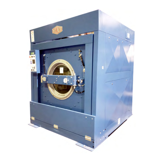
Milnor MWF100C7 Installation And Service (116 pages)
Brand:
Milnor
| Category:
Laundry Appliance
| Size: 8.32 MB
Table of Contents
Table of Contents
3
Limited Standard Warranty
5
How to Get the Necessary Repair Components
6
Trademarks
7
Installation
9
Safety-Tilting Washer-Extractors
10
How to Use the Safety Stands on 48" Air-Tilting
16
Shipping Brackets
19
Guards and Covers
21
Mwf125C7,Y7
22
Safety Placards and Locations ISO - MWF100C7,Y7
29
Handling a Washer-Extractor from Delivery to Final Location
31
Prevent Damage from Chemical Supplies and Chemical Systems
37
Vital Information about the Forces Imparted to Supporting
41
Service and Maintenance
43
Connection Precautions for Washer-Extractors
44
Drive Assemblies
55
Drive Components
56
Cylinder & Bearing Installation
60
Air Injection Components
69
Suspension Assemblies
71
Suspension
72
Tilt Assemblies
75
Tilt Components
76
Door Assemblies
81
Manual Door
82
Door Latch Small
88
Water, Steam & Drain
89
Water and Steam Schematic and Components
90
Water Inlet Components and Installation
92
Steam
94
Drain Valve to Bottom
95
Chemical Supply Assemblies
97
Soap Chute
98
Peristaltic Chemical Inlets
100
Pneumatic Assemblies
103
Pneumatic Schematic
104
Control and Sensing Assemblies
107
Water Level & Temperature Sensor
108
Reference
109
Dimensional Drawings
111
Milnor MWF100C7 Installation And Service (110 pages)
Washer Extractors
Brand:
Milnor
| Category:
Washer
| Size: 6.94 MB
Table of Contents
Table of Contents
3
Limited Standard Warranty
5
How to Get the Necessary Repair Components
6
Trademarks
7
Safety-Suspended, Open Pocket, Non-Tilting Washer-Extractors
8
Installation
23
About the Forces Transmitted by Milnor® Washer-Extractors
24
Prevent Damage from Chemical Supplies and Chemical Systems
26
Shipping Brackets
34
Covers
36
Service and Maintenence
39
Service Connections
40
Servicing the Door to Open It with Power off or with a Malfunctioning Door Lock
45
Torque Requirements for Fasteners
53
Drive Assemblies Drive
61
Bearing Housing Components MWF27
64
Bearing Installation MWF27
68
69 4. Suspension
74
Marshmallow Suspension
74
Shocks
76
Shell and Door Assemblies
79
Door Assembly and Installation
80
Door Lock Mechanism
83
Door Handle and Lock Actuator
86
85 6. Water and Steam Piping and Assemblies
90
Water & Steam Components
90
93 7. Chemical Supply Devices
97
Soap Chute
98
Peristaltic Supply
100
Compartment Supply
103
Dimensional Drawings
107
Advertisement
Milnor MWF100C7 Manual (44 pages)
Brand:
Milnor
| Category:
Industrial Equipment
| Size: 5.4 MB
Table of Contents
Table of Contents
8
Machine Description and Identification
11
About this Manual and Your Milnor® Machine
11
Description
11
Machine Identification
11
Machine Data Plate
11
Figure 1 Machine Data Plate
11
Safety
12
Tilting Washer Extractors
12
Safety Alert Messages-Internal Electrical and Mechanical Hazards
12
Safety Alert Messages-Cylinder and Processing Hazards
13
Safety Alert Messages-Unsafe Conditions
14
Damage and Malfunction Hazards
14
Hazards Resulting from Inoperative Safety Devices
14
Hazards Resulting from Damaged Mechanical Devices
15
Careless Use Hazards
15
Careless Operation Hazards-Vital Information for Operator Personnel (See also Operator Hazards Throughout Manual)
15
Careless Servicing Hazards-Vital Information for Service Personnel (See also Service Hazards Throughout Manuals)
16
Prevent Damage from Chemical Supplies and Chemical Systems
17
How Chemical Supplies Can Cause Damage
17
Dangerous Chemical Supplies and Wash Formulas
17
Incorrect Configuration or Connection of Equipment
17
Figure 2 Incorrect Configurations that Let the Chemical Supply Go in the Ma
18
Equipment and Procedures that Can Prevent Damage
19
Use the Chemical Manifold Supplied
19
Figure 3 Incorrect Configurations that Let the Chemical Supply Go in the Ma
19
Figure 4 Examples of Manifolds for Chemical Tubes. Your Equipment Can Look
19
Close the Line
20
Do Not Let a Vacuum Occur
20
Flush the Chemical Tube with Water
20
Put the Chemical Tube Fully below the Inlet
20
Prevent Leaks
20
Use the Red Safety Supports for Maintenance - MWF_C_, MWF_Y
20
What Safety Supports Are Provided and Why
20
Figure 5 a Configuration that Prevents Flow in the Machine When the Pump Is off (if the Chemical Tube and Tank Have no Pressure)
20
How to Deploy the Safety Stands
21
Routine Maintenance
22
Maintenance Summary
22
Guards and Related Components
23
Filters, Screens, and Sensitive Components
23
Table 1 Guards and Related Components
23
Table 2 Filters, Screens, and Sensitive Components
23
Fluid Containers
24
Components that Become Worn
24
Bearings and Bushings
24
Table 3 Fluid Containers
24
Table 4 Components that Become Worn
24
Motor Grease Schedule
25
Mechanisms and Settings
25
Table 5 Bearings and Bushings
25
Table 6 Motor Grease Schedule
25
Table 7 Mechanisms and Settings
25
How to Remove Contamination
26
Table 8 Contamination Types, Cleaning Agents, and Procedures
26
Lubricant Identification
27
Table 9 Lubricant Identification
27
Grease Gun Procedures
28
Procedures for Bearing Components Connected to a Grease Plate
28
Procedures for Motors
29
Figure 6 Motor Grease Maintenance Conditions
30
How to Show the Maintenance on a Calendar
31
Table 10 Motor Grease Intervals and Quantities
31
Maintenance Components-Machines and Controls Group
32
How to Examine V-Belts and Pulleys
32
Figure 7 Belt and Pulley Conditions to Look for
32
Table 11 Where to Put Marks on a Calendar
32
Figure 8 How to Adjust Belt Tension on a Machine that Uses Spring Tension
33
Inverters
34
Chemical Devices
34
Figure 9 Electric Box and Inverter. These Are Examples. Your Machine Can Look
34
Water and Steam Devices
35
Figure 10 Chemical Inlet Manifolds for Chemical Pump Systems. See Caution
35
Figure 11 Soap Chute and Optional 5-Compartment Supply Injector. These Are Ex
35
How to Examine Compressed Air Mechanisms
36
Figure 12 Water Pressure Regulator for Chemical Flush. These Are Examples
36
Figure 13 Steam Inlet Strainer. These Are Examples. Your Machine Can Look Different
36
Figure 14 Compressed Air Inlet Strainers. These Are Examples. Your Machine Can Look Different
37
Figure 15. Self-Purging Air Line Filter to Remove Moisture and Other Contamination. These Are Examples. Your Machine Can Look Different
37
Figure 16 Compressed Air Mechanisms These Are Examples. Your Machine Can Look Different
38
Photoeyes and Proximity Switches
39
How to Do a Test of Emergency Stop Mechanisms
39
Figure 17 Speed Sensor (Photoeye) on some Machines
39
Proximity Switches These Are Examples. Your Machine Can Look Different
39
Maintenance Components-Large Extractors
41
Lubricant Maintenance for Grease-Filled Drive Bearings
41
Lubricant Maintenance for Non-Drive Components
41
Grease Ports for Grease-Only Bearing Assembly
41
Grease Ports for Door-Open Pocket Models. These Are Examples
41
How to Do a Test of the Mechanical Brake
42
About the Shock Absorbers
43
Advertisement
Related Products
Milnor MWF100J7
Milnor MWF100Y7
Milnor MWF100Z7
Milnor MWF18Z8
Milnor MWF18J8
Milnor MWF77C7
Milnor MWF45J8
Milnor MWF C Series
Milnor MWF63Y Series
Milnor MWF77Y Series
Milnor Categories
Washer
Industrial Equipment
Controller
Laundry Appliance
Dryer
More Milnor Manuals
Login
Sign In
OR
Sign in with Facebook
Sign in with Google
Upload manual
Upload from disk
Upload from URL