Sign In
Upload
Manuals
Brands
Milnor Manuals
Washer
48040F7D
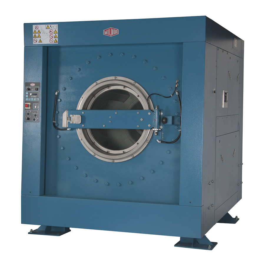
Milnor 48040F7D Manuals
Manuals and User Guides for Milnor 48040F7D. We have
5
Milnor 48040F7D manuals available for free PDF download: Operator's Manual, Installation And Service, Safety Manual, Manual
Milnor 48040F7D Operator's Manual (346 pages)
Brand:
Milnor
| Category:
Controller
| Size: 7.01 MB
Table of Contents
Table of Contents
126
Vidange Trop Longue
162
Circuit À 3 Fils Désactivé
162
Trop de Temps Avant Vapeur
162
Refroidissement Trop Long
163
Contrôler la Sonde de Température
163
Niveau en Cours
163
Panne de Communication Série
163
Défaillance du Capteur de Vitesse
164
Inverseur Déclenché
164
Erreur de Défaut Externe
164
Défaut de Pression de Frein
164
Défaut de Pression de Palier
164
Messages Spécifiques Aux Modèles Miltouch-EX
164
Patins de Frein Usés
164
Commande Côté Propreté
164
Contrôler Le Système D'équilibrage/Commutateur D'excursion
165
Messages Spécifiques Aux Modèles Miltouch-EX Chargement/Déchargement Automatique Patins de Frein Usés
165
Chargement Abandonné
165
Déchargement Abandonné
165
4.2. Entrées Et Sorties Pour L'appareil de Contrôle Miltouch
165
Sorties
167
Miltouch 3 (WUMTGUIA 3.X)
167
Miltouch 2 (WUMTGUIA 2.X)
168
Détection des Balourds Et Équilibrage des Laveuses-Essoreuses (Document BICLUF02)
173
Modèles Miltouch
173
Modèles Miltouch-EX ® Différents du 72046M5K
174
Si L'opération Suivante Est un Essorage Intermédiaire
174
Si L'opération Suivante Est un Essorage Final
174
Si Le Commutateur D'excursion Est Déclenché
175
Si Le Commutateur D'excursion Ne Se Déclenche Pas
175
Modèle Miltouch-EX ® 72046M5K
175
Si L'opération Suivante Est un Essorage Intermédiaire
175
Si L'opération Suivante Est un Essorage Final
175
Si Le Commutateur D'excursion Ne Se Déclenche Pas
176
4.5. Système de Détection Déséquilibré
176
Exigences
176
Test
177
Advertisement
Milnor 48040F7D Operator's Manual (110 pages)
MilTouch Controller
Brand:
Milnor
| Category:
Controller
| Size: 7.18 MB
Table of Contents
English
9
Table of Contents
9
Chapter 1. How to Use the Miltouch ™ Control
13
Using the Miltouch Control
13
The Home Display
13
The Wash Formula Maintenance Display
14
To Change an Existing Wash Formula
15
To Add a New Wash Formula
16
The Configuration Display
17
The Machine Configure Decisions
17
To Erase a Wash Formula
17
The Data Transfer Display
19
The Default Formulas by Laundry Type
19
Controller
21
Data Transfer with the Miltouch Programmer Software
21
How to Mount a USB Flash Drive to the Machine
21
How to Save and Transfer Wash Formulas
21
How to Save Machine Configuration Files
21
How to Transfer Machine Configuration Files to a Miltouch Machine
21
The Data Log Displays
22
The Date Selection Display
22
The Production Display
22
The Configuration and Programming Display
23
The Errors Display
23
The Inputs and Outputs Displays
24
The Run Display
26
The Names and Timers on the Run Display
26
The Machine Status Data
27
Chapter 2. How to Update the Machine Software
29
Miltouch Update: WUMTGUI/2.1
29
Does My Machine Need this Update
29
How Do I Save My Formulas and Machine Configuration
30
How Do I Update the Machine Software
31
Chapter 3. Miltouch ™ Wash Formulas
33
Miltouch Formula Decisions (Document BICLJP02)
33
Type = Type of Step
33
Time = Step Duration
33
Temp = Commanded Bath Temperature (Optional)
33
Hot = Hot Water Valve
33
Cold = Cold Water Valve
34
Third Water Valve (Optional)
34
Level = Bath Level
34
Steam (Optional)
34
C = Chemicals
34
W = When to Inject Chemicals
35
Chemical Dose = Chemical Injection Duration
35
Wash Speed
35
How to End Formula
36
Chapter 4. Troubleshooting
41
Door Opened
41
Vibration Switch Tripped
41
Too Long to Fill
41
Too Long to Drain
42
3-Wire Circuit Disabled
42
Too Long to Steam
42
Too Long to Cool
43
Check Temperature Probe(S)
43
Level Made after Drain
43
Serial Communication Failure
43
Failed Speed Sensor
43
Inverter Tripped
44
External Fault Error
44
Brake Pressure Fault
44
Bearing Pressure Fault
44
Check Flow Meter
44
Tank Pump Ol Tripped
44
Recirc Pump Ol Tripped
44
Loading Aborted
45
Discharge Aborted
45
Invalid Formula
45
Load Eye Blocked
45
Up Lock Not Made
45
Invalid Work Order
45
Invalid Goods Code
45
Invalid Customer Code
45
Can't Find Data
45
Accumulator was Reset
45
Outputs
47
Miltouch 2 (WUMTGUIA 2.X)
48
Inputs
50
Components of the Miltouch ™ Controller Circuit Boards
50
Processor Board (P/N: 08BHPAR91_)
51
Input/Output Board (P/N: 08BHF120A_)
52
4.4. Out-Of-Balance Detection System
53
Requirements
53
Testing
54
Deutsch
61
Abschnitte
62
Kapitel 1. Verwendung der Steuerung Miltouch
66
Verwenden der Miltouch ™ -Steuerung
66
Die Home Anzeige
66
Die Wash Formula Maintenance Anzeige
67
So Ändern Sie eine Bestehende Waschformel
68
Zum Hinzufügen einer Neuen Waschformel
70
Zum Löschen einer Waschformel
70
Die Konfigurations-Azeige
71
Die Maschinenkonfigurations-Entscheidungen
71
Die Standardformeln nach Wäschereityp
73
Die Data Transfer Anzeige
74
Datentransfer mit der Miltouch Programmier-Software
75
So Speichern Sie Dateien mit Maschinenkonfigurationen
75
Wie ein USB-Flashdrive an die Maschinensteuerung Angeschlossen wird
75
Die Datenauswahl-Anzeige
76
So werden Waschformeln Gespeichert und Übertragen
76
So Übertragen Sie Maschinenkonfigurationsdaten auf eine Miltouch Maschine
76
Die Anzeige Konfiguration und Programmierung
77
Die Produktions-Anzeige
77
Die Fehler-Anzeige
78
Die Anzeige Inputs and Outputs
78
Die Betrieb Anzeige (Dokument BICLJO01)
80
Die Bezeichnungen und Timer auf der Betrieb Anzeige
81
Die Maschinenstatus-Daten
81
Die Betriebszustände der Maschine
82
Die Standard- und Popup-Steuerelemente in der Betriebsanzeige
82
Aktualisierung Miltouch: WUMTGUI/2.1
84
Braucht meine Maschine diese Aktualisierung
84
Wie kann ich meine Formeln und Maschinenkonfigurationen Speichern
85
Wie Aktualisiere ich die Maschinensoftware
87
Wie kann ich meine Formeln und Konfigurationen wieder Herstellen
87
Kapitel 2. Wie wird die Maschinensoftware Aktualisiert
84
Entscheidungen Miltouch-Formeln (Dokument BICLJP02)
88
Type = Typ des Schrittes
88
Time = Schrittdauer
88
Hot = Heißwasserventil
88
Cold = Kaltwasserventil
89
Drittwasser-Ventil (Option)
89
Level = Laugen-Füllhöhe
89
Dampf (Optional)
89
W = Wann die Chemikalie Eingespritzt wird
90
Chemical Dose = Einspritzdauer der Chemikalie
90
Signal bei Chemikalien-Einspritzung
90
Wash Speed
90
Art des Entleerens
90
Re-Use Drain (Optional)
91
Beenden einer Formel
91
Kapitel 3. Miltouch ™ Waschformeln
88
Rinsave ™ Formeln für Gewerbliche Wäschereien
91
Kapitel 4. Fehlersuche
96
Miltouch ™ und Miltouch-EX ™ Fehlermeldungen
96
Tür Offen
96
Schwingungsschalter Ausgelöst
96
Zu Lang für Ablassen
97
3-Anschlüsse Ausgeschaltet
97
Zu Lang für Dampf
97
Zu Lang zu Abkühlen
98
Temperaturfühler Überprüfen
98
Wasser in der Maschine nach dem Ablassen
98
Fehler Serielle Kommunikation
98
Geschwindigkeitssensor Versagt
98
Frequenzumwandler Ausgelöst
99
Externer Fehler
99
Fehler Bremsdruck
99
Fehler Lagerdruck
99
Durchflussmesser Überprüfen
99
ÜL Tankpumpe Ausgelöst
99
ÜL Umlaufpumpe Ausgelöst
99
Beladung Abgebrochen
100
Entladen Abgebrochen
100
Ungültige Formel
100
Fotozelle Beladung Blockiert
100
Sperre Oben nicht Eingerastet
100
Ungültiger Arbeitsauftrag
100
Ungültiger Wäschestück-Code
100
Ungültiger Kunden-Code
100
Ungültiger Angestellten-Code
100
Daten können nicht Gefunden werden
100
Ausgänge
102
Miltouch 3 (WUMTGUIA 3.X)
102
Miltouch 2 (WUMTGUIA 2.X)
103
Eingänge
104
Komponenten der Miltouch ™ Controller-Leiterplatte
105
Prozessorkarte (Teilenr.: 08BHPAR91_)
105
Eingangs-/Ausgangskarte (Teilenr.: 08BHF120A_)
106
Unwucht-Erkennungssystem (Dokument BICLUT04)
107
Anforderungen
107
Milnor 48040F7D Safety Manual (79 pages)
Tilting Washer-extractor
Brand:
Milnor
| Category:
Washer
| Size: 0.99 MB
Table of Contents
English
8
Table of Contents
8
1 For Owner/Management
10
Vital Safety Information for Owner/Management
10
Preservation of Safe Product Design
10
Safety in Laundry Design
10
Fostering a Safe Laundry Facility
11
Proximity Safeguarding for Automatic Shuttle Conveyors
12
Applicability
12
References for Proximity Safeguarding
13
Hazards to Personnel in Proximity to Shuttle Conveyors
13
How Milnor Accommodates Proximity Safeguarding
14
Examples of Safety Fencing with Interlocked Gates
14
Figure
14
Figure 1 Example Fence Layout for Automated Laundering System Where One
15
Figure 2 Example Fence Layout for Automated Laundering System Where Two
15
Fence Dimensions
16
Fence Materials and Setback
16
Gates
16
Control Circuitry
16
System Emergency Stop Switches
16
Isolating Individual Machine Controls
16
Recommended Signage
17
Wiring Safety Fence Gate Interlocks on Milnor Shuttles, Presses and Centrifugal Extractors
17
Precautions
17
Wiring Guidelines
17
Testing
18
Testing Gate Interlocks
18
Testing Three-Wire Circuit Components on each Interlocked Machine
18
Table 1 Typical Three-Wire Circuit Components
19
2 For All Users
20
Internal Electrical and Mechanical Hazards
20
Safety Placards-Internal Electrical and Mechanical Hazards
20
Safety Alert Messages-Internal Electrical and Mechanical Hazards
20
External Mechanical Hazards
21
Safety Placards-External Mechanical Hazards
21
Figure 4 External Mechanical Hazards
21
Safety Alert Messages-External Mechanical Hazards
22
Cylinder and Processing Hazards
22
Safety Placards-Cylinder and Processing Hazards
22
Safety Alert Messages-Cylinder and Processing Hazards
23
Figure 5 Cylinder and Processing Hazards
23
Safety Alert Messages-Unsafe Conditions
24
Damage and Malfunction Hazards
24
Hazards Resulting from Inoperative Safety Devices
24
Hazards Resulting from Damaged Mechanical Devices
25
Careless Use Hazards
26
Careless Operation Hazards-Vital Information for Operator Personnel (See also Operator Hazards Throughout Manual)
26
Careless Servicing Hazards-Vital Information for Service Personnel (See also Service Hazards Throughout Manuals)
26
Español
32
Contenido
33
1 Para el Propietario/Administrador
34
Información Esencial de Seguridad para el Propietario/Administrador
34
Conservación del Diseño de Productos Seguros
34
Seguridad en el Diseño de la Lavandería
34
Propiciación de unas Instalaciones de Lavandería Seguras
35
Protección de Proximidad para Cintas Transportadoras Automáticas
37
Aplicabilidad
37
Referencias para Protección de Proximidad
37
Peligros para el Personal en Proximidad a Cintas Transportadoras
37
Cómo Incorpora Milnor la Protección de Proximidad
38
Ejemplos de Barreras de Seguridad con Puertas Enclavadas
39
Dimensiones de la Barrera
41
Materiales y Retroceso de la Barrera
41
Puertas
41
Circuitos de Control
41
Interruptores de Parada de Emergencia del Sistema
41
Aislamiento de Controles de Máquina Individuales
42
Señalización Recomendada
42
Enclavamiento de la Puerta de la Barrera de Seguridad para el Cableado en Cintas
42
Precauciones
42
Pautas de Cableado
43
Prueba
43
Prueba de Enclavamientos de Puerta
44
Prueba de Componentes del Circuito Trifásico en cada Máquina con Enclavamiento
44
2 Para todos Los Usuarios
45
Riesgos Electromecánicos Internos
45
Placas de Seguridad: Riesgos Electromecánicos Internos
45
Mensajes de Alerta de Seguridad: Riesgos Electromecánicos Internos
45
Riesgos Mecánicos Externos
46
Placas de Seguridad: Riesgos Mecánicos Externos
46
Mensajes de Alerta de Seguridad: Riesgos Mecánicos Externos
47
Riesgos del Tambor y el Procesamiento
48
Placas de Seguridad: Riesgos del Tambor y el Procesamiento
48
Mensajes de Alerta de Seguridad: Riesgos del Tambor y el Procesamiento
48
Mensajes de Alerta de Seguridad: Condiciones no Seguras
50
Riesgos por el Deterioro y el Funcionamiento Incorrecto
50
Riesgos Causados por Dispositivos de Seguridad Inoperantes
50
Riesgos Causados por Dispositivos Mecánicos Deteriorados
51
Riesgos de Los Descuidos en el Uso
52
Riesgos de Los Descuidos en el Manejo: Información Vital para Los Operadores (Consulte También Los Riesgos para el Operador en todo el Manual)
52
Riesgos de Los Descuidos en el Mantenimiento y las Reparaciones: in
53
Deutsch
58
1 Für Eigentümer und Management
60
Wichtige Sicherheitsinformationen für den Eigentümer/Das Management
60
Wahrung eines Sicheren Produktdesigns
60
Sicherheitskonzept für Wäschereien
60
Schaffung eines Sicheren Wäschereibetriebs
61
Annäherungsschutz für Automatische Transportbänder
63
Anwendbarkeit
63
Referenzen zu Annäherungsschutz
63
Gefahren für Mitarbeiter in der Nähe von Transportsystem-Förderbändern
63
So Sieht Milnor den Annäherungsschutz vor
64
Beispiel für Umzäunungen mit Elektrisch Überwachten Türen
65
Maße der Umzäunung
67
Material und Abstand der Umzäunung
67
Türen
67
Steuerungsschaltung
67
System-Notstoppschalter
67
Abtrennen Einzelner Maschinensteuerungen
68
Empfohlene Beschilderung
68
Verdrahtung von Sicherheitstürschaltern an Transportsystemen, Pressen und Ent
68
Warnhinweise
68
Richtlinien zur Verdrahtung
69
Prüfen
69
Prüfen der Türschalter
70
Prüfen der Dreileiterschaltungskomponenten der Einzelnen Gesicherten Maschinen
70
2 Für alle Benutzer
71
Interne Elektrische und Mechanische Gefahren
71
Sicherheitsschilder - Interne Elektrische und Mechanische Gefahren
71
Sicherheitswarnmeldungen - Interne Elektrische und Mechanische Gefahren
71
Externe Mechanische Gefahren
72
Sicherheitsschilder - Externe Mechanische Gefahren
72
Sicherheitswarnmeldungen - Externe Mechanische Gefahren
73
Gefahren Bezüglich Trommel und Verarbeitung
74
Sicherheitsschilder - Gefahren Bezüglich Trommel und Verarbeitung
74
Sicherheitswarnmeldungen - Gefahren Bezüglich Trommel und Verarbeitung
74
Sicherheitswarnmeldungen - Unsichere Bedingungen
76
Gefahren durch Schäden und Störungen
76
Gefahren Aufgrund von Defekten Sicherheitsvorrichtungen
76
Gefahren Aufgrund von Beschädigten Mechanischen Vorrichtungen
77
Gefahren durch Nachlässige Behandlung
78
Advertisement
Milnor 48040F7D Installation And Service (135 pages)
Brand:
Milnor
| Category:
Washer
| Size: 15.18 MB
Table of Contents
Table of Contents
3
Service and Maintenance
3
Limited Standard Warranty
5
How to Get the Necessary Repair Components
6
Trademarks
7
Installation
9
Safety-Tilting Washer-Extractors
10
Safety Supports: 48040F_ Air-Tilt Washer-Extractors
16
How to Use the Safety Stands on 48" Air-Tilting
22
Panels and Covers
23
Safety Placards and Locations-ISO-48040F7J, 48040F7W
25
48040F7J(Az), 48040F7Z (Az)
25
Safety Placards and Locations-ISO-48040F7B, 48040F7N
27
48040F7B (Az), 48040F7D (Az)
27
Foot Guard Assembly
29
48040F_, 48040H_, & 68036H_ Washer Extractor
30
Prevent Damage from Chemical Supplies and Chemical Systems
35
About the Forces Transmitted by Milnor
40
Washer-Extractors
40
How Strong and Rigid
40
Service and Maintenance
43
Service Connections
44
Torque Requirements for Fasteners
47
Drive Assemblies
67
Drive Components and Belt Installation
68
Cylinder and Bearing Installation MWF100, 4840F
71
Bearing Assembly MWF100, 4840F
74
Air Injection Components
80
Brake Components
82
Air Cylinder Components and Installation
85
Suspension
87
Suspension Components
88
Tilt Assemblies
91
Air Tilt
92
Door Assemblies
95
Manual Door
96
Door Latch
101
Water, Steam & Drain
103
Water and Steam Schematics and Components
104
Water Inlet Components and Installation
106
Water Inlet Components for Tilt Washers
109
Steam Inlet Components and Installation
112
Drain Valve Body with One Valve
114
Drain Valve Body with Two Valves
115
Chemical Supply Assemblies
117
Soap Chute
118
Peristaltic Chemical Inlets
120
Pneumatic Assemblies
123
Reference
127
Dimensional Drawings
129
Milnor 48040F7D Manual (45 pages)
Brand:
Milnor
| Category:
Industrial Equipment
| Size: 5.5 MB
Table of Contents
Table of Contents
8
Machine Description and Identification
11
About this Manual and Your Milnor® Machine
11
Description
11
Machine Identification
11
Machine Data Plate
11
Figure 1 Machine Data Plate
11
Safety
12
Tilting Washer Extractors
12
Safety Alert Messages-Internal Electrical and Mechanical Hazards
12
Safety Alert Messages-Cylinder and Processing Hazards
13
Safety Alert Messages-Unsafe Conditions
14
Damage and Malfunction Hazards
14
Hazards Resulting from Inoperative Safety Devices
14
Hazards Resulting from Damaged Mechanical Devices
15
Careless Use Hazards
15
Careless Operation Hazards-Vital Information for Operator Personnel (See also Operator Hazards Throughout Manual)
15
Careless Servicing Hazards-Vital Information for Service Personnel (See also Service Hazards Throughout Manuals)
16
Use the Red Safety Supports for Maintenance - 48040F7B, 48040F7D
17
What Safety Supports Are Provided and Why
17
How to Deploy the Safety Stands
17
Prevent Damage from Chemical Supplies and Chemical Systems
18
How Chemical Supplies Can Cause Damage
18
Dangerous Chemical Supplies and Wash Formulas
18
Incorrect Configuration or Connection of Equipment
18
Figure 2 Incorrect Configurations that Let the Chemical Supply Go in the Ma
19
Equipment and Procedures that Can Prevent Damage
20
Use the Chemical Manifold Supplied
20
Figure 3 Incorrect Configurations that Let the Chemical Supply Go in the Ma
20
Figure 4 Examples of Manifolds for Chemical Tubes. Your Equipment Can Look
20
Close the Line
21
Do Not Let a Vacuum Occur
21
Flush the Chemical Tube with Water
21
Put the Chemical Tube Fully below the Inlet
21
Prevent Leaks
21
Figure 5 a Configuration that Prevents Flow in the Machine When the Pump Is off (if the Chemical Tube and Tank Have no Pressure)
21
Routine Maintenance
22
Maintenance Summary
22
Guards and Related Components
23
Filters, Screens, and Sensitive Components
23
Table 1 Guards and Related Components
23
Table 2 Filters, Screens, and Sensitive Components
23
Fluid Containers
24
Components that Become Worn
24
Table 3 Fluid Containers
24
Table 4 Components that Become Worn
24
Bearings and Bushings
25
Motor Grease Schedule
25
Mechanisms and Settings
25
Table 5 Bearings and Bushings
25
Table 6 Motor Grease Schedule
25
How to Remove Contamination
26
Table 7 Mechanisms and Settings
26
Table 8 Contamination Types, Cleaning Agents, and Procedures
26
Lubricant Identification
27
Table 9 Lubricant Identification
27
Grease Gun Procedures
28
Procedures for Bearing Components Connected to a Grease Plate
28
Procedures for Motors
29
Figure 6 Motor Grease Maintenance Conditions
30
How to Show the Maintenance on a Calendar
31
Table 10 Motor Grease Intervals and Quantities
31
Maintenance Components-Machines and Controls Group
32
How to Examine V-Belts and Pulleys
32
Figure 7 Belt and Pulley Conditions to Look for
32
Table 11 Where to Put Marks on a Calendar
32
Figure 8 How to Adjust Belt Tension on a Machine that Uses Spring Tension
33
Inverters
34
Chemical Devices
34
Figure 9 Electric Box and Inverter. These Are Examples. Your Machine Can Look
34
Water and Steam Devices
35
Figure 10 Chemical Inlet Manifolds for Chemical Pump Systems. See Caution
35
Figure 11 Soap Chute and Optional 5-Compartment Supply Injector. These Are Ex
35
Figure 12 Air Tube for the Water Level Sensor. These Are Examples. Your Ma- Chine Can Look Different
36
Figure 13 Water Pressure Regulator for Chemical Flush. These Are Examples
36
How to Examine Compressed Air Mechanisms
37
Figure 14 Steam Inlet Strainer. These Are Examples. Your Machine Can Look Different
37
Figure 15 Compressed Air Inlet Strainers. These Are Examples. Your Machine Can Look Different
37
Figure 16. Self-Purging Air Line Filter to Remove Moisture and Other Contamination. These Are Examples. Your Machine Can Look Different
38
Figure 17 Compressed Air Mechanisms These Are Examples. Your Machine Can Look Different
39
Photoeyes and Proximity Switches
40
How to Do a Test of Emergency Stop Mechanisms
40
Speed Sensor (Photoeye) on some Machines
40
Proximity Switches These Are Examples. Your Machine Can Look Different
40
Maintenance Components-Large Extractors
42
Lubricant Maintenance for Grease-Filled Drive Bearings
42
Lubricant Maintenance for Non-Drive Components
42
Grease Ports for Grease-Only Bearing Assembly
42
Grease Ports for Door-Open Pocket Models. These Are Examples
42
How to Do a Test of the Mechanical Brake
43
About the Shock Absorbers
44
Advertisement
Related Products
Milnor 48040F7B
Milnor 48040F7J
Milnor 48040F7Z
Milnor 48040F7N
Milnor 48040F7W
Milnor 48040F Series
Milnor 48040F7 Series
Milnor 48040H7W
Milnor 48040H7R
Milnor 48040M7K
Milnor Categories
Washer
Industrial Equipment
Controller
Laundry Appliance
Dryer
More Milnor Manuals
Login
Sign In
OR
Sign in with Facebook
Sign in with Google
Upload manual
Upload from disk
Upload from URL