Sign In
Upload
Manuals
Brands
Intel Manuals
Server
R1000WT Series
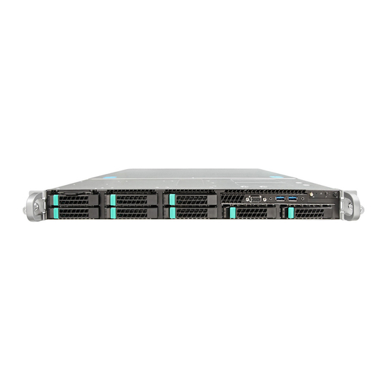
Intel R1000WT Series Manuals
Manuals and User Guides for Intel R1000WT Series. We have
2
Intel R1000WT Series manuals available for free PDF download: System Installation And Service, Configuration Manual
Intel R1000WT Series System Installation And Service (112 pages)
Brand:
Intel
| Category:
Server
| Size: 7.86 MB
Table of Contents
Document Revision History
2
Safety Information
4
About this Document
6
Document Organization
6
System Service
6
Additional Information and Software
7
Table of Contents
8
1 Server Building Block System Integration
15
Intel Server Chassis Identification
17
Prepare Chassis for Assembly
17
Figure 1. Intel® Server Chassis R1304Wtxxx - 4 X 3.5" Front Drive Bay
17
Figure 2. Intel® Server Chassis R1208WTXXX - 8 X 2.5" Front Drive Bay
17
Figure 3. Removing the System Cover
17
Figure 4. Chassis Components
18
Figure 5. System Fan Assembly Removal
19
System Assembly
20
Figure 6. Server Board Installation
20
Figure 7. SAS/SATA I/O Cable
21
Figure 8. Backplane Power Cable and SAS/SATA Data Cable Attachments
21
Figure 9. On-Board Mini-SAS HD Connectors for Embedded SATA Support
22
Figure 10. Hot Swap Backplane Power Cable
22
Figure 11. Hot Swap Backplane Power Cable Installation
22
Figure 12. System Fan Assembly Installation
23
Figure 13. Connect System Fan Cables
23
Figure 14. Hot Swap Backplane I
24
Figure 15. Backplane I2C Connector Location
24
Figure 16. Hot Swap Backplane I 2 C Internal Cable Connection
24
Figure 17. Front Control Panel and Front I/O Internal Cable Connections
25
Figure 18. Air Duct Side Wall and Support Bracket Installation
26
Figure 19. Power Supply and Power Supply Bay Filler Installation
28
2 Essential System Component Installation and Service
29
Internal Cable Routing
30
Figure 20. Internal Cable Routing
30
System Cover Removal / Installation
31
System Cover Removal
31
System Cover Installation
31
Figure 21. System Cover Removal
31
Figure 22. System Cover Installation
31
Air Duct Removal / Installation
32
Air Duct Removal
32
Air Duct Installation
32
Processor Installation / Removal
32
Figure 23. Air Duct Removal
32
Figure 24. Air Duct Installation
32
Figure 25. Processor Heatsink Removal
33
Processor Heatsink(S) Removal
33
Figure 26. Processor Installation - Open the Socket Lever
34
Figure 27. Processor Installation- Open the Load Plate
34
Processor Installation
34
Figure 28. Processor Installation - Install the Processor
35
Figure 29. Processor Installation - Remove the Socket Cover
35
Figure 30. Processor Installation - Close the Load Plate
36
Figure 31. Processor Installation - Latch the Locking Lever
36
Figure 32. Processor Heatsink Installation
37
Processor Heatsink Installation
37
Removing the Processor
37
Memory Installation and Removal
38
Memory Slot Population Requirements
38
DDR4 DIMM Installation
38
Figure 33. DIMM Blank
38
Figure 34. DDR4 DIMM Installation
38
Removing Memory
39
Figure 35. DDR4 DIMM Removal
39
Storage Device Installation / Removal
40
X 3.5" Front Drive Bay Storage
40
Figure 36. Installing Hot-Swap Storage Devices - 3.5" Carrier Extraction
40
Figure 37. 3.5" Drive Installation - Remove the Drive Blank
40
Figure 38. 3.5" Drive Installation - Mounting Drive to Carrier
41
Figure 39. Option to Install 2.5" SSD into a 3.5" Carrier
41
X 2.5" Front Drive Bay Storage
42
Figure 40. Drive Installation - Inserting 3.5" HDD Assembly
42
Figure 41. Installing Hot-Swap Storage Devices - 2.5" Carrier Extraction
42
Figure 42. 2.5" Storage Device Installation - Remove the Drive Blank
42
Riser Card Assembly - Removal / Integration / Installation
43
Figure 43. 2.5" Storage Device Installation - Mount Drive to Carrier
43
Figure 44. 2.5" Storage Device Installation - Inserting 2.5" Drive Assembly
43
Figure 45. PCI Riser Assembly Removal
44
Figure 46. Riser Card Installation to Riser Bracket
44
Mounting a Riser Card to the Riser Bracket
44
Riser Card Assembly Removal
44
Figure 47. PCI Add-In Card Installation
45
Figure 48. Installing PCI Riser Assembly
45
PCI Add-In Card Installation
45
PCI Riser Assembly Installation
45
Rack Handles - Installation / Removal
46
Installing the Rack Handles
46
Removing the Rack Handles
46
Figure 49. Installing the Rack Handle
46
Figure 50. Removing the Rack Handle
46
3 Option and Accessory Kit Integration and Service
47
Slimline Optical Drive - Installation and Removal
48
Slimline Optical Drive Installation
48
Figure 51. Installing the Plastic Mounting Clip to an Optical Drive
48
Figure 52. Peripheral Device Power Cable
48
Figure 53. Peripheral Power Connector on the Server Board
48
Figure 54. SATA 4/5 Port on the Server Board
49
Figure 55. Optical Drive Installation
49
Slimline Optical Drive Removal
50
Figure 56. Removing the Slimline Optical Drive
50
Power Supply Module - Installation / Removal
51
Power Supply Module Installation
51
Power Supply Module Removal
51
Figure 57. Power Supply Module Installation
51
Figure 58. Power Supply Module Removal
51
Power Cord Retention Strap Installation
52
Figure 59. Power Cord Retention Strap Installation
52
Intel® SAS RAID Module Installation / Removal
53
Intel® SAS RAID Module Installation
53
Intel® SAS RAID Module Removal
53
Figure 60. Intel® SAS RAID Module Installation
53
I/O Expansion Module - Installation / Removal
54
Intel® I/O Expansion Module Installation
54
Intel® I/O Expansion Module Removal
54
Figure 61. Installing Intel
54
Figure 62. Removing an I/O Expansion Module
54
SATA RAID 5 Upgrade Key - Installation / Removal
55
Installing the SATA RAID 5 Upgrade Key
55
Removing the SATA RAID 5 Upgrade Key
55
Figure 63. Installing the SATA RAID 5 Upgrade Key
55
Intel Remote Management Module 4 Lite Key - Installation / Removal
56
RMM4 Lite Key Installation
56
Intel RMM4 Lite Key Removal
56
Figure 64. Installing the Intel RMM4 Lite
56
Trusted Platform Module (TPM) Installation
57
Figure 65. Trusted Platform Module (TPM) Installation
57
Front Bezel - Installation / Removal
58
Bezel Snap-Ons
58
Figure 66. Installing the Snap-On to the Front Bezel
58
Figure 67. Removing the Snap-On from the Front Bezel
58
Front Bezel Installation
59
Front Bezel Removal
59
Figure 68. Installing the Front Bezel
59
Figure 69. Removing the Front Bezel
59
Intel RAID Maintenance Free Backup Unit (RMFBU) Installation/Removal
60
Intel RAID Maintenance Free Backup Unit (RMFBU) Installation
60
Figure 70. Intel® RAID Maintenance Free Backup Unit (RMFBU) Installation
60
Intel RAID Maintenance Free Backup Unit (RMFBU) Removal
61
Figure 71. Intel® RAID Maintenance Free Backup Unit (RMFBU) Removal
61
Dual Intel
62
RAID Maintenance Free Backup Units (RMFBU) Installation/Removal
62
RAID Maintenance Free Backup Unit (RMFBU) Assembly Installation
62
Figure 72. Standard RMFBU Mounting Plate Removal
62
Figure 73. AWTAUXBBUBKT 1U RMFBU Mounting Plate Installation
62
Figure 74. RMFBU Removal from Standard Housing
63
Figure 75. RMFBU Installation into Dual RMFBU Housing
63
Figure 76. Dual RMFBU Assembly Installation
63
Dual Intel
64
Figure 77. Dual RMFBU Assembly Removal
64
4 System Software Updates and Configuration
65
Updating the System Software Stack
65
Using the BIOS Setup Utility
65
Entering BIOS Setup
65
No Access to the BIOS Setup Utility
66
Navigating the BIOS Setup Utility
66
Table 3. BIOS Setup: Keyboard Command Bar
66
5 System Packaging Assembly
68
Accessory Kit
68
System Packaging Assembly Instructions
69
Figure 78. Package Assembly Reference Diagram
69
6 System Service - System Features Overview
74
System Feature Reference Diagrams
74
Front Drive Bay Options
74
Figure 80. 3.5" Drive Bay - 4 Drive Configuration - Intel® Server System R1304Wtxxxx
74
Figure 81. 2.5" Drive Bay - 8 Drive Configuration - Intel® Server System R1208Wtxxxx
74
Control Panel Features
75
Front I/O Features
75
Back Panel Features
75
Figure 82. Control Panel Features
75
Figure 83. Front I/O Panel Features
75
Figure 84. Back Panel Features
75
Server Board Features
76
Figure 85. Server Board Feature Identification
76
Figure 86. Intel Light-Guided Diagnostic Leds - Server Board
77
Figure 87. DIMM Fault Leds
78
Figure 88. System Fan Connections
78
System Configuration and Recovery Jumpers
79
BIOS Default Jumper Block
79
Serial Port 'A' Configuration Jumper
79
Figure 89. System Configuration and Recovery Jumpers
79
Password Clear Jumper Block
80
Management Engine (ME) Firmware Force Update Jumper Block
80
BMC Force Update Jumper Block
81
BIOS Recovery Jumper
81
7 System Service - FRU Replacement
83
System Fan Assembly Removal / Installation
84
System Fan Assembly Removal
84
System Fan Assembly Installation
84
Figure 90. System Fan Assembly Removal
84
Figure 91. System Fan Assembly Installation
84
Figure 92. Connect System Fan Cables
84
Replacing a System Fan
85
Figure 93. Remove a Failed System Fan
85
Replacing the System Battery
86
Figure 94. Replacing the Backup Battery
86
Replacing a Backplane
87
Removing the Backplane
87
Installing the Backplane
87
Figure 95. Removing the Backplane
87
Figure 96. Installing the Backplane
87
Replacing the Standard Front Control Panel
88
Standard Front Control Panel Removal
88
Standard Front Control Panel Installation
88
Figure 97. Standard Front Control Panel Removal
88
Figure 98. Standard Front Control Panel Installation
88
Replacing the Server Board
90
Server Board Removal
90
Figure 99. Server Board Removal
91
Server Board Installation
92
Appendix A: Getting Help
94
Appendix B: System Cable Routing Diagrams
95
Appendix C: System Status LED Operating States and Definition
97
Table 4. System Status LED State Definitions
97
Appendix D: POST Code Diagnostic LED Decoder Table
99
Figure 79. Intel
99
Figure 100. POST Diagnostic LED Location
99
Table 5. POST Progress Code LED Example
99
Table 6. MRC Progress Codes
100
Table 7. MRC Fatal Error Codes
101
Table 8. POST Progress Codes
102
Appendix E: POST Code Errors
105
Table 9. POST Error Codes and Messages
105
Table 10. POST Error Beep Codes
110
Table 11. Integrated BMC Beep Codes
111
Advertisement
Intel R1000WT Series Configuration Manual (104 pages)
Brand:
Intel
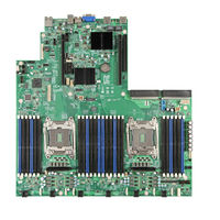
| Category:
Server Board
| Size: 4.75 MB
Table of Contents
Table of Contents
4
1 Intel Server Family Overview
9
Table 1. Product Family Reference Collaterals
10
Intel ® S2600Wt Product Family Naming Convention
11
Product Family Summary Chart
14
Table 2. Server Board Product Family Summary
14
Table 3. Server Chassis & Server System Product Family Summary
14
Intel ® S2600Gz/Gl Product
16
Guide
16
Table 4. 1U / 2U Server System Product Family Generation to Generation Transition Guide
16
2 Server Building Block Configuration
17
Building Block Recipe Summary
18
Table 5. 1U / 2U Building Block to Integrated System Recipe Guide
18
Intel® Server Board S2600WT Product Family Skus
19
Ipc - S2600WT2
19
Ipc - S2600WTT
19
Intel® Server Chassis R1000WT Product Family Skus - (1U Rack Mount Chassis)
20
R1304Wtxxx
21
R1208Wtxxx
22
Intel® Server Chassis R2000WT Product Family Skus - (2U Rack Mount Chassis)
23
R2312Wtxxx
24
R2000Wtxxx
25
3 Server System Configuration
26
Intel® Server System R1000WT Product Family Skus - (1U Rack Mount System)
27
R1304Wttgs
28
R1304Wt2Gs
29
R1208Wttgs
30
R1208Wt2Gs
31
Intel® Server System R2000WT Product Family Skus - (2U Rack Mount System)
32
R2208Wt2Ys
33
R2208Wttys
34
R2208Wttyc1
35
R2308Wttys
36
R2312Wttys
37
R2224Wttys
38
4 Sas / Sata Data Cable Guide
39
Sas / Sata Data Cable Connector Types
39
2U Server System Sas / Sata Cable Guide
40
X 3.5" - R1304Wtxxx SAS / SATA Data Cable Guide
42
X 2.5" - R1208Wtxxx SAS / SATA Data Cable Guide
43
X 3.5" - R2308Wtxxx Cable Guide
44
12 X 3.5 - R2312Wtxxx Cable Guide
45
Table 6. 2U 12 X 3.5" - R2312Wtxxx SAS / SATA Data Cable Guide (with SAS Expander)
47
2.5" Front Mount Drive Bay Cable Guide
49
Table 7. 2U 8 X 2.5" (Drive Bay #1) - SAS/SATA Data Cable Guid (with no SAS Expander)
50
Table 8. 2U 8 X 2.5" (Drive Bay #2) - SAS / SATA Data Cable Guide (with no SAS Expander)
51
Table 9. 2U 8 X 2.5" (Drive Bay #3) - SAS / SATA Data Cable Guide (with no SAS Expander)
52
Table 10. 2U 2.5" Front Mount Drive Configurations with SAS Expander - SAS Data Cable Guide
54
Intel Sas / Sata Data Cable Kits
56
Cable Kit
56
Table 11. Storage Data Cable Kit Description and Order Information
57
5 Intel 1U / 2U System Configuration Options
60
X 2.5" Combo Pci E * Sff (Nvm E ) Ssd / Sas Backplane - Intel ® Accessory Kit A1U44X25Nvmedk
60
8X2.5" - Intel® Accessory Kit A1U44X25NVMEDK Cable Guide
61
Sff
61
Table 12. 1U 8X2.5" Combo Backplane SAS/SATA Cable Guide
62
K It A2U44X25Nvmedk
63
8X2.5" - Intel® Accessory Kit A2U44X25NVMEDK SAS/SATA Cable Guide
65
16X2.5" / 24X2.5" -- Intel® Accessory Kit A2U44X25NVMEDK SAS / SATA Cable Guide
66
Rear Mount Hot Swap Drive Bay Accessory Kit - Ipc A2Urearhsdk
67
Ipc - A2UCBLSSD
67
Ipc A2U8X35S3Hsdk
68
2.5" Drive Bay Module Options
69
Ipc - A2U8X25S3HSDK
70
Ipc - A2U8X25S3DPDK
70
Ipc - A2UHANDLKIT
71
Locking Front Bezel Accessory Kits
72
Front Bezel Accessory Kit - Ipc A2UBEZEL
72
Front Bezel Accessory Kit - Ipc A1UBEZEL
73
2U Pcie* Riser Card Accessory/Spare FRU Options
74
Riser Card Options
74
Riser Card Options
75
Intel® I/O Expansion Modules
77
Intel Product Code
78
Ipc - AXX1P40FRTIOM
78
Ipc - AXX2P40FRTIOM
78
Ipc - AXX10GBNIAIOM
78
Ipc - AXX10GBTWLIOM3
79
Ipc - AXX1FDRIBIOM
79
Ipc - AXX2FDRIBIOM
79
Ipc - AXX4P1GBPWLIOM
80
Intel® SAS RAID Add-In Cards, Modules, and Accessories
81
Intel® Integrated RAID Module RMS3 Product Family - SAS 3.0 (12 Gb/S)
81
Intel® RAID Controller Add-In Cards - SAS 3.0 (12Gb/S)
83
Intel® RAID Accessory Options
86
Intel Power Supply Modules and Power Cords
89
2U Rack Mount Kits
90
Ipc - AXXPRAIL
90
Ipc - AXXELVRAIL
90
Ipc - AXX1U2UCMA
90
Ipc - AXX2POSTBRCKT
91
Intel® Xeon Phi™ Coprocessor Card and Non-Intel GPGPU Support
92
Ipc - AWTCOPRODUCT
93
Ipc - A2UL16RISER2
94
6 U / 2U Miscellaneous Accessory Options
95
Ipc - A1U2ULCP
95
Ipc - AXXSATADVDROM
95
Ipc - AXXSATADVDRWROM
95
Ipc - AXXSSDODDKIT
96
Ipc - AXXRJ45DB93
96
Ipc - AXXRMM4LITE
97
Ipc - AXXTPME5
97
7 U / 2U Spare and Replacement Parts (Frus)
98
8 Extended Warranty
102
Advertisement
Related Products
Intel R1000BB Family
Intel R1000RP Series
Intel R1000SP
Intel R1000GZ
Intel R1000GL
Intel R1000EP series
Intel R1000SPO series
Intel R1000WF Series
Intel R1000BB Series
Intel R1304BTLSHBN
Intel Categories
Motherboard
Computer Hardware
Server
Server Board
Desktop
More Intel Manuals
Login
Sign In
OR
Sign in with Facebook
Sign in with Google
Upload manual
Upload from disk
Upload from URL