Sign In
Upload
Manuals
Brands
Fluke Manuals
Thermal cameras
ThermoView TV46
Fluke ThermoView TV46 Manuals
Manuals and User Guides for Fluke ThermoView TV46. We have
2
Fluke ThermoView TV46 manuals available for free PDF download: User Manual
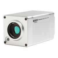
Fluke ThermoView TV46 User Manual (77 pages)
Thermal Imager Camera
Brand:
Fluke
| Category:
Thermal cameras
| Size: 3.66 MB
Table of Contents
Table of Contents
1
Table of Contents
3
List of Tables
4
List of Figures
5
Compliance Statement
8
Safety Information
9
Contacts
11
1 Description
12
Figure 1-1: Front and Rear View of Thermoview Series Infrared Cameras
12
Available Models
13
Figure 1-2: Available Models
13
System Architecture
14
Figure 1-3: System Architecture for Multiple Cameras and I/O Modules
14
2 Technical Data
15
Measurement Specification
15
Optical Specifications
16
Standard Lens
16
Electrical Specifications
17
PC Specifications
17
Environmental Specifications
17
Dimensions
18
Scope of Delivery
18
Figure 2-1: Dimensions of Thermoview TV40
18
3 Basics
19
Measurement of Infrared Temperature
19
Emissivity of Target Object
19
4 Environment
20
Ambient Temperature
20
Atmospheric Quality
20
Protection
20
Electrical Interference
20
5 Installation
21
Positioning
21
Distance to Object
21
Focusing
21
Mounting
21
Figure 5-1: Field of View for the Camera
21
Network
22
Cabling
22
Ethernet M12 Cable
22
Figure 5-2: Principal Cabling of Ethernet and Power Supply
22
Figure 5-3: Connecting the Ethernet M12 Cable to the Camera
23
Figure 5-4: Exemplary Ethernet M12 Cable
23
Power Supply Cable
24
Figure 5-5: Exemplary Power Supply Cable and Power Connector
24
6 Operation
25
Gige Vision Communication
25
LED Status Indicator
26
Figure 6-1: LED Status Indicator
26
Shutter
27
Web Server Application
28
Establishing Communication
28
Camera Info
28
Camera Access
28
Figure 6-2: Web Server Application
28
Network Configuration
29
Figure 6-3: Dialog Box for Uploading New Firmware
29
Figure 6-4: Dialog Box for the Network Configuration
29
Focus Control
30
Field of View
30
Temperature Unit
30
Emissivity
30
7 Accessories
31
Add-On Lenses
31
Wide Lens 0.75X
32
Figure 7-1: Dimensions of Thermoview TV40 with Wide Lens
32
Tele Lens 2X
33
Figure 7-2: Dimensions of Thermoview TV40 with Tele Lens 2X
33
Tele Lens 4X
34
Figure 7-3: Dimensions of Thermoview TV40 with Tele Lens 4X
34
Macro TV43
35
Macro TV46
35
Electrical Accessories
36
Ethernet Poe Cable (A-CB-XX-M12-W08-XX)
37
Table 7-1: Available Ethernet Poe Cables
37
Figure 7-4: Exemplary Ethernet Poe LT Cable
37
Power Supply Cable (A-CB-XX-PS-XX)
38
Table 7-2: Available Power Supply Cables
38
Figure 7-5: Exemplary Power Supply Cable
38
Ethernet Cable (A-CB-LT-RJ45-25)
39
Ethernet Cable Short (A-CB-LT-RJ45-03)
39
Figure 7-6: Ethernet Cable
39
Figure 7-7: Ethernet Cable Short
39
Fiber Optic Cable (A-CB-FO-XXX)
40
Poe Injector (A-TV-POE1)
41
Figure 7-8: Poe Injector for Office Environments
41
Poe Injector Industrial (A-TV-POE2)
42
Figure 7-9: Poe Injector for Industrial Environments
42
Figure 7-10: Dimensions
42
Power Supply DIN Rail (A-PS-DIN-24V)
44
Figure 7-11: Industrial Power Supply
44
Fiber Optic to Ethernet Converter (A-CON-FO-RJ45)
45
Figure 7-12: Fiber Optic to Ethernet Converter
45
Figure 7-13: Dimensions
45
Ethernet Switch (A-CON-SW)
47
Figure 7-14: Ethernet Switch
47
Figure 7-15: Dimensions
47
I/O Modules
49
Mechanical Accessories
50
Mounting Base (A-TV-MB)
51
Figure 7-16: Mounting Base
51
Air Purge Collar (A-TV-AP)
52
Figure 7-17: Air Purge Collar
52
Water Cooling Enclosure (A-TV-AP-WC)
54
Figure 7-18: Water Cooling Enclosure
54
Protective Enclosure (A-TV-WC)
56
Air Barrier
56
Figure 7-19: Protective Enclosure
56
Specification
57
Figure 7-20: Dimensions
57
Installation
58
Outdoor Enclosure (A-TV-ENC)
62
Specification
62
Figure 7-21: Outdoor Enclosure
62
Installation
63
Figure 7-22: Dimensions
63
Swivel Bracket (A-BR-S)
67
Figure 7-23: Swivel Bracket
67
Junction Box (A-TV-JB)
68
Figure 7-24: Junction Box
68
Protective Windows (A-TV-PW)
69
Figure 7-25: Protective Window
69
8 Maintenance
70
Fail-Safe Operation
70
Troubleshooting
70
Table 8-3: Troubleshooting
70
Cleaning the Lens
71
9 Appendix
72
Field of View Calculator
72
Figure 9-1: Field of View Calculator for the Camera
72
Avoidance of Condensation
73
Table 9-4: Minimum Device Temperatures [°C/°F]
73
Determination of Emissivity
74
Typical Emissivity Values
74
Advertisement
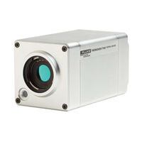
Fluke ThermoView TV46 User Manual (49 pages)
Thermal Imager Camera, ThermoView Series
Brand:
Fluke
| Category:
Thermal cameras
| Size: 1.71 MB
Table of Contents
Table of Contents
4
1 Safety Instructions
8
2 Product Description
10
Figure 1: Front and Rear View of Thermoview ® Series Infrared Cameras
10
System Architecture
11
Figure 2: Typical System Architecture for Multi Thermoview ® Camera Usage
11
Figure 3: Identification Matrix for Thermoview ® Infrared Cameras
11
3 Technical Data
12
General Specifications
12
Electrical Specifications
12
Measurement and Optical Specifications
13
Dimensions
13
Scope of Delivery
14
4 Basics to Keep in Mind
14
Thermoview ® TV40 Imager Location
14
Figure 5: Dimensions of Thermoview ® Imager with Add-On Lenses
14
Measurement of Infrared Temperatures
15
Emissivity of Target Object
15
5 Installation
15
Ambient Temperatures
15
Environment
15
Electrical Interference
15
Geometry
16
Spot Size (IFOV) Calculation of Aperture Angle for Different Lens Types
16
Figure 6: Field of View for the Camera
16
Figure 7: Picture Extract of the Thermoview® Field of View Calculator
16
Focusing
17
Mounting
17
Cable Connections
17
Connecting the Gige Vision Ethernet Communication Cable
17
Figure 8: Focusing the Thermoview® Camera Via PC Software (no Manual Focus)
17
Connecting the Power Supply Cable
18
Figure 9: Power Connector
18
Gige Vision Communication
19
Thermoview ® LED Status Indicator
19
Figure 10: Position of the Thermoview® Camera Status Indicator LED
19
6 Internal Thermoview Web-Server Application
20
Figure 11: Screenshot of the Thermoview® Onboard Web-Server Application
20
7 Accessories
21
Available Electrical Accessories for Thermoview ® Cameras
21
Power Supply Cable, 80°C Max., 7.5M (25Ft.), (A-CB-LT-PS-07)
21
Power Supply Cable, 80°C Max., 25M (80Ft.), (A-CB-LT-PS-25)
22
Power Supply Cable, 80°C Max., 50M (160Ft.), (A-CB-LT-PS-50)
22
Ethernet Cable, 80°C Max., 7.5M (25Ft.), (A-CB-LT-M12-W08-07)
22
Figure 12: Power Supply Cable 7.5M (25Ft.) with Related Plug-In Contact Assignment
22
Figure 13: Ethernet Cable 7.5M (25Ft.) with RJ45 and M12 Connector
22
Ethernet Cable, 80°C Max., 25M (80Ft.), (A-CB-LT-M12-W08-25)
23
Ethernet Cable, 80°C Max., 50M (160Ft.), (A-CB-LT-M12-W08-50)
23
Poe Injector (Standard), 115/230VAC, (A-TV-POE1)
23
Figure 14: Standard Poe Injektor to Conform to Office Environments
23
Poe Injector (Industrial), 115/230VAC, (A-TV-POE2)
24
Figure 15: Industrial Poe Injektor to Conform to Extended Temp. Environments
24
VDC 1.3 a Industrial Power Supply, DIN Rail Mount (A-PS-DIN-24V)
26
Ethernet Cable 25 M (82 Ft), Two RJ45 Connectors (A-CB-LT-RJ45-25)
26
Figure 16: 24 VDC, 1.3 a Industrial Power Supply (A-PS-DIN-24V)
26
Figure 17: Ethernet Cable 25 M (82 Ft) with RJ45 Connectors on both Ends
26
Fiber Optic to Ethernet Converter (A-CON-FO-RJ45)
27
Figure 18: Fiber Optic to Ethernet Converter (6 RJ45 & 2 Multi Mode FO Ports)
27
Fiber Optic Cable 150 M (492 Ft) (A-CB-FO-150)
29
Fiber Optic Cable 300M (984Ft) (A-CB-FO-300)
29
4-Port Gigabit Ethernet Switch (A-CON-SW)
29
Figure 19: Fiber Optic Cable Multi Mode 150 M (492 Ft)
29
Figure 20: 4 Port Gigabit Poe Ethernet Switch and 2 SFP Fiber Ports
30
Ethernet Cable (Short) for Junction Box (A-CB-LT-RJ45-03)
31
Figure 21: Ethernet Patch Cable Short ~ 0.3M (1Ft)
31
Digital In, 16 each (A-CON-16DI)
32
Digital Out, 16 each (A-CON-16DO)
32
Figure 22: 16 Channel Digital-Input Module A-CON-16DI
32
Figure 23: 16 Channel Digital-Output Module A-CON-16DO
32
Analog Current Out, 2 Loops, 0-20Ma (A-CON-2AOC0)
33
Analog Current Out, 2 Loops, 4-20Ma (A-CON-2AOC4)
33
Figure 24: 2 Analog Current-Loop Output (0-20Ma) A-CON-2AOC0
33
Figure 25: 2 Analog Current-Loop Output (4-20Ma) A-CON-2AOC4
33
Relay, 2 each (A-CON-2R)
34
Passive Current Isolator (A-CON-2A-ISO)
34
Figure 26: 2 Channel Relay Output Module A-CON-2R
34
Figure 27: 2 Channel Passive Current Isolator Module A-CON-2A-ISO
34
Basic Bus Coupler Kit for Several In-/Outputs (A-CON-BASICKIT)
35
Figure 28: Fieldbus Coupler Module WAGO 750-352
35
Figure 29: Supply Module WAGO 750-602
35
Figure 30: End Module WAGO 750-600
35
Available Mechanical Accessories for Thermoview® Cameras
36
Air Purge Collar (A-TV-AP)
36
Figure 31: Air Purge Collar (A-TV-AP) Without Water Cooling Accessory
36
Air Purge Collar Including Water Cooling Accessory (A-TV-AP-WC)
37
Figure 32: Air Purge Collar Including Water Cooling Accessory (A-TV-AP-WC)
37
Protective Enclosure, Water Cooled/Air Purged (A-TV-WC)
38
Figure 33: Front & Rear View of the Protective Enclosure (A-TV-WC)
38
Figure 34: Dimensions of the Protective Enclosure (A-TV-WC)
38
Outdoor Enclosure (A-TV-ENC)
41
Figure 35: Outdoor Enclosure (A-TV-ENC)
41
Figure 36: Dimensions and Footprint of Outdoor Enclosure (A-TV-ENC)
42
Mounting Base (A-TV-MB)
44
Figure 37: Dimensions for the Mounting Base
44
Swivel Bracket (A-BR-S)
45
Figure 38: Swivel Bracket (A-BR-S)
45
8 Maintenance
46
Cleaning the Lens
46
9 Addendum
46
Typical Emissivity Values
46
Advertisement
Related Products
Fluke ThermoView TV43
Fluke ThermoView TV40 Series
Fluke ThermoView TV30 Series
Fluke TiR2
Fluke Ti27
Fluke Ti200
Fluke TiX560
Fluke tix640
Fluke TiS75+
Fluke TIX660-60
Fluke Categories
Measuring Instruments
Test Equipment
Multimeter
Thermometer
Laboratory Equipment
More Fluke Manuals
Login
Sign In
OR
Sign in with Facebook
Sign in with Google
Upload manual
Upload from disk
Upload from URL