Sign In
Upload
Manuals
Brands
Enterasys Manuals
Switch
Matrix 6H303-48
Enterasys Matrix 6H303-48 Manuals
Manuals and User Guides for Enterasys Matrix 6H303-48. We have
2
Enterasys Matrix 6H303-48 manuals available for free PDF download: Hardware Installation Manual, User Manual
Enterasys Matrix 6H303-48 Hardware Installation Manual (90 pages)
Enterasys Networks Switch Hardware Installation Guide
Brand:
Enterasys
| Category:
Switch
| Size: 1.99 MB
Table of Contents
Industry Canada Notice
4
Product Safety
4
Regulatory Compliance Information
4
Hazardous Substances
5
Declaration of Conformity
8
Safety Information
8
Table of Contents
13
About this Guide
17
Who Should Use this Guide
17
Module
17
How to Use this Guide
18
Related Documents
18
Conventions Used in this Guide
19
Chapter 1: Introduction
22
Overview of DFE Series Capabilities
22
The DFE-Gold Modules and Interface Options
22
4G4202-72
24
4G4202-72 and 4G4282-49 DFE-Gold Modules
24
Optional 7G-6MGBIC and 7G-6MGBIC-A Ethernet Interface Modules
25
Connectivity
26
G4282-49
26
Management
26
Switch Configuration Using Webview
26
Optional Ethernet Interface Modules, Compliance, and Physical Connections
26
Switch Configuration Using CLI Commands
27
Standards Compatibility
27
Secure Networks Policy Support
27
LANVIEW Diagnostic Leds
28
Getting Help
28
Chapter 2: Network Requirements
29
Link Aggregation
29
10BASE-T Network
30
100BASE-TX Network
30
1000BASE-SX/LX/ELX Network
30
1000BASE-T Network
31
Important Notice
33
Chapter 3 : Installation
34
Unpacking the DFE-Gold Module
34
Installing Optional Network Expansion Modules
34
Contents of DFE-Gold Module Carton
34
For Information about
34
Installing the Network Expansion Module
35
Removing the Coverplate
35
Installing the Network Expansion Module
36
Installing an Optional Mini-GBIC
37
Preparation
37
Installation
38
Mini-GBIC with MT-RJ Connector
38
Mini-GBIC with LC Connector
39
Mini-GBIC with RJ45 Connector
39
Removing the Mini-GBIC
40
Module Placement and Rules
41
Examples, Slot Numbers/Module Placement in Matrix E7, N3, N5, or N7
41
Installing the DFE Module into a Chassis
43
Preparation
43
Installing Module into Matrix E7 or N7 Chassis
44
Installing Module into Matrix N1, N3, or N5 Chassis
46
Connecting to the Network
47
Installing Module into N1, N3, or N5 Chassis (Only N3 Shown)
47
Connecting UTP Cables
48
Connecting a Twisted Pair Segment to the DFE-Gold Module
49
Crossover Four-Wire Cable RJ45 Pinouts, Connections between Network Devices
50
Eight-Wire Crossover Cable RJ45 Pinouts, Connections between Network Devices
51
Eight-Wire Straight-Through Cable RJ45 Pinouts, Connections between Switches and End System
51
Connecting Fiber-Optic Cables to Mini-Gbics
52
Cable Connection to MT-RJ Fiber-Optic Connectors
53
Cable Connection to LC Fiber-Optic Connectors
54
Connecting to COM Port for Local Management
55
What Is Needed
55
Connecting to an IBM PC or Compatible Device
56
Connecting to a VT Series Terminal
57
Connecting an IBM PC or Compatible Device
57
Connecting to a Modem
58
Connecting a VT Series Terminal
58
Connecting to a Modem
59
Adapter Wiring and Signal Assignments
60
Completing the Installation
61
Completing the Installation of a New System
61
Completing the Installation of a DFE-Gold Module in an Existing System
63
Matrix DFE Startup Screen Example (N7 Chassis)
63
Chapter 4: Troubleshooting
65
Using LANVIEW
65
Troubleshooting Checklist
65
LANVIEW Leds
66
LANVIEW Leds
67
Troubleshooting Checklist
69
DFE-Gold Module Shutdown Procedure
70
Recommended Shutdown Procedure Using OFFLINE/RESET Switch
71
OFFLINE/RESET Switch
71
Last Resort Shutdown Procedure Using OFFLINE/RESET Switch
72
Appendix A: Specifications
73
DFE-Gold Module Specifications
73
A-1 Specifications
73
Ethernet Interface Module Specifications
74
A-2 7G-6MGBIC and 7G-6MGBIC-A Port/Environmental Specifications
74
Mini-GBIC Input/Output Specifications
75
Mini-GBIC Input/Output Port Specifications
75
Gigabit Ethernet Specifications
76
MGBIC-LC01 / MGBIC-MT01 Specifications (1000BASE-SX
76
MGBIC-LC03 Specifications (1000BASE-LX
76
MGBIC-LC01/MGBIC-MT01 Optical Specifications
76
MGBIC-LC01/MGBIC-MT01 Operating Range
76
MGBIC-LC03 Optical Specifications
76
MGBIC-LC09 Specifications (1000BASE-LX
77
MGBIC-08 Specifications (1000BASE-ELX
77
MGBIC-LC03 Operating Range
77
MGBIC-LC09 Optical Specifications
77
MGBIC-LC09 Operating Range
77
MGBIC-08 Optical Specifications
77
MGBIC-02 Specifications (1000BASE-T
78
MGBIC-08 Operating Range
78
MGBIC-02 Specifications
78
COM Port Pinout Assignments
79
Regulatory Compliance
79
COM Port Pin Assignments
79
Compliance Standards
79
Appendix B: Mode Switch Bank Settings and Optional Installations
81
Required Tools
81
Setting the Mode Switches
81
Mode Switch Location on 4G4202-72 and 4G4282-49
82
Memory Locations and Replacement Procedures
83
Location of DRAM SIMM and DIMM Memory Modules
83
Memory Module Locations on the 4G4202-72
83
DRAM SIMM Replacement Procedure
84
Memory Module Locations on the 4G4282-49
84
Removing the Existing DRAM SIMM from 4G4282-49
85
Installing the DRAM SIMM on 4G4282-49
86
DIMM Replacement Procedure
87
Removing Existing DIMM from 4G4202-72 or 4G4282-49
87
Installing the DIMM on 4G4202-72 or 4G4282-49
88
Advertisement
Enterasys Matrix 6H303-48 User Manual (58 pages)
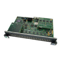
Fast Ethernet modules
Brand:
Enterasys
| Category:
Network Hardware
| Size: 0.67 MB
Table of Contents
Fcc Notice
4
Industry Canada Notice
4
Declaration of Conformity
7
Table of Contents
9
Figures
11
About this Guide
13
Important Notices
13
Using this Guide
13
Related Documents
14
Structure of this Guide
14
Document Conventions
15
Getting Help
16
Important Notice
17
H302-48 and 6H303-48 Modules
18
Connectivity
19
Runtime IP Address Discovery
19
Half-Duplex/Full-Duplex Auto-Negotiation
19
Smarttrunk
19
Remote Monitoring (RMON)
20
Broadcast Suppression
20
Port/Vlan Redirect Functions
20
Traffic Rate Limiting
21
Flow Control
21
GARP Switch Operation
22
802.1 Port Priority
22
Distributed Chassis Management
22
Management
23
Switching Options
23
Standards Compatibility
24
LANVIEW Diagnostic Leds
24
Smarttrunk Feature
25
10BASE-T Network
25
100BASE-TX Network
26
Contents of Module Carton
28
Installing Optional FLASH Upgrade
28
Installing the Module into the Matrix E7 Chassis
28
Unpacking the Module
28
Installing a Module into the Matrix E7 Chassis
30
Installing the Module into the 6C105 Chassis
31
Installing a Module into the 6C105 Chassis
32
Connecting to the Network
33
Connecting UTP Cables to the 6H302-48
33
Connecting a Twisted Pair Segment to the 6H302-48
34
Connecting UTP Cables to the 6H303-48
35
Crossover Cable RJ45 Pinouts
35
Straight-Through Cable RJ45 Pinouts
35
Connecting a Twisted Pair Segment to the 6H303-48
36
Completing the Installation
37
LANVIEW Leds
39
Troubleshooting Checklist
39
Using LANVIEW
39
LANVIEW Leds (both Modules)
40
Troubleshooting Checklist
43
Using the RESET Button
45
A-1 6H302-48 / 6H303-48 Specifications
47
6H302-48 / 6H303-48 Specifications
48
A-3 Compliance Standards
49
A.3 Regulatory Compliance
49
COM Port Pinout Assignments
49
Regulatory Compliance
49
Required Tools
51
B-1 Mode Switch Location
52
Setting the Mode Switches
52
B-2 FLASH Module Location
54
B.3 FLASH Upgrade
54
Locating the FLASH Module
54
Installing the FLASH Module
55
FLASH Upgrade
54
Index
57
Advertisement
Related Products
Enterasys SmartSwitch 6000
Enterasys SmartSwitch 6G302-06
Enterasys SmartSwitch 6G306-06
Enterasys Matrix 7G4270-09
Enterasys Matrix 7G4270-10
Enterasys Matrix 7G4270-12
Enterasys Matrix 7GR4270-12
Enterasys Matrix 7G4202-72
Enterasys Matrix 7G4282-49
Enterasys Matrix 7G4282-41
Enterasys Categories
Switch
Network Router
Network Hardware
Wireless Access Point
Software
More Enterasys Manuals
Login
Sign In
OR
Sign in with Facebook
Sign in with Google
Upload manual
Upload from disk
Upload from URL