Sign In
Upload
Manuals
Brands
Emerson Manuals
Measuring Instruments
Rosemount 5408
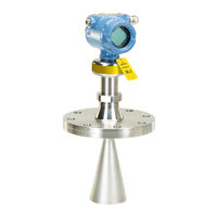
Emerson Rosemount 5408 Manuals
Manuals and User Guides for Emerson Rosemount 5408. We have
12
Emerson Rosemount 5408 manuals available for free PDF download: Reference Manual, Quick Start Manual
Emerson Rosemount 5408 Reference Manual (260 pages)
Level Transmitters Non-Contacting Radar
Brand:
Emerson
| Category:
Transmitter
| Size: 35.95 MB
Table of Contents
Table of Contents
5
Chapter 1 Introduction
11
Using this Manual
11
Product Recycling/Disposal
11
Chapter 2 Transmitter Overview
13
Measurement Principle
13
Process Characteristics
14
Dielectric Constant
14
Foam and Turbulence
14
Dust
15
Solid Surface
15
Vessel Characteristics
16
In-Tank Obstructions
16
Tank Shape
16
Application Examples
16
Components of the Transmitter
18
System Integration
20
Chapter 3 Mechanical Installation
23
Safety Messages
23
Confirm Approval Type
23
Installation Considerations
24
Mounting Position
24
Free Space Requirements
25
Antenna Size
26
Antenna Inclination
26
Non-Metallic Tanks
27
Beam Width and Beam Angle
27
Nozzle Requirements
29
Still Pipe/Chamber Installations
31
Ball Valve Installation
34
Mounting Preparations
35
Assemble the Segmented Cone Antenna
35
Shorten the Extended Cone Antenna
36
Mount the Cone Antenna
38
Protective Cap
38
Flanged Version
39
Flanged Version with Air Purge Ring (Option Code PC1)
40
Threaded Version, Antenna Diameter (D) < Thread Diameter (D)
41
Threaded Version, Antenna Diameter (D) > Thread Diameter (D)
44
Bracket Mounting
46
Align Transmitter Head
48
Mount the Process Seal Antenna
50
Flanged Version
50
Tri-Clamp Version
52
Mount the Parabolic Antenna
53
Flanged Version
53
Threaded Version
55
Welded Version
59
Adjust the Inclination of the Antenna
63
Connect the Air Purging
66
Adjust Display Orientation (Optional)
67
Chapter 4 Electrical Installation
69
Safety Messages
69
Cable Selection
69
Cable Gland/Conduit
70
Power Supply
70
Load Limitations
70
Hazardous Areas
70
Wiring Diagram
71
Grounding
72
Connect Wiring and Power up
73
Optional Devices
76
Rosemount ™ 333 HART Tri-Loop
76
Chapter 5 Configuration
79
Safety Messages
79
Overview
79
System Readiness
79
Confirm Correct Device Driver
79
Get Started with Your Preferred Configuration Tool
80
Configuration Tools
80
Rosemount Radar Master Plus
81
AMS Device Manager
81
Field Communicator
82
Confirm HART Revision Capability
82
Switch HART Revision Mode
82
Configure Device Using Guided Setup
83
Configure Using Rosemount Radar Master Plus
83
Configure Using AMS Device Manager
83
Configure Using Field Communicator
83
Verify Level
83
Use Rosemount Radar Master Plus
84
Use AMS Device Manager and Field Communicator
84
Establish Multidrop Communication
85
Use Rosemount Radar Master Plus
85
Use AMS Device Manager
85
Use Field Communicator
85
Use with the Rosemount 333 HART Tri-Loop
85
Chapter 6 Operation
87
LCD Display Screen Messages
87
Startup Screen Sequence
87
Variable Screens
88
Set up the LCD Display
89
Use Rosemount Radar Master Plus
89
Use AMS Device Manager and Field Communicator
89
View Measurement Data
89
Reference Manual
90
Use AMS Device Manager and Field Communicator
90
Interpret Measurement Status
90
Device Status
91
Check Device Status
91
Chapter 7 Service and Troubleshooting
95
Safety Messages
95
Diagnostic Messages
95
Troubleshooting Guide
101
Service and Troubleshooting Tools
107
Using the Echo Curve
107
Managing Disturbance Echoes
111
Perform an Analog Loop Test
117
Use the TEST Terminal
118
Calibrate Analog out
120
Save a Backup File of the Device Configuration
120
Download Configuration from File to Device
121
Restore to Default Settings
121
Use the Simulation Mode
121
View Input Registers
122
View/Edit Holding Registers
122
Write Protect a Transmitter
123
Application Challenges
124
Handling Disturbances at Top of Tank
124
Tracking of Weak Surface Echoes Close to Tank Bottom
126
Handling Ghost Echoes in Still Pipes
129
Handling Strong Double Bounce Echoes
130
Replace the Transmitter Head
132
Cleaning or Replacing the PTFE Sealing
134
Flanged Version
135
Tri Clamp Version
136
Service Support
138
Chapter 8 Safety Instrumented Systems (4-20 Ma Only)
141
Safety Messages
141
Terms and Definitions
141
Safety Instrumented System (SIS) Certification
143
Safety Certified Identification
144
Installation
145
Measuring Range
146
Configuration
146
Prerequisites
146
Configure Device Using Guided Setup
146
Set Operational Mode
146
Enable Safety Mode
147
Alarm and Saturation Levels
147
Site Acceptance
148
Proof-Testing
148
Overview
148
Perform 1-Point Level and Analog Output Verification
149
Perfom 2-Point Level and Analog Output Verification
152
Perform Analog Output Verification
154
Perform Level Deviation Monitoring
154
Product Repair
155
Specifications
155
Failure Rate Data
155
Safety Deviation
155
Transmitter Response Time
155
Diagnostic Test Interval
155
Turn-On Time
155
Appendix A Specifications and Reference Data
157
Performance Specifications
157
General
157
Measuring Range
158
A.1.2 Measuring Range
158
Environment
160
A.1.3 Environment
160
Functional Specifications
161
General
161
Display and Configuration
161
A.2 Functional Specifications
161
4-20 Ma HART
163
Power Consumption
163
Diagnostics
165
A.2.4 Diagnostics
165
Process Temperature and Pressure Rating
166
Temperature Limits
167
Flange Rating
168
A.2.7 Flange Rating
168
Conditions Used for Flange Strength Calculations
169
Air Purging
171
A.2.9 Air Purging
171
System Integration
172
A.2.10 System Integration
172
Physical Specifications
173
Material Selection
173
Engineered Solutions
173
Housing and Enclosure
173
A.3 Physical Specifications
173
Tank Connection
174
Flange Dimensions
174
Antenna Versions
174
Material Exposed to Tank Atmosphere
174
A.3.4 Tank Connection
174
Ordering Information
175
Rosemount 5408 Level Transmitter
175
A.4 Ordering Information
175
Rosemount 5408:SIS Level Transmitter
180
Availability of Process Connections
186
Spare Parts and Accessories
188
Accessories
195
A.6.1 Accessories
195
Dimensional Drawings
196
A.7 Dimensional Drawings
196
A.7.1 Standard Flanges
200
Standard Flanges
200
Appendix B Product Certifications
203
European Directive Information
203
Safety Instrumented Systems (SIS)
203
Telecommunication Compliance
203
Fcc
204
Radio Equipment Directive (RED) 2014/53/EU
205
Installing Equipment in North America
206
U.s.a
206
E5 Explosionproof (XP), Dust-Ignitionproof (DIP)
206
I5 Intrinsic Safety (IS), Non-Incendive (NI)
208
Canada
209
E6 Explosionproof, Dust-Ignitionproof
209
B.9 Canada
209
I6 Intrinsically Safe and Non-Incendive Systems
211
Europe
213
E1 ATEX Flameproof
213
B.10 Europe
213
I1 ATEX Intrinsic Safety
214
N1 ATEX Type N: Non-Sparking
216
International
216
E7 Iecex Flameproof
216
I7 Iecex Intrinsic Safety
217
N7 Iecex Type N: Non-Sparking
219
Brazil
219
E2 INMETRO Flameproof
219
I2 INMETRO Intrinsic Safety
220
N2 INMETRO Type N: Non-Sparking
220
China
221
E3 Flameproof
221
I3 Intrinsic Safety
221
N3 Type N: Non-Sparking
221
B.13 China
221
India
222
Intrinsic Safety
222
Flameproof Safety
222
Intrinsic Safety and Flameproof
222
Republic of Korea
222
IP Intrinsic Safety
222
B.14 India
222
Additional Certifications
223
QT Safety-Certified to IEC 61508:2010 with Certificate of FMEDA Data
223
Suitable for Intended Use
223
U1 Overfill Prevention
223
B.16 Additional Certifications
223
Installation Drawings
224
B.17 Installation Drawings
224
Appendix C Configuration Parameters
231
Menu Tree
231
Device Setup
233
HART Protocol
233
Burst Mode
233
Units
234
Analog Output
234
C.2.2 Units
234
Display
235
Security
235
Write Protection
235
Device Information
236
C.2.6 Device Information
236
Level Setup
237
Geometry
237
C.3 Level Setup
237
Environment
245
C.3.2 Environment
245
Volume
246
Scaled Variable
246
C.3.3 Volume
246
Antenna
247
C.3.5 Antenna
247
Advanced
249
C.3.6 Advanced
249
Alert Setup
255
C.4 Alert Setup
255
C.4.3 High/Low User Defined Alert
256
Advertisement
Emerson Rosemount 5408 Reference Manual (226 pages)
Level Transmitters. Non-Contacting Radar
Brand:
Emerson
| Category:
Measuring Instruments
| Size: 28.71 MB
Table of Contents
Table of Contents
3
Using this Manual
13
Product Recycling/Disposal
13
2Section 2: Transmitter Overview
13
Measurement Principle
15
Process Characteristics
16
Dielectric Constant
16
Foam and Turbulence
16
Condensation
17
Dust
17
Solid Surface
17
Vessel Characteristics
18
In-Tank Obstructions
18
Tank Shape
18
Application Examples
18
Components of the Transmitter
21
System Integration
22
Safety Messages
23
Confirm Approval Type
24
Review Mounting Considerations
24
Mounting Position
24
Free Space Requirements
25
Antenna Size
26
Antenna Inclination
26
Non-Metallic Tanks
26
Beam Width and Beam Angle
27
Nozzle Requirements
28
Still Pipe/Chamber Installations
31
Ball Valve Installation
32
Review Mounting Preparations
33
Assemble the Segmented Cone Antenna
33
Shorten the Extended Cone Antenna
35
Mount the Cone Antenna
36
Flanged Version
37
Flanged Version with Air Purge Ring (Option Code PC1)
38
Threaded Version
40
Bracket Mounting
46
Align Transmitter Head
49
Mount the Process Seal Antenna
51
Flanged Version
51
Tri Clamp Version
53
Mount the Parabolic Antenna
54
Flanged Version
55
Threaded Version
56
Welded Version
60
Adjust the Inclination of the Antenna
65
Connect the Air Purging
68
Adjust Display Orientation (Optional)
69
Safety Messages
71
Cable Selection
72
Cable Gland/Conduit
72
Power Supply
72
Hazardous Areas
72
Wiring Diagram
73
Grounding
74
Transmitter Housing
74
Signal Cable Shield Grounding
74
Wiring and Power up
75
Electrical Installation
76
Optional Devices
78
Rosemount ™ 333 HART Tri-Loop
78
Safety Messages
79
Overview
79
System Readiness
80
Confirm Correct Device Driver
80
Get Started with Your Preferred Configuration Tool
80
Rosemount Radar Master Plus
80
AMS Device Manager
81
Field Communicator
82
Confirm HART Revision Capability
82
Switch HART Revision Mode
82
Configure Device Using Guided Setup
83
Verify Level
84
Establish Multidrop Communication
85
Use with the Rosemount 333 HART Tri-Loop
86
LCD Display Screen Messages
87
Startup Screen Sequence
87
Variable Screens
88
Set up the LCD Display
88
View Measurement Data
89
View Current Measurement Values
89
Interpret Measurement Status
90
Check Device Status
90
Safety Messages
93
Diagnostic Messages
94
Troubleshooting Guide
99
Service and Troubleshooting Tools
104
Use the Echo Curve
104
Manage Disturbance Echoes
107
Perform an Analog Loop Test
112
Use the TEST Terminal
113
Calibrate Analog out
114
Save and Load Configuration Files
115
Restore to Default Settings
115
Use the Simulation Mode
116
View Input Registers
116
10View/Edit Holding Registers
116
Write Protect a Transmitter
117
Application Challenges
118
Handling Disturbances at Top of Tank
118
Tracking of Weak Surface Echoes Close to Tank Bottom
120
Handling Ghost Echoes in Still Pipes
122
Handling Strong Double Bounce Echoes
123
Transmitter Head Replacement
124
Cleaning or Replacing the PTFE Sealing
127
Remove from Service
127
Cleaning
127
Replacing
127
Service Support
131
Safety Messages
133
Terms and Definitions
134
Safety Instrumented Systems
134
Safety Instrumented System (SIS) Certification
136
Safety Certified Identification
137
Installation
138
Measuring Range
138
Configuration
138
Prerequisites
138
Configure Device Using Guided Setup
138
Set Operational Mode
138
Enable Safety Mode
139
Alarm and Saturation Levels
140
Site Acceptance
140
Proof-Testing
140
Overview
140
Tools Required
141
1-Point Level and Analog Output Verification
142
2-Point Level and Analog Output Verification
143
Analog Output Verification
144
Level Deviation Monitoring
145
Product Repair
145
Specifications
145
Performance Specifications
147
General
147
Measuring Range
147
Environment
149
Functional Specifications
149
General
149
Display and Configuration
149
4-20 Ma HART
150
Diagnostics
151
Process Temperature and Pressure Rating
152
Temperature Limits
153
Flange Rating
153
Conditions Used for Flange Strength Calculations
153
Air Purging
153
A.2.10System Integration
154
Physical Specifications
154
Material Selection
154
Engineered Solutions
154
Housing and Enclosure
154
Tank Connection
155
Flange Dimensions
155
Antenna Versions
155
Material Exposed to Tank Atmosphere
155
Ordering Information
156
Spare Parts and Accessories
167
Dimensional Drawings
175
Standard Flanges
179
European Directive Information
181
Safety Instrumented Systems (SIS)
181
Telecommunication Compliance
181
Fcc
181
Radio Equipment Directive (RED) 2014/53/EU
182
Installing Equipment in North America
182
U.s.a
182
Canada
184
B.10Europe
186
Europe
186
B.11International
188
International
188
B.12Brazil
189
B.13China
189
Brazil
189
China
189
B.14Republic of Korea
190
B.15Additional Certifications
190
B.16Installation Drawings
190
Republic of Korea
190
Additional Certifications
190
Installation Drawings
190
Menu Tree
197
Device Setup
199
HART ® Protocol
199
Units
199
Analog Output
199
Display
200
Security
201
Device Information
201
Level Setup
201
Geometry
201
Environment
208
Volume
208
Scaled Variable
209
Antenna
210
Advanced
211
Alert Setup
215
Measurement Recovery
215
Signal Quality Alert
215
High/Low User Defined Alert
216
Emerson Rosemount 5408 Reference Manual (274 pages)
Level Transmitters, Non-Contacting Radar with HART Protocol
Brand:
Emerson
| Category:
Transmitter
| Size: 38.72 MB
Table of Contents
Table of Contents
5
Chapter 1 Introduction
9
Using this Manual
9
Product Recycling/Disposal
9
Chapter 2 Transmitter Overview
11
Measurement Principle
11
Process Characteristics
12
Vessel Characteristics
14
Application Examples
14
Components of the Transmitter
17
System Integration
18
Chapter 3 Mechanical Installation
21
Safety Messages
21
Confirm Approval Type
21
Installation Considerations
22
Mounting Preparations
32
Mount the Cone Antenna
36
Mount the Process Seal Antenna
49
Mount the Parabolic Antenna
53
Adjust Display Orientation (Optional)
71
Chapter 4 Electrical Installation
73
Safety Messages
73
Hazardous Areas
74
Prepare the Electrical Connections
74
Connect Wiring and Power up
78
Optional Devices
81
Chapter 5 Configuration
83
Safety Messages
83
Overview
83
System Readiness
84
Get Started with Your Preferred Configuration Tool
85
Confirm HART ® Revision Capability
87
Configure Transmitter Using Guided Setup
87
Verify Level
88
Establish Multidrop Communication
90
Use with the Rosemount 333 HART ® Tri-Loop
91
Write Protect a Transmitter
92
Chapter 6 Operation
93
LCD Display Screen Messages
93
Set up the LCD Display
95
View Measurement Data
95
Device Status
97
Chapter 7 Service and Troubleshooting
101
Safety Messages
101
Diagnostic Messages
101
Troubleshooting Guides
107
Service and Troubleshooting Tools
113
Application Challenges
132
Replace the Transmitter Head
139
Cleaning or Replacing the PTFE Sealing
141
Service Support
146
Chapter 8 Safety Instrumented Systems (SIS) Requirements
147
Safety Messages
147
Terms and Definitions
148
Safety Instrumented System (SIS) Certification
149
Safety Certified Identification
151
Installation
152
Configuration
152
Site Acceptance
154
Perform Proof Test for SIS Applications
155
Specifications
161
Appendix A Specifications and Reference Data
163
Performance Specifications
163
Functional Specifications
166
Physical Specifications
177
Ordering Information
180
Availability of Process Connections
191
Spare Parts and Accessories
193
Dimensional Drawings
201
Appendix B Product Certifications
211
European Directive Information
211
Safety Instrumented Systems (SIS)
211
Ordinary Location Certification
211
Telecommunication Compliance
211
Fcc
212
Radio Equipment Directive (RED) 2014/53/EU
213
Installing Equipment in North America
213
Usa
214
Canada
217
Europe
221
International
225
Brazil
228
China
229
Technical Regulations Customs Union (EAC)
230
Japan
233
India
233
Republic of Korea
234
Additional Certifications
235
Installation Drawings
238
Appendix C Configuration Parameters
249
Menu Tree
249
Device Setup
251
Level Setup
255
Alert Setup
271
Advertisement
Emerson Rosemount 5408 Reference Manual (256 pages)
Level Transmitter, Non-Contacting Radar with FOUNDATION Fieldbus Protocol
Brand:
Emerson
| Category:
Transmitter
| Size: 32.9 MB
Table of Contents
Table of Contents
5
Chapter 1 Introduction
9
Using this Manual
9
Product Recycling/Disposal
9
Chapter 2 Transmitter Overview
11
Measurement Principle
11
Process Characteristics
12
Vessel Characteristics
14
Application Examples
14
Components of the Transmitter
16
System Integration
18
Chapter 3 Mechanical Installation
19
Safety Messages
19
Confirm Approval Type
20
Installation Considerations
20
Mounting Preparations
30
Mount the Cone Antenna
34
Bracket Mounting
43
Mount the Process Seal Antenna
46
Mount the Parabolic Antenna
49
Adjust Display Orientation (Optional)
64
Chapter 4 Electrical Installation
65
Safety Messages
65
Hazardous Areas
66
Prepare the Electrical Connections
66
Wiring Diagram
68
Connect Wiring and Power up
69
Chapter 5 Configuration
73
Safety Messages
73
Overview
73
System Readiness
74
Get Started with Your Preferred Configuration Tool
74
Change Device Mode
76
Configure Transmitter Using Guided Setup
77
Verify Level
78
Write Protect a Transmitter
79
Chapter 6 Operation
81
LCD Display Screen Messages
81
Set up the LCD Display
82
View Measurement Data
83
Device Status
85
Chapter 7 Service and Troubleshooting
89
Safety Messages
89
Diagnostic Messages
89
FOUNDATION ™ Fieldbus Error Messages
96
Troubleshooting Guides
99
Service and Troubleshooting Tools
105
Application Challenges
119
Replace the Transmitter Head
127
Cleaning or Replacing the PTFE Sealing
129
Service Support
133
Appendix A Specifications and Reference Data
135
Performance Specifications
135
Functional Specifications
138
Cable Selection
140
Physical Specifications
148
Ordering Information
151
Availability of Process Connections
156
Spare Parts and Accessories
157
Dimensional Drawings
164
Appendix B Product Certifications
173
European Directive Information
173
Ordinary Location Certification
173
Telecommunication Compliance
173
Fcc
173
Radio Equipment Directive (RED) 2014/53/EU
175
Installing Equipment in North America
175
Usa
175
Canada
181
Europe
187
International
192
Additional Certifications
196
Installation Drawings
197
Appendix C Configuration Parameters
207
Menu Tree
207
Device Setup
208
Write Protection
210
Level Setup
211
Tank Shape
214
Alert Setup
228
Foundation
233
Appendix D FOUNDATION Fieldbus Block Information
233
Resource Block
233
Analog Input Block
239
Measurement Transducer Block
248
Register Transducer Block
252
Supported Units
254
D.5 Supported Units
254
Emerson Rosemount 5408 Reference Manual (216 pages)
Level Transmitters
Brand:
Emerson
| Category:
Transmitter
| Size: 36.22 MB
Table of Contents
Table of Contents
5
Chapter 1 Introduction
7
Using this Manual
7
NAMUR NE 53 Revision History
8
Product Certifications
8
Product Recycling/Disposal
8
Chapter 2 Transmitter Overview
9
Measurement Principle
9
Process Characteristics
9
Vessel Characteristics
11
Application Examples
11
Components of the Transmitter
13
System Integration
14
Chapter 3 Mechanical Installation
17
Safety Messages
17
Confirm Approval Type
18
Installation Considerations
18
Mounting Preparations
27
Mount the Cone Antenna
31
Mount the Process Seal Antenna
43
Mount the Parabolic Antenna
47
Adjust Display Orientation (Optional)
64
Chapter 4 Electrical Installation
67
Safety Messages
67
Hazardous Areas
68
Prepare the Electrical Connections
68
Connect Wiring and Power up
71
Optional Devices
75
Chapter 5 Configuration
77
Safety Messages
77
Overview
77
Configuration Tools
77
Confirm Correct Device Driver
78
Rosemount Radar Master Plus
78
Confirm HART ® Revision Capability
79
Configure Transmitter Using Guided Setup
79
Run Verify Level
80
Multidrop Communication
80
Use with the Rosemount 333 HART ® Tri-Loop
80
Write Protect a Transmitter
81
Chapter 6 Operation
83
LCD Display Screen Messages
83
Select the Display Variables
84
View Measurement Data
85
Check Device Status
85
Smart Echo Level Test
88
Service and Troubleshooting
91
Safety Messages
91
Diagnostic Messages Per NAMUR NE 107
92
Troubleshooting Guides
103
Service and Troubleshooting Tools
118
Application Challenges
129
Replace the Transmitter Head
140
Cleaning or Replacing the PTFE Sealing
143
Service Support
147
Appendix A Specifications and Reference Data
149
Performance Specifications
149
Functional Specifications
152
Physical Specifications
161
Spare Parts List - Transmitter Head
163
Spare Parts List - Antenna
168
Availability of Process Connections
175
Accessories
178
Dimensional Drawings
179
Appendix B Configuration Parameters
189
Menu Tree
189
Device Setup
190
Level Setup
194
Alert Setup
212
Emerson Rosemount 5408 Reference Manual (61 pages)
Level Transmitters, Non-Contacting Radar
Brand:
Emerson
| Category:
Transmitter
| Size: 6.03 MB
Table of Contents
Table of Contents
3
Models Covered
13
Using this Manual
13
Product Recycling/Disposal
14
Measurement Principle
15
Process Characteristics
16
Dielectric Constant
16
Foam and Turbulence
16
Condensation
16
Vessel Characteristics
16
In-Tank Obstructions
16
Tank Shape
17
Application Examples
17
Components of the Transmitter
19
System Integration
20
Safety Messages
21
Review Mounting Considerations
22
Mounting Position
22
Antenna Size
23
Inclination of Antenna
23
Non-Metallic Tanks
23
Beam Width and Beam Angle
24
Nozzle Requirements
25
Free Space Requirements
27
Installation in Still Pipe/Chamber
28
Ball Valve Installation
29
Review Mounting Preparations
30
Assemble the Segmented Cone Antenna
30
Shorten the Extended Cone Antenna
32
Mount the Cone Antenna
33
Flanged Version
34
Flanged Version with Air Purge Ring
35
Threaded Version
37
Bracket Mounting
43
Overview
48
Installation
49
Emerson Rosemount 5408 Quick Start Manual (37 pages)
Level Transmitter
Brand:
Emerson
| Category:
Transmitter
| Size: 7.12 MB
Table of Contents
About this Guide
2
Confirm Approval Type
4
Mount the Transmitter
5
Bracket Mounting
14
Align Transmitter Head
18
Adjust Display Orientation (Optional)
20
Prepare the Electrical Connections
21
Cable Selection
21
Power Supply
21
Power Consumption
21
Wiring Diagram
23
Connect Wiring and Power up
26
Configure Transmitter Using Guided Setup
30
Assemble the Segmented Cone Antenna
32
Emerson Rosemount 5408 Quick Start Manual (36 pages)
Level Transmitters, Parabolic Antenna
Brand:
Emerson
| Category:
Transmitter
| Size: 12.99 MB
Table of Contents
Table of Contents
2
About this Guide
3
Confirm Approval Type
5
Components of the Parabolic Antenna
6
Mount the Transmitter
8
Adjust the Inclination of the Antenna
17
Connect the Air Purging
20
Adjust Display Orientation (Optional)
21
Prepare the Electrical Connections
22
Connect Wiring and Power up
29
Configure Transmitter Using Guided Setup
33
Emerson Rosemount 5408 Quick Start Manual (36 pages)
Level Transmitters
Brand:
Emerson
| Category:
Transmitter
| Size: 7.07 MB
Table of Contents
Table of Contents
2
About this Guide
3
Confirm Approval Type
5
Mount the Transmitter
6
Align Transmitter Head
16
Adjust Display Orientation (Optional)
18
Prepare the Electrical Connections
19
Connect Wiring and Power up
26
Configure Transmitter Using Guided Setup
30
Assemble the Segmented Cone Antenna
32
Emerson Rosemount 5408 Quick Start Manual (36 pages)
Cone Antenna
Brand:
Emerson
| Category:
Antenna
| Size: 7.19 MB
Table of Contents
Table of Contents
2
About this Guide
3
Confirm Approval Type
5
Mount the Transmitter
6
Align Transmitter Head
18
Adjust Display Orientation (Optional)
20
Prepare the Electrical Connections
21
Connect Wiring and Power up
28
Configuration
32
Assemble the Segmented Cone Antenna
34
Emerson Rosemount 5408 Quick Start Manual (28 pages)
Level Transmitter with Modbus Protocol
Brand:
Emerson
| Category:
Transmitter
| Size: 6.53 MB
Table of Contents
Table of Contents
2
About this Guide
3
Confirm Approval Type
5
Components of the Parabolic Antenna
6
Mount the Transmitter
7
Adjust the Inclination of the Antenna
11
Plug and Seal the Air Purge Entry
14
Adjust Display Orientation (Optional)
15
Prepare the Electrical Connections
16
Connect Wiring and Power up
19
Performance Specifications
23
Functional Specifications
25
Physical Specifications
27
Emerson Rosemount 5408 Quick Start Manual (20 pages)
Process Seal Antenna
Brand:
Emerson
| Category:
Transmitter
| Size: 5.35 MB
Table of Contents
Table of Contents
3
Confirm Approval Type
3
Mount the Transmitter
4
Align Transmitter Head
8
Adjust Display Orientation (Optional)
10
Prepare the Electrical Connections
11
Connect Wiring and Power up
12
Configure Transmitter Using Guided Setup
17
Advertisement
Related Products
Emerson Rosemount 5900
Emerson Rosemount 5900S Series
Emerson 586505000
Emerson 586505500
Emerson Rosemount 56
Emerson 56WM WirelessHART SensEnable
Emerson Rosemount 54eA
Emerson ROSEMOUNT370XA
Emerson Rosemount 8750W
Emerson Rosemount 3051 CF Series
Emerson Categories
Controller
Control Unit
Transmitter
Measuring Instruments
Fan
More Emerson Manuals
Login
Sign In
OR
Sign in with Facebook
Sign in with Google
Upload manual
Upload from disk
Upload from URL