Sign In
Upload
Manuals
Brands
Daikin Manuals
Air Conditioner
FTXS25CAVMB
Daikin FTXS25CAVMB Manuals
Manuals and User Guides for Daikin FTXS25CAVMB. We have
4
Daikin FTXS25CAVMB manuals available for free PDF download: Service Manual, Operation Manual
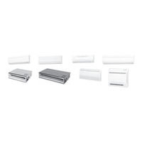
Daikin FTXS25CAVMB Service Manual (398 pages)
Brand:
Daikin
| Category:
Air Conditioner
| Size: 14.81 MB
Table of Contents
Table of Contents
3
Introduction
8
Safety Cautions
8
Caution in Repair
8
Cautions Regarding Products after Repair
9
Inspection after Repair
10
Using Icons
11
Using Icons List
11
Part 1 List of Functions
12
List of Functions
13
Part 2 Specifications
20
Specifications
21
Outdoor Units
21
BP Unit
22
Indoor Units
23
Ceiling Mounted Cassette Type
31
Part 3 Printed Circuit Board Connector Wiring Diagram
34
Printed Circuit Board Connector Wiring Diagram
35
Outdoor Unit RMXS 112/140/160 E7V3B
35
Branch Provider Unit
40
Wall Mounted Type 20/25/35/50 Class - D Series
41
Wall Mounted Type 20/25/35 Class - C Series
44
Wall Mounted Type 50/60/71 Class - E(B) Series
46
Duct Connected Type
48
Floor / Ceiling Suspended Dual Type
50
Floor Standing Type
53
Ceiling Mounted Cassette 600×600 Type
56
Ceiling Suspended Type
58
Part 4 Refrigerant Circuit
60
Refrigerant Circuit
61
Outdoor Units
61
Refrigerant Circuit Part
61
BP Units
63
Functional Parts Layout
64
Outdoor Units
64
Refrigerant Flow for each Operation Mode
65
Cooling Operation
65
Heating Operation
66
Cooling Oil Return Operation
67
Heating Oil Return Operation & Defrost Operation
68
Part 5 Function
70
Operation Mode
71
Basic Control
72
Normal Operation
72
Compressor PI Control
73
Electronic Expansion Valve PI Control
76
Cooling Operation Fan Control
77
Special Control
78
Startup Control
78
Oil Return Operation
79
Defrosting Operation
81
Pump-Down Residual Operation
82
Restart Standby
82
Stopping Operation
83
Protection Control
84
High Pressure Protection Control
84
Low Pressure Protection Control
85
Discharge Pipe Protection Control
86
Inverter Protection Control
87
Freeze-Up Protection Control
88
Dew Condensation Prevention Control
89
Other Control
90
Demand Operation
90
Heating Operation Prohibition
90
BP Unit Control
91
BP Unit Command Conversion
91
BP Unit Electronic Expansion Valve Control
92
Full Closing of Electronic Expansion Valves
93
SH Control in Cooling Operation
94
SC Control in Heating Operation
95
Heat Exchanger Isothermal Control in Heating Operation
95
Indoor Unit (RA Models)
96
Power-Airflow Dual Flaps, Wide Angle Louvers and Auto-Swing
96
Fan Speed Control for Indoor Units
97
Programme Dry Function
98
Automatic Operation
99
Thermostat Control
100
Night Set Mode
101
ECONO Mode
102
Intelligent Eye
103
HOME LEAVE Operation
105
Inverter POWERFUL Operation
106
Other Functions
107
Indoor Unit (Skyair Models)
109
Function Outline
109
Electric Function Parts
110
Function Details
111
Part 6 Test Operation
122
Test Operation
123
Procedure and Outline
123
Check Operation
126
Outdoor Unit PCB Layout
128
Field Setting
129
Field Setting from Outdoor Unit
129
Detail of Setting Mode
138
Field Setting for Skyair Indoor Unit
147
Explanation
147
Field Setting
148
Initial Setting Contents
149
Local Setting Mode Number
150
Detailed Explanation of Setting Modes
151
Centralized Group No. Setting
155
Maintenance Mode Setting
156
Test Operation and Field Setting for RA Indoor Unit
157
Test Operation from the Remote Control
157
Jumper Settings
158
Part 7 System Configuration
160
System Configuration
161
Operation Instructions
161
Instruction
162
RMXS Series
162
Wall Mounted, Duct, Floor/Ceiling, Floor Standing Type
163
Safety Precautions
164
Installation Site
165
Electrical Work
165
Names of Parts
166
Indoor Unit
169
Outdoor Unit
170
Remote Control
171
To Set the Clock
186
To Change the Air Flow Rate Setting
188
Adjusting the Air Flow Direction
189
Air Flow Selection
198
Powerful Operation
199
Outdoor Unit Silent Operation
200
Econo Operation
201
Intelligent Eye Operation
204
Timer Operation
210
To Use on Timer Operation
211
To Combine on Timer and off Timer
211
Note for Multi System
212
Priority Room Setting
213
Care and Cleaning
214
Air Filter
215
Before a Long Idle Period
216
Front Panel
217
Cleaning the Air Filter
223
Front Grille
230
Troubleshooting
233
These Cases Are Not Troubles
233
Ceiling Mounted Cassette Type
238
Temperature Setting
243
Fan Speed Control
243
Ceiling Suspended Type
249
Operation Range
252
Air Flow Direction Adjust
254
Part 8 Troubleshooting
260
Caution for Diagnosis
262
Troubleshooting with the Operation Lamp (RA Indoor Unit)
262
Troubleshooting with the LED on the Skyair Indoor Unit
263
Troubleshooting with the LED on the Outdoor Unit
264
Troubleshooting with the LED on the BP Unit
265
Service Check Function
266
RA Indoor Unit Infrared Remote Control
266
Skyair Indoor Unit INSPECTION/TEST Button
270
Skyair Indoor Unit Wired Remote Control
271
Skyair Indoor Unit Infrared Remote Control
272
Service Check Function
273
Sky Air Indoor Unit Error Codes and LED Indication
274
Malfunction Code Indication by Outdoor Unit PCB
275
List of Malfunction Code
279
Troubleshooting for RA Indoor Unit
281
Indoor Unit PCB Abnormality
281
Freeze-Up Protection Control or High Pressure Control
282
Fan Motor or Related Abnormality
284
Thermistor or Related Abnormality (Indoor Unit)
287
Shutter Drive Motor / Shutter Limit Switch Abnormality
288
Check
289
Thermistor Resistance Check
290
Hall IC Check
291
Troubleshooting for Skyair Indoor Unit
292
Indoor Unit PCB Abnormality
292
Malfunction of Drain Water Level System (Float Type)
293
Malfunction of Drain System
295
Indoor Unit Fan Motor Lock
296
Malfunction of Indoor Unit Fan Motor
297
Swing Flap Motor Malfunction / Lock
299
Malfunction of Capacity Setting
301
Malfunction of Heat Exchanger Thermistor (R2T)
302
Malfunction of Heat Exchanger Thermistor (R3T)
303
Malfunction of Suction Air Thermistor
304
Malfunction of Remote Control Thermistor
305
Transmission Error (between Indoor Unit and Remote Control)
306
Transmission Error (between Main and Sub Remote Control)
307
Malfunction of Field Setting Switch
308
Check
309
Troubleshooting for BP Unit
311
Malfunction of Electronic Expansion Valve
311
Faulty BP Unit PCB
312
Faulty BP Liquid or Gas Pipe Thermistor
313
Transmission Error between Indoor Unit and BP Unit
314
Transmission Error between Outdoor Unit and BP Unit
316
Check
317
Troubleshooting for Outdoor Unit
318
Faulty Outdoor Unit PCB
318
Actuation of High Pressure Switch
319
Actuation of Low Pressure Sensor
321
Compressor Motor Lock
323
Malfunction of Outdoor Unit Fan Motor
324
Malfunction of Moving Part of Electronic Expansion Valve (Y1E, Y3E)
325
Abnormal Discharge Pipe Temperature
327
Refrigerant Overcharged
328
Malfunction of Thermistor for Outdoor Air (R1T)
329
Malfunction of Discharge Pipe Thermistor (R2T)
330
Malfunction of Thermistor (R3T, R5T) for Suction Pipe1, 2
331
Malfunction of Thermistor (R4T) for Outdoor Unit Heat Exchanger
332
Malfunction of Thermistor (R7T) for Outdoor Unit Liquid Pipe
333
Malfunction of Subcooling Heat Exchanger Thermistor (R6T)
334
Malfunction of High Pressure Sensor
335
Malfunction of Low Pressure Sensor
336
Malfunction of PCB
337
Malfunction of Inverter Radiating Fin Temperature Rise
338
Inverter Compressor Abnormal
339
Inverter Current Abnormal
340
Inverter Start up Error
341
Malfunction of Transmission between Inverter and Control PCB
342
High Voltage of Capacitor in Main Inverter Circuit
343
Malfunction of Inverter Radiating Fin Temperature Rise Sensor
344
Faulty Combination of Inverter and Fan Driver
345
Low Pressure Drop Due to Refrigerant Shortage or Electronic Expansion Valve Failure
346
Power Supply Insufficient or Instantaneous Failure
348
Check Operation Not Executed
350
Malfunction of Transmission between Indoor Units and Outdoor Units
351
Malfunction of Transmission between Remote Control and Indoor Unit
353
Malfunction of Transmission between Main and Sub Remote Controls
354
Malfunction of Transmission between Indoor and Outdoor Units in the same System
355
Excessive Number of Indoor Units
357
Address Duplication of Central Remote Control
358
Malfunction of Transmission between Central Remote
359
Controller and Indoor Unit
359
System Is Not Set yet
361
Malfunction of System, Refrigerant System Address Undefined
362
Check
363
Thermistor Resistance / Temperature Characteristics
366
Pressure Sensor
368
Method of Replacing the Inverter's Power Transistors Modules
369
Part 9 Appendix
372
Piping Diagrams
373
Outdoor Units
373
BP Units
374
Indoor Units
375
Wiring Diagrams
380
Outdoor Units
380
BP Units
381
Indoor Units
382
Index
388
Drawings & Flow Charts
394
Advertisement
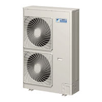
Daikin FTXS25CAVMB Service Manual (355 pages)
super multi nx
Brand:
Daikin
| Category:
Air Conditioner
| Size: 15.37 MB
Table of Contents
Table of Contents
3
Introduction
6
Safety Cautions
6
Used Icons
10
Part 1 List of Functions
12
List of Functions
13
Cooling Only Models
13
Heat Pump Models
18
Part 2 Specifications
24
Indoor Units - Cooling Only
25
Outdoor Units - Cooling Only
34
Indoor Units - Heat Pump
35
Outdoor Units - Heat Pump
46
Part 3 Printed Circuit Board Connector Wiring Diagram
48
Printed Circuit Board Connector Wiring Diagram
49
Wall Mounted Type
49
Duct Connected Type
58
Floor / Ceiling Suspended Dual Type
60
Floor Standing Type
63
Ceiling Suspended Type
65
Outdoor Units
67
Part 4 Function and Control
70
Main Functions
71
Frequency Principle
71
Power-Airflow Dual Flaps, Wide Angle Louvers and Auto-Swing
73
Operation Starting Control
75
Fan Speed Control for Indoor Units
76
Programme Dry Function
77
Automatic Operation
78
Thermostat Control
79
Night Set Mode
80
ECONO Mode
81
INTELLIGENT EYE (Wall Mounted Type Only)
82
HOME LEAVE Operation
84
Inverter POWERFUL Operation
85
Other Functions
86
Function of Main Structural Parts
88
Main Structural Parts
88
Function of Thermistor
89
Control Specification
93
Mode Hierarchy
93
Frequency Control
94
Controls at Mode Changing / Start-Up
97
Compressor Protection Function
98
Discharge Pipe Control
99
Input Current Control
99
Freeze-Up Protection Control
100
Heating Peak-Cut Control
100
Fan Control
101
Liquid Compression Protection Function 2
101
Defrost Control
102
Electronic Expansion Valve Control
103
Malfunctions
107
Forced Operation Mode
108
Wiring-Error Check
109
Additional Function
111
Part 5 Operation Manual
114
System Configuration
115
Operation Instructions
115
Instruction
116
FTK(X)S, FTXG, CTXG, FDK(X)S, FLK(X)S Series
116
Safety Precautions
117
FVXS Series
192
Air Flow Selection
203
FHQ Series
223
Temperature Setting
229
Fan Speed Control
229
Part 6 Service Diagnosis
236
Caution for Diagnosis
237
Troubleshooting with Operation Lamp
237
Problem Symptoms and Measures
239
Service Check Function
240
Check Method 1
240
Check Method 2
242
Code Indication on the Remote Control
244
Error Codes and Description of Fault
244
Troubleshooting
245
Indoor Units
245
Outdoor Units
246
Indoor Unit PCB Abnormality
247
Freeze-Up Protection Control or High Pressure Control
248
Fan Motor or Related Abnormality
250
Thermistor or Related Abnormality (Indoor Unit)
253
Front Panel Open / Close Fault
254
Signal Transmission Error (between Indoor and Outdoor Unit)
255
Unspecified Voltage (between Indoor and Outdoor Units)
257
Freeze-Up Protection Control
258
Outdoor Unit PCB Abnormality
260
OL Activation (Compressor Overload)
261
Compressor Lock
262
DC Fan Lock
263
Input over Current Detection
264
Discharge Pipe Temperature Control
266
High Pressure Control in Cooling
267
Compressor Sensor System Abnormality
269
Position Sensor Abnormality
271
CT or Related Abnormality
272
Thermistor or Related Abnormality (Outdoor Unit)
274
Sienbe12
275
Electrical Box Temperature Rise
276
Radiation Fin Temperature Rise
278
Output over Current Detection
280
Insufficient Gas
282
Low-Voltage Detection or Over-Voltage Detection
284
Signal Transmission Error (on Outdoor Unit PCB)
285
Anti-Icing Function in Other Rooms / Unspecified Voltage
286
(Between Indoor and Outdoor Units)
286
Anti-Icing Function in Other Rooms / Unspecified Voltage (between Indoor and Outdoor Units)
286
Check
287
How to Check
287
Electronic Expansion Valve Check
288
Four Way Valve Performance Check
289
Installation Condition Check
291
Discharge Pressure Check
292
Power Supply Waveforms Check
293
Capacitor Voltage Check
294
Power Transistor Check
294
Main Circuit Electrolytic Capacitor Check
295
Hall IC Check
296
Part 7 Removal Procedure
298
Outdoor Unit
299
Removal of the Panels and Plates
299
Removal of the Electrical Box
303
Removal of the PCB
311
Removal of the Propeller Fan / Fan Motor
317
Removal of the Sound Blanket
319
Removal of Electronic Expansion Valve Coil, Four Way Valve Coil and Thermistor
323
Removal of the Distributor
326
Removal of the Four Way Valve
327
Removal of the Compressor
328
Part 8 Others
331
Others
331
Test Run from the Remote Control
331
Jumper Settings
332
Part 9 Appendix
334
Piping Diagrams
335
Indoor Units
335
Outdoor Units
341
Wiring Diagrams
342
Indoor Units
342
Outdoor Units
347
Index
348
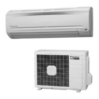
Daikin FTXS25CAVMB Service Manual (246 pages)
Inverter Pair Wall Mounted Type
Brand:
Daikin
| Category:
Air Conditioner
| Size: 13.03 MB
Table of Contents
Table of Contents
3
Introduction
6
Safety Cautions
6
Caution in Repair
6
Cautions Regarding Products after Repair
7
Inspection after Repair
8
Using Icons
9
Using Icons List
9
Part 1 List of Functions
10
List of Functions Part
10
List of Functions
11
High Grade Models
11
Standard Grade Models
14
Non-Lnverter Models
18
Part 2 Specifications
20
Cooling Only
21
Ftks25Cvmb(9)(8)
21
Heat Pump
29
Ftxs35Cvmb(9)(8)
30
Part 3 Printed Circuit Board Connector Wiring Diagram
46
Printed Circuit Board Connector Wiring Diagram
47
Indoor Unit
47
Outdoor Unit / RK(X)S-C, ARK(X)S-C
49
Outdoor Unit / RK(X)H-C, ARK(X)H-C, R(Y)N-C
51
Part 4 Function and Control
52
Main Functions
53
Frequency Principle
53
Power-Airflow Dual Flaps, Wide-Angle Louvres and Auto-Swing
55
Fan Speed Control for Indoor Units
56
Programme Dry Function
57
Automatic Operation
58
NIGHT SET Mode
59
Intelligent Eye
60
HOME LEAVE Operation
62
Inverter POWERFUL Operation
63
Other Functions
64
Function of Main Structural Parts
65
Function of Thermistor
65
Cooling Only Model
66
Control Specification
67
Mode Hierarchy
67
Frequency Control
68
Controls at Mode Changing / Start-Up
70
Discharge Pipe Control
71
Input Current Control
72
Freeze-Up Protection Control
72
Heating Peak-Cut Control
73
Fan Control
73
Liquid Compression Protection Function 2
73
Defrost Control
74
Electronic Expansion Valve Control
75
Malfunctions
78
Forced Operation Mode
79
Additional Function
79
Facility Setting Jumper (Cooling at Low Outdoor Temperature)
80
Part 5 System Configuration
82
System Configuration
83
Instruction
84
Safety Precautions
84
Installation Site
85
Electrical Work
85
Names of Parts
86
Outdoor Unit
87
Remote Control
88
Preparation before Operation
89
Auto Dry Cool Heat Fan Operation
92
Adjusting the Air Flow Direction
94
POWERFUL Operation
96
OUTDOOR UNIT SILENT Operation
97
HOME LEAVE Operation
98
INTELLIGENT EYE Operation
100
TIMER Operation
102
Care and Cleaning
104
Air Filter
105
Before a Long Idle Period
106
Troubleshooting
107
Check Again
108
Part 6 Service Diagnosis
112
Caution for Diagnosis
113
Problem Symptoms and Measures
114
Service Check Function
115
Troubleshooting
118
Error Codes and Description
118
Indoor Unit PCB Abnormality
119
Freeze-Up Protection Control or High Pressure Control
120
Fan Motor (AC Motor) or Related Abnormality
122
Thermistor or Related Abnormality (Indoor Unit)
123
Signal Transmission Error (between Indoor and Outdoor Unit)
124
OL Activation (Compressor Overload)
125
Compressor Lock
126
DC Fan Lock
127
Input over Current Detection
128
Four Way Valve Abnormality
129
Discharge Pipe Temperature Control
131
High Pressure Control in Cooling
132
Position Sensor Abnormality
134
DC Voltage / Current Sensor Abnormality
135
Thermistor or Related Abnormality (Outdoor Unit)
136
Electrical Box Temperature Rise
138
Radiation Fin Temperature Rise
140
Output over Current Detection
142
Insufficient Gas
144
Over-Voltage Detection
146
Check
147
How to Check
147
Four Way Valve Performance Check
148
Thermistor Resistance Check
149
Installation Condition Check
150
Discharge Pressure Check
150
Outdoor Unit Fan System Check
151
Power Supply Waveforms Check
152
Power Transistor Check
153
Hall IC Check
154
Part 7 Removal Procedure
156
Indoor Unit
157
Removal of Air Filter
157
Removal of Front Grille
160
Removal of Horizontal Blade and Vertical Blade
163
Removal of Electrical Box, PCB and Swing Motor
165
Removal of Heat Exchanger
171
Install of Drain Plug
174
Removal of Fan Rotor and Fan Motor
175
Outdoor Unit / RK(X)S-C, ARK(X)S-C
179
Removal of Panels and Fan Motor
179
Removal of Electrical Box
186
Removal of Reactor and Partition Plate
188
Removal of Sound Blanket
190
Removal of Four Way Valve
192
Removal of Compressor
194
Removal of PCB
196
Outdoor Unit / RK(X)H-C, ARK(X)H-C, R(Y)N-C
199
Removal of External Panels
199
Removal of Bell Mouth
202
Removal of PCB and Electrical Box
203
Removal of Propeller Fan and Fan Motor
210
Removal of Partition Plate and Reactor
213
Removal of Sound Insulation Pad
216
Removal of Electronic Expansion Valve and Four Way Valve
219
Removal of Compressor
223
Part 8 Others
226
Others
227
Test Run from the Remote Control
227
Jumper Settings
228
Part 9 Appendix
230
Piping Diagrams
231
Indoor Units
231
Outdoor Units
232
Wiring Diagrams
236
Indoor Units
236
Outdoor Units
237
Index
240
Advertisement
Daikin FTXS25CAVMB Operation Manual (34 pages)
ROOM AIR CONDITIONER
Brand:
Daikin
| Category:
Air Conditioner
| Size: 2.91 MB
Table of Contents
Operation Manual
1
Table of Contents
2
Safety Precautions
3
Installation Site
4
Electrical Work
4
Names of Parts
5
Outdoor Unit
6
Indoor Unit
6
Remote Controller
7
Preparation before Operation
8
Operation
10
AUTO · DRY · COOL · HEAT · FAN Operation
11
To Change the Air Flow Rate Setting
12
Adjusting the Air Flow Direction
13
POWERFUL Operation
15
OUTDOOR UNIT QUIET Operation
16
HOME LEAVE Operation
17
Use as Favorite Mode
18
Use as Energy-Saving Mode
18
INTELLIGENT EYE Operation
19
TIMER Operation
21
To Use on Timer Operation
22
To Combine on Timer and off Timer
22
Note for Multi System
23
Care and Cleaning
25
Air Filter
26
Before a Long Idle Period
27
Trouble Shooting
28
Check Again
29
Call the Service Shop Immediately
30
Disposal Requirements
30
Important Information Regarding the Refrigerant Used
30
Fault Diagnosis
31
Advertisement
Related Products
Daikin FTXS25CVMB
Daikin FTXS25CVMB(9)(8)
Daikin FTXS25CVMB8
Daikin FTXS25CVMB9
DAIKIN Super Multi NX FTXS25G2V1B
DAIKIN FTXS25K2V1B
Daikin FTXS25D3VMW(L)
Daikin FTXS25K
Daikin FTXS25EVMV
Daikin FTXS25KVLT
Daikin Categories
Air Conditioner
Heat Pump
Remote Control
Chiller
Fan
More Daikin Manuals
Login
Sign In
OR
Sign in with Facebook
Sign in with Google
Upload manual
Upload from disk
Upload from URL