Sign In
Upload
Manuals
Brands
Bard Manuals
Air Conditioner
W3SAC-A
Bard W3SAC-A Manuals
Manuals and User Guides for Bard W3SAC-A. We have
2
Bard W3SAC-A manuals available for free PDF download: User Manual, Installation Instructions Manual
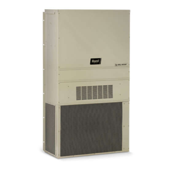
Bard W3SAC-A User Manual (87 pages)
Brand:
Bard
| Category:
Air Conditioner
| Size: 3.2 MB
Table of Contents
Table of Contents
14
General
15
Recovery Equipment Rated for R-410A
15
Leak Detectors
15
Gauge Manifold
15
Attaching Gauge Manifold
15
Attaching Manifold Hose to Schrader Valve
16
Leak Test
16
Evacuation
16
Charging
17
Preliminary Charging Steps
17
Charging the System by Weight
17
Figure 1: Typical AC System Cooling Cycle
18
Figure 2: Typical HP System Cooling Cycle
19
Figure 3 Heating Cycle
20
Troubleshooting the Mechanical System
21
Air Conditioning & Heat Pump - Cooling
21
Low Suction - Low Head Pressure
21
High Suction - Low Head Pressure
21
Low Suction - High Head Pressure
21
High Suction - High Head Pressure
21
Heat Pump - Heating
21
Getting Other Information and Publications
27
Wall Mount General Information
28
Air Conditioner Wall Mount Model Nomenclature
28
Shipping Damage
28
General
28
Duct Work
29
Filters
29
Filter Removal/Installation
29
Switching Filter Sizes
30
Fresh Air Intake
31
Condensate Drain
31
Installation
32
Basic Installation Design and Application Planning
32
Wall Construction
32
Outdoor Area Inspection
32
Condensate Water Drainage
32
Indoor Ducted and Non-Ducted Applications
32
Indoor Supply Airflow
32
Indoor Return Airflow
32
Ducted Applications
32
Free Blow Applications
33
Thermostat or Indoor Temperature Sensor Placement
33
Unit Installation
33
Materials/Tool List
33
Wall Preparation
34
Wall Mount Installation to Wall Surface
34
Table 1 Clearance Required for Service Access and Adequate Condenser Airflow
34
Table 2 Minimum Clearances Required to Combustible Materials
35
Wiring - Main Power
41
High Voltage Connections
41
Wiring - Low Voltage
42
Low Voltage (24VAC) Connections
42
Unit Shutdown Feature
42
Balanced Climate TM Feature
42
Table 3 Additional Low Voltage Connections (if Applicable)
42
Dehumidification Feature
43
Ventilation Features
43
Alarm Relay Feature
43
DDC Controls Feature
43
Dirty Filter Switch Indicator (DFS)
43
Discharge Air Sensor
43
Airflow Switch
43
Compressor Current Sensor
43
Table 4 Low Voltage Connections for DDC Control
43
Table 5A Wall Thermostats - 2 Stage
44
Table 5B Wall Thermostats - 3 Stage
44
Table 6 Humidity Controls
44
Table 7 CO Controllers
44
Table 8 Thermostat Wire Size
44
Start up
47
General
47
Topping off System Charge
47
Safety Practices
47
Important Installer Note
47
Service Hints
47
High Pressure Switch
47
Three Phase Scroll Compressor Start up Information
48
Phase Monitor
48
Condenser Fan Operation
48
Vent Connection Plug
48
Compressor Control Module
48
Features
48
Delay-On-Make Timer
48
Short Cycle/Delay-On-Break
48
Low Pressure Detection
48
High Pressure Detection
49
Test Mode
49
Brownout Protection with Adjustment
49
Pressure Service Ports
50
Sequence of Operation
50
Cooling
50
No Economizer
50
With Economizer
50
Balanced Climate TM Mode
50
Service
52
Troubleshooting Nidec Selectech Series ECM Motors
52
If the Motor Is Running
52
If the Motor Is Not Running
52
Model Selectech Communication Diagnostics
53
Compressor Solenoid
54
Compressor Solenoid Test Procedure
54
Fan Blade Setting Dimensions
54
Table 9 Fan Blade Dimensions
54
Removal of Fan Shroud
55
R-410A Refrigerant Charge
55
Table 10A 2Nd Stage Cooling Pressures - Standard Airflow
56
Table 10B 1St Stage Cooling Pressures - Balanced Climate Airflow
56
Table 11 Electrical Specifications
57
Setting Unit Airflow
58
Blower Speeds
58
Table 12 Recommended Airflow
58
Table 13 Blower Speeds for Unit Operational Modes
58
Speed Tap 1 - Vent/Blower Only
59
Speed Tap 2 - Balanced Climate
59
Speed Tap 3 - Default lo Cooling
59
Heating
59
Speed Tap 4 - Optional MED Cooling
59
Speed Tap 5 - Optional HI Cooling
59
Dirty Filter Switch
59
Dirty Filter Switch Adjustment
59
Table 14 Indoor Blower Performance
62
Table 15 Maximum ESP Electric Heat Only
63
Table 16 Electric Heat
63
Table 17 Vent and Control Options
63
Table 18 Optional Accessories
64
Advertisement
Bard W3SAC-A Installation Instructions Manual (42 pages)
11EER Step Capacity 2 Stage Wall Mount Air Conditioner
Brand:
Bard
| Category:
Air Conditioner
| Size: 1.85 MB
Table of Contents
Table of Contents
2
Getting Other Information and Publications
3
Wall Mount General Information
4
Air Conditioner Wall Mount Model Nomenclature
4
Shipping Damage
4
General
4
Duct Work
5
Filters
5
Filter Removal/Installation
5
Figure 1 Front Control Panel Cover
5
Figure 2 Removing Left Filter
5
Switching Filter Sizes
6
Figure 3 Removing Second Filter
6
Figure 4 Filter Tabs in up Position
6
Figure 5 Bend Filter Tabs down
6
Figure 6 Remove Four Screws
6
Figure 7 Re-Install Filter Support Brackets into Lower Slots
6
Figure 8 Re-Install Screws and Bend Tabs up
6
Fresh Air Intake
7
Condensate Drain
7
Figure 9 Install Right 2" Filter
7
Figure 10 Install Left 2" Filter
7
Figure 11 Fresh Air Damper
7
Installation
8
Basic Installation Design and Application Planning
8
Wall Construction
8
Outdoor Area Inspection
8
Condensate Water Drainage
8
Indoor Ducted and Non-Ducted Applications
8
Indoor Supply Airflow
8
Indoor Return Airflow
8
Ducted Applications
8
Free Blow Applications
9
Thermostat or Indoor Temperature Sensor Placement
9
Unit Installation
9
Materials/Tool List
9
Wall Preparation
10
Wall Mount Installation to Wall Surface
10
Figure 12 Vent Installation/Removal Clearance Required
11
Table 1 Clearance Required for Service Access and Adequate Condenser Airflow
11
Table 2 Minimum Clearances Required to Combustible Materials
11
Figure 13 Unit Dimensions
12
Figure 14 Mounting Instructions
13
Figure 15 Electric Heat Clearance
14
Figure 16 Wall Mounting Instructions
15
Figure 17 Wall Mounting Instructions
15
Figure 18 Common Wall Mounting Installations
16
Wiring - Main Power
17
High Voltage Connections
17
Figure 19 High Voltage Connections
17
Wiring - Low Voltage
18
Low Voltage (24VAC) Connections
18
Unit Shutdown Feature
18
Balanced Climate TM Feature
18
Table 3 Additional Low Voltage Connections (if Applicable)
18
Dehumidification Feature
19
Ventilation Features
19
Alarm Relay Feature
19
DDC Controls Feature
19
Dirty Filter Switch Indicator (DFS)
19
Discharge Air Sensor
19
Airflow Switch
19
Compressor Current Sensor
19
Table 4 Low Voltage Connections for DDC Control
19
Table 5A Wall Thermostats - 2 Stage
20
Table 5B Wall Thermostats - 3 Stage
20
Table 6 Humidity Controls
20
Table 7 CO 2 Controllers
20
Table 8 Thermostat Wire Size
20
Figure 20 Programmable Thermostat Connections
21
Figure 21 Non-Programmable Thermostat Connections
22
Start up
23
General
23
Topping off System Charge
23
Safety Practices
23
Important Installer Note
23
Service Hints
23
High Pressure Switch
23
Three Phase Scroll Compressor Start up Information
24
Phase Monitor
24
Condenser Fan Operation
24
Vent Connection Plug
24
Compressor Control Module
24
Features
24
Delay-On-Make Timer
24
Short Cycle/Delay-On-Break
24
Low Pressure Detection
24
High Pressure Detection
25
Test Mode
25
Brownout Protection with Adjustment
25
Figure 22 8201-169 Compressor Control Module
25
Pressure Service Ports
26
Sequence of Operation
26
Cooling
26
No Economizer
26
With Economizer
26
Balanced Climate TM Mode
26
Service
28
Troubleshooting Nidec Selectech Series ECM Motors
28
If the Motor Is Running
28
If the Motor Is Not Running
28
Figure 23 Motor Connections
28
Model Selectech Communication Diagnostics
29
Figure 24 Motor Connections
29
Compressor Solenoid
30
Compressor Solenoid Test Procedure
30
Fan Blade Setting Dimensions
30
Figure 25 Fan Blade Setting
30
Table 9 Fan Blade Dimensions
30
Removal of Fan Shroud
31
R-410A Refrigerant Charge
31
Figure 26 Fan Shroud Removal
31
Table 10A 2Nd Stage Cooling Pressures - Standard Airflow
32
Table 10B 1St Stage Cooling Pressures - Balanced Climate Airflow
32
Table 11 Electrical Specifications
33
Setting Unit Airflow
34
Blower Speeds
34
Figure 27 Speed Taps
34
Table 12 Recommended Airflow
34
Table 13 Blower Speeds for Unit Operational Modes
34
Speed Tap 1 - Vent/Blower Only
35
Speed Tap 2 - Balanced Climate
35
Speed Tap 3 - Default lo Cooling
35
Heating
35
Speed Tap 4 - Optional MED Cooling
35
Speed Tap 5 - Optional HI Cooling
35
Dirty Filter Switch
35
Dirty Filter Switch Adjustment
35
Figure 28 Speed Taps
35
Figure 29 Dirty Filter Switch and Dirty Filter Indicator Light/Reset Switch
36
Figure 30 Adjusting Filter Switch
37
Table 14 Indoor Blower Performance
38
Table 15 Maximum ESP Electric Heat Only
39
Table 16 Electric Heat
39
Table 17 Vent and Control Options
39
Table 18 Optional Accessories
40
Advertisement
Related Products
Bard W3SAC-B
Bard W3SAC-C
Bard W3SACDA
Bard W3SACDB
Bard W3SACDC
Bard W36A1-C
Bard W38A1-B
Bard W30ABDC Series
Bard MULTI-TEC W36LAPB09
Bard W36L2-C
Bard Categories
Air Conditioner
Heat Pump
Medical Equipment
Furnace
Controller
More Bard Manuals
Login
Sign In
OR
Sign in with Facebook
Sign in with Google
Upload manual
Upload from disk
Upload from URL