Sign In
Upload
Manuals
Brands
Alcatel Manuals
Network Router
7750 SR-12
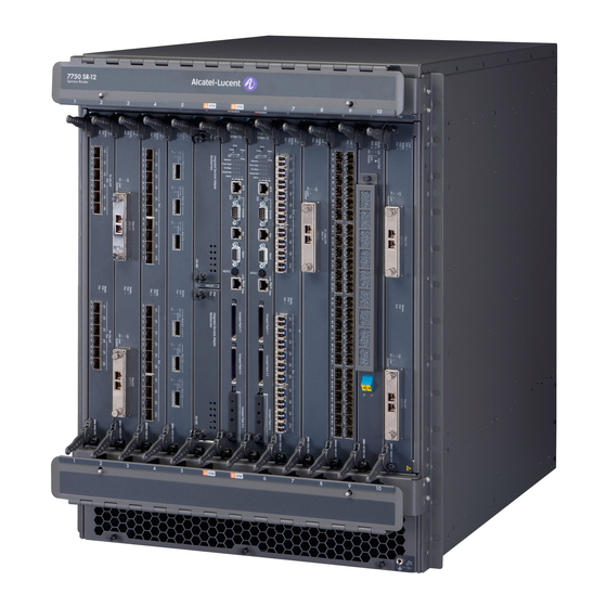
Alcatel 7750 SR-12 Manuals
Manuals and User Guides for Alcatel 7750 SR-12. We have
1
Alcatel 7750 SR-12 manual available for free PDF download: Installation Manual
Alcatel 7750 SR-12 Installation Manual (158 pages)
Brand:
Alcatel
| Category:
Network Router
| Size: 3.39 MB
Table of Contents
Table of Contents
3
Preface
11
Preface
12
Table 1: Information Symbols
12
7750 SR-12 Overview
15
Chassis Features
16
7750 SR-12 Overview
17
Figure 1: 7750 SR-12 Chassis Front View
17
Table 2: Chassis Front View Features
18
7750 SR-12 Overview
19
Figure 2: 7750 SR-12 Chassis Rear View
19
Table 3: Chassis Rear View Features
20
7750 SR-12 Modules
21
Sf/Cpms
21
Figure 3: SF/CPM Faceplate Example
21
Table 4: Model SFM-400G SF/CPM Field Descriptions
22
Synchronization in Redundant Systems
26
Ioms
27
Mdas
27
Chassis Components
28
Power Supplies
28
Table 5: DC Power Entry Module Features
29
Figure 4: SR-12 DC Power Entry Module
29
DC Power Entry Modules
29
Figure 5: 7750 SR-12 AC Power Rectifier (Example)
30
AC Power Supply Modules
30
Cooling System
31
Table 6: AC Power Rectifier Features
31
Air Filter
32
Blank Panels
32
Cable Management System
32
Component Operating Requirements
33
Table 7: 7750 SR-12 Hardware Component Operating Requirements Summary
33
7750 SR-12 System Installation Process
34
Site Preparation
35
Warnings and Notes
36
System Specifications
37
Chassis Specifications
37
Environmental Specifications
37
Table 8: Chassis Specifications
37
Table 9: Environmental Specifications
37
Site Preparation
37
Power Module Specifications
38
Table 10: Power Module Specifications
38
Table 11: Electrical Characteristics
38
MDA Specifications
39
Site Preparation
39
Table 12: MDA Specifications
39
Component Power Consumption
40
Table 13: Power Consumption
40
Component Specifications
41
Table 14: Component Specifications
41
The Equipment Rack
42
Rack Clearance Requirements
43
Figure 6: Chassis Clearance Requirements
43
Safety Considerations
44
Grounding
44
Power
44
Fans
45
Air Filter
45
Storage
45
Table 15: Storage Specifications
45
Safety Standards/Compliance Agency Certifications
46
Table 16: Safety Standards and Compliance Agency Certifications
46
Installing the 7750
47
Unpacking the Chassis
48
Unpacking Precautions
48
Installing the 7750
49
Figure 7: Unfastening the Crate Clips
49
Figure 8: Opening the Crate
50
Figure 9: Removing the Chassis from the Crate
51
Figure 10: Lifting the Chassis
52
Rack Mounting the Chassis
53
Installing the 7750 SR-12
54
Table 17: Rack Mounting the 7750 SR-12 Chassis
54
Figure 11: Installing the Chassis into an Equipment Rack
54
Installing the Cable Management System
56
Figure 12: Cable Management System
57
Making the Chassis Ground Connection
58
Preparing the Ground Wire
58
Table 18: Ground Wire Descriptions
58
Figure 13: Preparing the Ground Wire
58
Making the Ground Wire Connection
60
Table 19: Ground Wire Descriptions
60
Figure 14: Connecting the Grounding Lug
60
Installing Impeller Trays
62
Warnings and Notes
62
Table 20: Impeller Tray Descriptions
63
Figure 15: Installing Impeller Trays
63
7750
63
Installing Power Supplies
65
Installing Power Supplies
66
General Power Warnings and Notes
66
Installing DC Pems
67
DC Power Warnings and Notes
67
Installing Adc Pem
69
Table 21: Installing a DC PEM
69
Figure 16: Installing a DC PEM
69
DC-Input Power Wiring
71
Preparing the Power Cable
71
Figure 17: DC Terminal Block Stud Dimensions and Spacing
71
Figure 18: DC Terminal Block Lug
71
Table 22: DC Power Cable
72
Figure 19: Preparing the DC Cable
72
DC Input Terminal Block Wiring
73
Figure 20: Removing the DC Terminal Block Safety Cover
73
Figure 21: Wiring the DC-Input Power Terminal Block
73
Figure 22: DC-Input Power Terminal Block Wiring with Safety Cover
74
Table 23: DC-Input Terminal Block Descriptions
75
Figure 23: Installed DC Power Entry Modules
75
AC-Input Power Guidelines
76
AC Power Warnings and Notes
76
Installing Power Supplies
69
Installing an AC Power Shelf
78
Installing the AC Power Rectifiers
79
Connecting the AC Power Shelf Cables to the DC Pems
79
Table 24: AC Power Shelf to DC PEM Cabling Features
80
Figure 24: Connecting the Cables
80
Installing the SF/CPM
81
Figure 25: DC Terminal Block
81
Monitoring AC Power
82
Figure 26: Status Cable Connections
82
Installing the SF/CPM
85
Installing SF/CPM Modules
86
Warnings and Notes
86
Installing the SF/CPM
87
Table 25: Installing SF/CPM Features
88
Figure 27: Installing the SF/CPM Module
88
Initializing the System
90
Using the Compact Flash Slot #3 Locking Mechanism
91
Figure 28: Compact Flash Slot #3 on the SF/CPM Front Panel
91
Initial System Startup
92
Troubleshooting
92
Figure 29: Files on the Compact Flash
94
Establishing Router Connections
95
Console Connection
95
Table 26: Console Configuration Parameter Values
95
Figure 30: Console Port Connection
96
Telnet Connection
97
Figure 31: Management Port Connection
97
Ejecting Flash Cards
99
Installing the Ioms and Mdas
101
Configuring Chassis Slot, IOM, and MDA Parameters
102
Configuring Chassis Slot and IOM Parameters
102
Configuring MDA Parameters
103
Example
103
Installing the Ioms and Mdas
103
Installing Ioms
105
Warnings and Notes
105
Installing the Ioms and Mdas
105
Installing Ioms
106
Figure 32: Installing an IOM
106
Installing Mdas
108
Warnings and Notes
108
Installing an MDA on an IOM
109
Table 27: MDA Installation Features
109
Figure 33: Installing an MDA on an IOM
109
Installing an MDA on a Chassis-Installed IOM
111
Figure 34: Installing an MDA on an IOM in the Chassis
111
Removing Blank Panels
112
Figure 35: Removing Blank Panels
112
Appendix A: Leds
113
Appendix A: Leds
114
AC Power Supply Module Leds
114
Table 28: 7750 SR-12 AC Power Supply LED Descriptions
114
Figure 36: Example of AC Power Supply Leds
114
Power Supply Leds on the CPM Front Panel
115
Table 29: Model SFM-400G SF/CPM Field Descriptions
115
Appendix A: Leds
115
Figure 37: Power Supply Leds
115
SF/CPM Leds
116
Table 30: Model SFM-400G SF/CPM Field Descriptions
116
Figure 38: SF/CPM Front Panel
116
Appendix B: Field Replaceable Units
121
Air Filter Tray
122
Removing the Air Filter Tray
122
Figure 39: Removing the Air Filter Tray
122
Table 31: Filter Tray Features
123
Replacing the Air Filter Tray
124
Figure 40: Replacing the Air Filter Tray
124
Appendix B: Field Replaceable Units
123
Sf/Cpms
125
Warnings and Notes
125
Removing an SF/CPM
126
Figure 41: Removing an SF/CPM Module
126
Replacing an SF/CPM
127
Figure 42: Replacing the SF/CPM Module
127
Ioms
129
Warnings and Notes
129
Shutting down and Modifying Card Configuration
130
Installing a Different IOM Type
131
Appendix B: Field Replaceable Units
131
Installing a Filler Panel Blank
133
Removing an IOM
133
Figure 43: Replacing an IOM
134
Replacing an IOM
134
Mdas
135
Warnings and Notes
135
Changing the MDA Configuration
136
Removing an MDA
137
Figure 44: Removing an MDA
137
Replacing an MDA
138
Figure 45: Replacing an MDA
138
Power Modules
139
Warnings and Notes
139
Removing a DC PEM
141
Figure 46: Removing a DC PEM
141
Replacing Adc Pem
143
Figure 47: Replacing a DC PEM
143
AC Power Shelves and Rectifiers
145
Disconnecting AC Power Cables
145
Figure 48: Disconnecting AC Power Cables
146
Impeller Trays
147
Warnings and Notes
147
Removing an Impeller Tray
148
Figure 49: Removing an Impeller Tray
148
Replacing the Impeller Tray
149
Figure 50: Replacing the Impeller Tray
149
Appendix C: Pinout Assignments
151
SF/CPM Port Types
152
Figure 51: Port Types
152
Appendix C: Pinout Assignments
153
Cable Pin Assignments
153
Table 32: BITS Port - RJ48C Female
153
Table 33: Console Port - DTE Mode - DB9 Male
153
Appendix C: Pinout Assignments
153
Table 34: Console Port - DCE Mode - DB9 Male
154
Table 35: Auxiliary Port - DTE Mode Only - DB9 Male
154
Table 36: Alarm Port - DB9 Female
155
Table 37: 10/100 Management Ethernet Port - RJ45 Female
155
Index
157
Advertisement
Advertisement
Related Products
Alcatel SPEEDTOUCH 710
Alcatel 7710 SR OS
Alcatel 7750 SR-7
Alcatel OmniSwitch 7700
Alcatel OT-V 770A
Alcatel ONETOUCH POP 7S P330X
Alcatel ONETOUCH 7048A
Alcatel OmniSwitch 7000
Alcatel 7053J
Alcatel Viper 7030Y
Alcatel Categories
Cell Phone
Telephone
Tablet
IP Phone
Switch
More Alcatel Manuals
Login
Sign In
OR
Sign in with Facebook
Sign in with Google
Upload manual
Upload from disk
Upload from URL