
Related Manuals for Husqvarna WR 250 2013


Summary of Contents for Husqvarna WR 250 2013
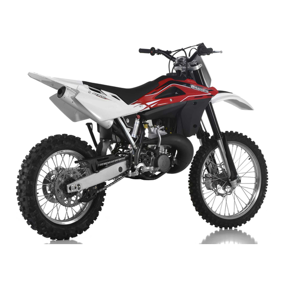
- Page 1 WR 250 - WR 250 USA 2013 WR 300 - WR 300 USA 2013 Manuale utente_Owner’s manual_Manuel d’utilisateur_Benutzerhandbuch_Manual del usuario...
- Page 2 WR 250 WR 300 WR 250 - WR 250 USA 2013 WR 300 - WR 300 USA 2013 SPECIFICATIONS - OPERATION - MAINTENANCE EN- 1 Ed. 05-2012 - Rev. 00 Unless specified, data and prescription are referred to all the models.
-
Page 3: Table Of Contents
TABLE OF CONTENTS Note Page • References to the “left” or “right” of the motorcycle are in the sense of a person facing forwards. PRESENTATION ............... 3 IMPORTANT NOTICES .............. 3 • number of teeth IDENTIFICATION DATA ............. 5 • Austria CONTROl lOCATION ..............6 AUS:... -
Page 4: Presentation
Appendix A. tention of a skilled mechanic and the use of special tools and equipment. WR 300 Your Husqvarna dealer has the facilities, experience and origi- nal parts necessary to properly render this valuable service. This “Owner’s Manual” is part and par- cel of the motorcycle, hence, this had to remain with the motorcycle even when sold to another user. - Page 5 WARNING*: Do not attempt to start or ride cause severe damage to the engine. Parts Replacement this motorcycle until you have received expert This motorcycles was not designed for urban When parts replacement is required, use only Husqvarna ORIGI- instruction and are in excellent physical condi- use and is not equiped with a cooling fan and tion. NAl parts. thermostat. Long stops at the traffic lights can cause overheating and the boiling of radiator water. This motorcycles is setup for...
-
Page 6: Identification Data
IDENTIFICATION DATA The engine number is printed on the upper side of the engi- ne case, whereas the frame number is printed on the steering tube. Always state the number stamped on the frame (and write it on this booklet), when placing orders for spare parts, or when asking for information on your motorcycle. FRAME NUMBER VEHIClE IDENTIFICATION NUMBER (V.I.N.) The full 17 digit serial, or Vehicle Identification Number, is... -
Page 7: Control Location
CONTROL LOCATION 1. Front brake lever 2. Throttle grip 3. l.H. commutator 4. Rear brake control pedal 5. Starting pedal 6. Clutch control lever 7. Fuel tank filler cap 8. Gearbox control pedal 9. Choke (l.H. side) 10. Fuel cock EN - 6 SPECIFICATIONS - OPERATION - MAINTENANCE... -
Page 8: Technical Data
TECHNICAL DATA FUEl SYSTEM FINAl RATIOS Type........... Carburettor “Mikuni” TMX 38 ENGINE 1st gear ................20,220 Venturi diameter ...........1.49 in. (38 mm) 2nd gear ...............16,513 Type single cylinder, 2 stroke ..........3rd gear ...............13,564 High speed jet ..............380 Cooling liquid ................. 4th gear ................11,422 Bore High speed jet (250 USA) ...........430 (250) ..........2.61 in (66,4 mm) - Page 9 RIMS TABLE FOR LUBRICATION, SUPPLIES Front ............. in light alloy: 1,6x21” Rear.............in light alloy: 2,15x18” Engine lubricating oil CASTROl A747 TYRES Front ..............90/90x21” Gearbox and primary drive lubricating oil Rear..............140/80x18” CASTROl POWER 1 RACING 10W-40 Cold tire pressure Engine coolant (front) (*)............12.8÷14.2 psi CASTROl MOTORCYClE COOlANT ( front) (%) ..............15.6 psi rider and passenger...
-
Page 10: Controls
CONTROLS A fuel filter is incorporated in the fuel valves. Accumulation of SIDESTAND dirt in the filter will restrict the flow of the fuel to the carburetor. A sidestand (1) is supplied with every motorcycle. FUEl SUPPlY VAlVES Therefore, the fuel filter should be serviced periodically. To service: WARNING*: The stand is designed to sup- The cock (1) set on left side of tank has three positions:... - Page 11 FUEl CARBURETOR CHOKE The motorcycle is equipped with 2 stroke engine that requires The starter knob (1), located on the left side of the carburetor, is a gasoline-oil mixture. Recommended fuel: premium grade un- used to enrich the mixture during the engine start. leaded fuel (R.O.N.
- Page 12 DIGITAL INSTRUMENT, WARNING LIGHTS - The instrument functions are the following, as shown below. 1- SPEED (Km/h or mph) / ODO The motorcycle is equipped with a digital instrument; on the 1- SPEED / ODO - SPEED: motorcycle speed- maximum value: 299 Km/h or 299 instrument are located 2 warning lights too: high beam and 2- SPEED / ClOCK mph;...
- Page 13 2- SPEED / ClOCK 3- SPEED / TRIP 1 4- SPEED / CHRONO (STP) - SPEED: motorcycle speedmaximum value: 299 Km/h o 299 - SPEED: motorcycle speedmaximum value: 299 Km/h o 299 - SPEED: motorcycle speedmaximum value: 299 Km/h o 299 mph;...
- Page 14 THROTTLE CONTROL STEERING LOCK The throttle knob (1), is located on the right hand side of the The motorcycle is equipped with a steering lock (1) on the R.H. handlebar. The position of the throttle control can be adjusted side of the steering head tube. by loosening the two fastenig screws .
- Page 15 HANDLEBAR COMMUTATOR CLUTCH CONTROL The clutch lever is located on the left-hand side of the handlebar 1) Engine stop button ( and is protected against dirt filtering in. The lever support is pro- vided with adjusting screw (1) to regulate clutch wire free play. 2) HI = ( ) Selection control High beam The clutch lever can be adjusted to suit your driving position.
- Page 16 REAR BRAKE CONTROL GEAR SHIFT CONTROL KICKSTART PEDAL The kickstart pedal (1) is situated on the right-hand side of the The rear brake control (1) is placed on the right-hand side of the The lever (1) is placed on the left-hand side of the engine. The motorcycle.
-
Page 17: Riding
RIDING 9. Check torque avoid hard accelerations. A. Spark plug. 6.Repeat cool down procedure. BEFORE EVERY RIDE MAKE FOllOWING CHECKS B. General check of torque 7. Full throttle operation must be avoided until the engine has WARNING! 10. Check steering action reached operating temperature, even after the break in process Before each ride, to prevent accidents or failures during ride, Check bearing play. - Page 18 IMPORTANT NOTE IN CASE OF COLD STARTS ENGINE START IMPORTANT AT LOW TEMPERATURES Never accelerate the engine after a cold start. For the correct start of a cold engine proceed as follows: It is recommended to briefly warm-up - shift the transmission into neutral; the engine at idle until, after having dis- - set fuel valve (1) in ON position; WARNING*: Exhaust contains poisonous car- engaged the starter, there is a normal - lift the knob lever (3) on the carburetor.
- Page 19 STOPPING THE MOTORCYCLE AND THE ENGINE - Press the engine stop button (3). - Close the fuel cock (4). When the bike is off, place it on its side stand. - Close the throttle (1) completely so that the engine will help slow down the motorcycle. - For normal braking, gradually apply both front and rear brakes while down shifting (for maximum deceleration, apply the front and rear brakes firmly).
- Page 20 TRANSMISSION OIL LEVEL CHECKING TRANSMISSION OIL CHANGE COOLANT LEVEL CHECK Check level (1) in right-hand radiator when engine is cold (place By keeping the motorcycle on a flat surface and in vertical position, To completely replace the oil, unscrew the plug (A) under the the motorcycle so that it is perpendicular to the ground). The remove the control screw (C), and check the level through the hole oil sump and let oil come out, then screw the plug again with its coolant should be approximately 10 mm above cells.
- Page 21 REPLACEMENT OF COOLING FLUID WARNING*: Coolant on tires will make them slippery and can cause an accident or injury. The cooling liquid replacement must be performed with cold motor, as follows: Periodically check the connecting hoses (see “Periodical mainte- - remove the R.H. radiator plug; nance card”): this will avoid coolant leakages and consequent - remove the drain screw (2) on the pump cover or the pump engine seizure: If hoses show cracks, swelling or hardenings due cover by loosening the two screws (1);...
- Page 22 THROTTLE CABLE ADJUSTMENT - if register (2) should not provide sufficient movement to allow IDLING ADJUSTMENT for correct adjustment, then adjust register placed on carbu- The throttle cable can be adjusted using the screw set on the retor. Idling should be adjusted only when the engine is hot and throt- throttle, or using the adjusting screw set on the There should be approx.
- Page 23 CLUTCH ADJUSTMENT The adjustment can be also effected with tightener (1) set on the right of the frame. Take care to tighten properly the lock nut. If The clutch is adjusted by stretching the cable using the adjusting the clutch slips under load or drags in disengaged position after unit positioned on the handlebar.
- Page 24 SPARK PLUG CHECK Correct heat rating: Before refitting the plug, thoroughly cle- The tip of the insulator should be dry and the colour should be light an the electrodes and the insulator using a Use NGK BR8EG spark plug (2); the gap is 0,6÷0,7 in. brown or grey.
- Page 25 AIR FILTER CHECK AIR FILTER AND CLEANING ASSEMBLY Turn rear pin (1) counterclockwise, remove the saddle from the Wash the filter with a specific detergent (CASTROl FOAM AIR To ensure tight fit, slightly (C) grease filter edge on side facing front afstening screw. FIlTER ClEANER or similar) then dry it fully (wash filter with filter housing.
- Page 26 STEERING WHEEL BALL PLAY ADJUSTMENT Stand in front of the motorcycle and grasp the lower end of the fork rods sliders moving them in the direction of their axis. To ensure maximum safety, the steering wheel should always be Se si avverte gioco occorrerà eseguire la regolazione operando regulated so that the handlebars steering the motorcycle rotate come segue: freely without play.
- Page 27 (1), which can be checked from the window the motorcycle under such conditions, have contact, flush thoroughly with water and call on the rear side of the pump body. the brake checked immediately by an a doctor if your eyes were exposed. authorized HUSQVARNA dealer. A: to encrease clearance B: to decrease clearance EN - 26 SPECIFICATIONS - OPERATION - MAINTENANCE...
- Page 28 REAR BRAKE PEDAL POSITION ADJUSTMENT REAR BRAKE IDLE STROKE ADJUSTMENT CHECKING THE FLUID LEVEL The position of the rear foot brake pedal as to the footrest may The rear brake foot pedal should have a (B) 5 mm (0.2 in.) idle The level (A) must be set between the pump tank notches. be adjusted according to the individual needs.
- Page 29 ADJUSTING THE SUSPENSIONS ACCORDING TO SANDY GROUND NOTE: PARTICULAR TRACK CONDITIONS Fork: have a harder compression adjustment, or replace the When the fork results as either too soft or too hard for any ad- standard spring with a harder one, and make a softer compres- justment conditions, check the oil level inside the forkrod.
- Page 30 The standard calibrations and the adjustment procedures are c) AIR VENT (to carry out after each competition, or monthly). OIL FORK LEVEL shown below. Set the motorcycle on a central stand and release the fork fully For the regular fork operation, both legs must be provided with and loosen the air vent valve (D).
- Page 31 ADJUSTING THE SHOCK ABSORBER 4. The difference between these two measurements constitutes ADJUSTING THE SHOCK ABSORBER SPRING PRE- LOAD the “SAG” of the motorcycle’s rear end. The rear shock absorber must be adjusted according to the rider Suggested SAG: 4 in. with cold shock absorber. 3.7 in. with Proceed as follows: weight and track conditions.
- Page 32 2. Clean ringnut (1) and adjusting nut (2) of the spring (3). B) EXTENSION - Standard calibration: SHOCK ABSORBER DAMPING ADJUSTMENT 3. Either with a hook wrench or an aluminium punch, loosen - 15 clicks (± 2 clicks) Adjustment of the compression stroke is independent from the the ringnut.
- Page 33 CHAIN ADJUSTMENT (Fig. A) Fast adjustment (Fig. B.) CHECKING THE WEAR OF CHAIN, PINION AND SPROCKET Chain should be checked, adjusted and lubricated as per the Push the chain towards the final part of runner and check that Check the pinion damages or wear and replace it should the Maintenance Chart to ensure security and prevent excessive between the two elements a distance “A”...
- Page 34 LUBRICATING THE CHAIN Washing the chain with OR 6- Correctly adjust chain, as described in the relevant para- lubricate the chain following these instructions. Wash using oil, diesel oil, or paraffin oil. Never use gasoline, graph. tricloroetilene, or solvents, as the OR may suffer damages. WARNING: The chain oil has NEVER to get in WARNING * : Never use grease to lubricate Use instead special sprays for chains with OR.
- Page 35 REMOVING THE FRONT WHEEL NOTES Do not operate the front brake lever when the wheel has been Set a stand or a block under the engine and see that the front removed; this causes the caliper piston to move outwards. After wheel is lifted from the ground. loosen the bolts (1) holding the removal, lay down the wheel with brake disc on top.
- Page 36 REASSEMBLING THE FRONT WHEEL Fit the wheel axle (2) from the R.H. side, after greasing it and NOTE push it to the stop on the l.H. leg; during this operation, the After reassembly, pump the brake control lever until the pads Fit the l.H. spacer (A) on the wheel hub. are against the brake disc.
-
Page 37: Removing The Rear Wheel
Removing the ReaR wheel noteS Do not operate the rear brake pedal when the wheel has been Unscrew the nut (1) of the wheel pin (3) and extract it. It is removed; this causes the caliper piston to move outwards. not necessary to unloose the chain adjusters (2);... - Page 38 TIRES BRAKES 4. Front brake caliper 5. Front brake disc Care should be taken to keep the tyres properly inflated. See The mayor components are brake master cylinder with its lever 6. Rear brake oil tank “Technical data” chart at the beginning of the manual for cor- (front) or pedal (rear), brakeline, caliper assembly and disc.
- Page 39 BRAKE PADS REMOVAL PADS WEAR Inspect pads for wear. - Remove springs (1). Service limit “ A” is: 3,8 mm (0.15 in.). - Remove pins (2). If service limit is exceeded, always replace the pads in pairs. - Remove pads. CAUTION! Don’t operate the brake lever or pedal while removing the pads.
- Page 40 PADS CLEANING WARNING! Do not attempt to ride the motorcycle until Be careful that no disc brake fluid or any oil gets on brake pads the brake lever or pedal are fully effective. or discs. Clean off any fluid or oil that inadverently gets on the Pump the brake lever or pedal until the pads pads or disc with alcohol. are against the discs.
- Page 41 BRAKE DISC WEAR DISC WARPAGE Measure disc warpage. Service limit for both discs is 0,15 mm Measure the thickness of each disc at the point where it has worn (0.006 in.) the most. Replace the disc if it has worn past the service limit. Replace the disc if warpage is more than service limit.
- Page 42 DISC CLEANING Poor braking can also be caused by oil on the disc. Oil or grease on the disc must be cleaned off with a high flash-point oil free solvent, such as acetone or lacquer thinner. SPECIFICATIONS - OPERATION - MAINTENANCE EN- 41...
- Page 43 HEADLAMP BULBS REPLACEMENT - remove the two filaments bulb connector (2) and the boot To gain access to the healamp bulbs, proceede as follows: (3); - remove the upper fastening screw of the the headlamp carrier to - release the bulb holder clips (4) and take out bulb (5); the instrument panuel support (1);...
- Page 44 TAIL LIGHT REPLACING THE NUMBER PLATE BULB The tail light (1) is a lED light; Replace it when it does not func- - loosen screw (1) and remove the number plate bulb (2) from tion. the mudguard; - take bulb holder (3) and bulb (4) out of the support; - pull the bulb (4) to detach it from bulb holder.
- Page 45 ADJUSTMENT OF HEADLIGHT Adjust the preadlamp aiming by turning screw (1) to lower or lift the high beam. When checking the proper orienting of headlight, inflate tires at right pressure, sat a person on the saddle and place the mo- torcycle perpendicular with its longitudinal axis 10 meter (33 ft) from a wall or screen.
-
Page 46: Appendix
APPENDIX - Run the engine for about 5 minutes to warm the oil then drain the oil. AFTER-RACE CHECK POINTS - Put in fresh transmission oil. After racing, first clean the motorcycle and then inspect the - Check all the points listed under the inspection and Adjustment entire motorcycle, with special attention to the items listed in Section (Appendix A). - Page 47 It is necessary ABSOLUTELY TO AVOID THAT After washing: After each cleaning, it is recommended the use of a water-repellent product suitable for HIGH PRESSURE JETS OF WATER OR AIR come - lubricate the points listed in the Maintenance Table (Appendix A). to contact with THE ELECTRICAL PARTS, espe- electrical contacts (see table for lubrications - Start the engine and run it for 5 minutes. cially the electronic control unit (1) and the - Test the brakes before riding the motorcycle.
-
Page 48: Pre-Delivery Inspection
Trasmissioni e com. fless. Controllo / Regolazione � Collaudo generale � Catena di trasmissione Controllo / Regolazione � PRE-DELIVERY INSPECTION PRE -DELIVERY INSPECTION Description Operation Pre-delivery Description Operation Pre-delivery Engine oil Check level Tyres Check pressure � � Two-stroke mix oil level Check level �... - Page 49 ALPHABETIC INDEX Reassembling the front wheel ............35 Page Engine start ...................17 Removing the front wheel ..............34 Engine stop button (USA) ...............14 Removing the rear wheel ...............36 Adjusting the compression fork ............29 Replacement of cooling fluid ............20 Adjusting the shock absorber ............30 Replacing the number plate bulb ...........43 Adjusting the shock absorber spring preload ........30 Fuel ....................10...