Table of Contents
Advertisement
Quick Links
Advertisement
Chapters
Table of Contents

Related Manuals for Husqvarna WRE 125 2011


Summary of Contents for Husqvarna WRE 125 2011
- Page 1 Workshop Manual WRE 125 2011 SMS 125 2011 Ed. 05-2011...
- Page 2 HUSQVARNA MOTORCYCLES S.R.L. - Varese disclaims all liabilities for any errors or omissions in this manual and reserves the right to make changes to reflect on-going product development. Illustrations in the manual may differ from actual components. No reproduction in full or in part without written authorisation.
-
Page 3: Foreword, Table Of Contents
FOREWORD, TABLE OF CONTENTS Workshop Manual TE 250 - 310 2011 I.E. WRE 125 2011 SMS 125 2011 Copyright by HUSQVARNA MOTORCYCLES S.R.L. BMW Group Technical Service Via Nino Bixio, 8 21024 (Varese) - Italy tel. ++39 0332 75.61.11 tel. ++39 0332 756 558 www.husqvarna-motorcycles.com... - Page 4 FOREWORD, TABLE OF CONTENTS Foreword This publication is designed for use by HUSQVARNA Service Centres to assist authorised personnel in the maintenance and repair of the models covered in this manual. The technical information provided in this manual is a critical comple- ment to operator training and operators should become thoroughly familiar with it.
-
Page 5: Table Of Contents
FOREWORD, TABLE OF CONTENTS Table of Contents Title Section Foreword, Table of Contents ................a Important Notices ....................b General Information .....................A Maintenance ......................B Troubleshooting ....................C Settings and Adjustments ................... D General Procedures ....................E Engine Disassembly ....................F Engine Overhaul ....................G Engine Assembly .................... -
Page 7: Important Notices
IMPORTANT NOTICES Section Ed. 05-2011... - Page 8 * In order to maintain the vehicle’s “Guarantee of Functionality”, the client must follow the maintenance programme indicated in Section B by having the required maintenance inspections carried out at authorised HUSQVARNA dealers. The cost for changing parts and for the labour necessary in order to comply with the maintenance plan is charged to the Client.
-
Page 9: General Information
GENERAL INFORMATION Section Ed. 05-2011... - Page 10 GENERAL INFORMATION ENGINE ......................A.3 Starting ......................A.3 TIMING SYSTEM ..................A.3 LUBRICATION ....................A.3 IGNITION ......................A.3 FUEL SYSTEM .....................A.3 PRIMARY DRIVE ..................A.3 CLUTCH .......................A.3 TRANSMISSION ..................A.3 Transmission ratio ..................A.3 SECONDARY DRIVE (WRE) ...............A.4 SECONDARY DRIVE (SMS) ................A.4 FINAL RATIOS (WRE) ..................A.4 FINAL RATIOS (SMS) ..................A.4 FRAME ......................A.4 FRONT SUSPENSION .................A.4 REAR SUSPENSION ...................A.4...
-
Page 11: Starting
GENERAL INFORMATION ENGINE Type ................single cylinder, 2 stroke Cooling ...................... liquid Bore ..................mm 54 (2.12 in.) Stroke ................... mm 54,5 (2.14 in.) Displacement .............. cm 124,82 (7.61 cu. in.) Compression ratio (with closed ports) ............8,8:1 STARTING Type..................... kick start TIMING SYSTEM Type .......... -
Page 12: Secondary Drive (Wre)
GENERAL INFORMATION SECONDARY DRIVE (WRE) Transmission sprocket ................Z 13 Rear wheel sprocket ................... Z 49 Transmission ratio ..................3,769 SECONDARY DRIVE (SMS) Transmission sprocket................Z 14 Rear wheel sprocket ................... Z 49 Transmission ratio ..................3,500 Transmission chain dimensions ............5/8”x1/4” FINAL RATIOS (WRE) 1st gear....................33,211 2nd gear ....................22,204... -
Page 13: Cold Tire Pressure
GENERAL INFORMATION Cold tire pressure Front Rider only ............... 1,2 Kg/cm (17.07 Psi) Rider and passenger ............1,5 Kg/cm (21.33 Psi) Rear Rider only ...............1,5 Kg/cm (21.33 Psi) Rider and passenger ............1,8 Kg/cm (25.60 Psi) Electrical components location The ignition system includes the following elements: Generator, on the inner side of L.H. -
Page 14: Overall Dimensions
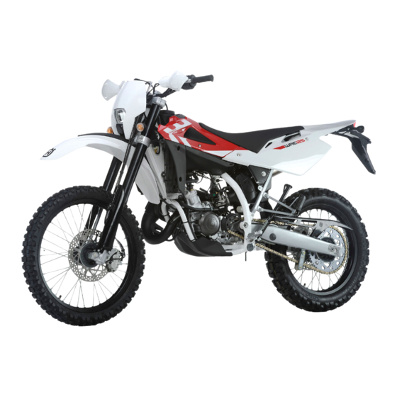
GENERAL INFORMATION WRE 125 H02633 Overall dimensions Wheelbase A (WRE) ................mm 1462 (57.56 in.) (SMS) ................mm 1462 (57.56 in.) Overall length B (WRE) ................mm 2208 (86.93 in.) (SMS) ................mm 2145 (84.49 in.) Overall width C ..............mm 825 (32.48 in.) Overall height D (WRE) ................ - Page 15 GENERAL INFORMATION SMS 125 H02634 Capacities Type Quantity Fuel tank capacity (reserve included) 98 octane unleaded fuel 9,5 l - 2.09 Imp. Gall 2.51 U.S. Gall Fuel reserve 2 l - 0.44 Imp. Gall 0.53 U.S. Gall Oil tank capacity 0.176 Imp.
-
Page 17: Maintenance
MAINTENANCE Section Ed. 05-2011... - Page 18 MAINTENANCE SCHEDULED MAINTENANCE CHART (TO BE CARRIED OUT AT THE HUSQVARNA DEALER) WRE - SMS 125 ENGINE PART EVERY AFTER THE FIRST EVERY EVERY EVERY EVERY REPLACE 500 km (310 mi) 1000 Km (621 mi) 5000 Km (3106 mi) 10000 Km (6213 mi) 15000 Km (9320 mi) 20000 Km (12427 mi)
- Page 19 MAINTENANCE SCHEDULED MAINTENANCE CHART (TO BE CARRIED OUT AT THE HUSQVARNA DEALER) WRE - SMS 125 CHASSIS PART EVERY AFTER THE FIRST EVERY EVERY EVERY EVERY REPLACE 3 HOURS 1000 Km (621 mi) 5000 Km (3106 mi) 10000 Km (6213 mi) 15000 Km (9320 mi) 20000 Km (12427 mi) AS REQUIRED...
-
Page 21: Troubleshooting
TROUBLESHOOTING Section Ed. 05-2011... - Page 22 TROUBLESHOOTING ENGINE Trouble Cause Remedy Engine does not start or has starting trou- Insufficient compression bles 1. Piston seized Replace 2. Connecting rod small or big end seized Replace 3. Worn piston ring Replace 4. Worn cylinder Replace 5. Cylinder head loosely tightened Tighten 6.
- Page 23 TROUBLESHOOTING Trouble Cause Remedy Engine is noisy Noise seems to come from piston 1. Too much piston-to-cylinder clearance Replace 2. Worn piston rings or piston grooves Replace 3. Too much carbon build-up in combustion chamber Clean or on piston crown Noise seems to come from crankshaft 1.
- Page 24 TROUBLESHOOTING Trouble Cause Remedy Gear shift pedal does not return to original 1. Weak or broken selector return spring Replace position 2. Worn shifter forks Replace Transmission jumps out of gear 1. Worn sliding gear dogs Replace 2. Worn gear grooves Replace 3.
- Page 25 TROUBLESHOOTING CHASSIS Trouble Cause Remedy The handlebar is hard to turn 1. Insufficient tyre pressure Inflate 2. Bearing adjuster ring nut or steering stem nut Adjust overtightened 3. Bent steering stem Replace bottom yoke 4. Worn or seized steering bearings Replace Handlebar vibration 1.
- Page 26 TROUBLESHOOTING ELECTRICAL SYSTEM (see also Section M) Trouble Cause Remedy The spark plug gets dirty easily 1. Dirty air filter Clean 2. Worn piston rings Replace 3. Worn piston or cylinder liner Replace 4. Mixture too rich Adjust carburettor Spark plug electrodes overheat 1.
-
Page 27: Settings And Adjustments
SETTINGS AND ADJUSTMENTS Section Ed. 05-2011... - Page 28 SETTINGS AND ADJUSTMENTS Saddle removal.....................D.4 Tank removal ....................D.4 Throttle cable adjustment ................D.6 Adjustment of the starter lever..............D.6 Idle adjustment .....................D.7 Clutch plate replacement ................D.8 Adjustment of the clutch control lever ............D.9 Front brake fluid level check ..............D.10 Rear brake pedal position adjustment ............D.11 Rear brake pedal free play adjustment............D.11 Rear brake fluid level check ...............D.12 Checking the oil level..................D.12...
- Page 29 SETTINGS AND ADJUSTMENTS WRE 125 H02628 SMS 125 H02630 SMS 125 H02629 SMS 125 H02631 Ed. 05-2011...
-
Page 30: Saddle Removal
SETTINGS AND ADJUSTMENTS Saddle removal Turn the rear fixing (1) counter clockwise, remove it and extract the saddle. Tank removal Remove the saddle as described in the relevant paragraph. Remove the screws (1) and the side panels. (8 mm Allen wrench) H02635 Remove the tank retaining screw (2). - Page 31 SETTINGS AND ADJUSTMENTS Lift the front part of the tank (6) and remove it from the bike with the scoops. H02638 Ed. 05-2011...
-
Page 32: Throttle Cable Adjustment
SETTINGS AND ADJUSTMENTS Throttle cable adjustment The throttle cable may be adjusted using the adjuster screw on the cable itself or the adjuster screw on the carburettor cover. To check for proper adjustment of throttle cable, proceed as follows: move the rubber cap (1) aside; move transmission sheath to and fro to ensure a play of approx. -
Page 33: Idle Adjustment
SETTINGS AND ADJUSTMENTS Idle adjustment Idling should be adjusted only when the engine is hot and throttle is closed, as follows: turn the idle speed adjuster screw (1) until setting 1500 RPM ± 100 (turn clock- wise to increase the speed and counter clockwise to reduce the speed). Exhaust gas contains poisonous carbon monoxide gas. -
Page 34: Clutch Plate Replacement
SETTINGS AND ADJUSTMENTS Clutch plate replacement Drain transmission oil as outlined in the relevant paragraph. Remove the brake pedal (1). Remove the five retaining screws (2) and the clutch cover (3). Using an 8 mm wrench, unscrew the five screws (4) securing the clutch springs. -
Page 35: Adjustment Of The Clutch Control Lever
SETTINGS AND ADJUSTMENTS Adjustment of the clutch control lever To adjust the clutch control lever, you will need to adjust cable tension using the adjuster on the lever. Remove the rubber protection (1). Loosen the lock ring nut (3) and turn the tensioner (2). There should be at least 10 mm (0.39 in.) free play (A) before the clutch begins to disengage. -
Page 36: Front Brake Fluid Level Check
SETTINGS AND ADJUSTMENTS Front brake fluid level check The level of the fluid in master cylinder reservoir must never be below the minimum value, which can be checked from the sight glass (1) on the side of master cylinder body. A decrease of the fluid level will let air into the system, hence an extension of the lever stroke. -
Page 37: Rear Brake Pedal Position Adjustment
SETTINGS AND ADJUSTMENTS Rear brake pedal position adjustment The position of the rear brake pedal with respect to the footrest may be adjusted according to individual needs. For adjusting, proceed as follows: Loosen the screw (1). Turn the cam (2) in order to raise or lower the brake pedal (3) within the range available (A). -
Page 38: Rear Brake Fluid Level Check
SETTINGS AND ADJUSTMENTS Rear brake fluid level check Master cylinder fluid level - visible through sight glass (1) - must be above the minimum notch on master cylinder reservoir. A decrease of the fluid level will let air into the system, hence an extension of the lever stroke. -
Page 39: Changing Transmission/Gearbox Oil
SETTINGS AND ADJUSTMENTS Changing transmission/gearbox oil Remove the engine guard (1) by undoing the screws (2). H02653 To completely replace the oil, unscrew the plug (3) under the oil sump and let oil come out, then screw the plug again with its gasket and pour fresh oil from the hole of the loading plug. -
Page 40: Engine Lubrication Oil Level
SETTINGS AND ADJUSTMENTS Engine lubrication oil level Remove the saddle, turning the rear pin (1) counterclockwise. Remove the cap (2). Visually check that the oil level in the tank is sufficient; if necessary, top up with the oil type indicated in the lubricant table. H02655 H06642 Exhaust valve cleaning / oil drainage... -
Page 41: Lubricating Oil Pump Drainage
SETTINGS AND ADJUSTMENTS Lubricating oil pump drainage Remove the saddle and side panel, as outlined in the relevant paragraph. Drainage is to be done with the engine off. Using the special pliers, loosen clamp onto pump (5) to carburettor pipe (4), and disconnect pipe. -
Page 42: Coolant Level Check
SETTINGS AND ADJUSTMENTS Coolant level check Check level (1) in right-hand radiator when engine is cold (place the motorcycle so that it is perpendicular to the ground). The coolant should be approximately 0.39 in. above the cells. The radiator cap features two locking positions: the first one is for prior discharge of pressure from the cooling system. -
Page 43: Coolant Replacement
SETTINGS AND ADJUSTMENTS Coolant replacement Place the vehicle on a flat ground and in horizontal position. Place a vessel of adequate capacity on the right side of the vehicle under the water pump (1). Loosen the exhaust screw (2) using an 8 mm wrench. Slowly open the RH radiator cap (3) and let the liquid drain. -
Page 44: Air Filter Check
SETTINGS AND ADJUSTMENTS Air filter check Remove the saddle as outlined in the relevant paragraph. Disconnect the battery cables (1) and (2) and remove the battery (3). H06646 Lift the engine oil reservoir (4). Undo the screw (5) and remove the filter (6). Detach the filter (6) from the subframe (7). -
Page 45: Assembly
SETTINGS AND ADJUSTMENTS Assembly To ensure tight fit, slightly (C) grease filter edge on side facing filter housing. While re-inserting the filter into its housing, make surs that piece (A) is turned up- wards and edge (B) is on the left lower side of the filter case. Reassemble the parts previously removed. -
Page 46: Chain Adjustment
SETTINGS AND ADJUSTMENTS Chain adjustment Chain should be checked, adjusted and lubricated as per the Maintenance Chart to ensure safety and prevent excessive wear. If the chain becomes badly worn or is poorly adjusted (i.e., if it is too loose or too taut), it could escape from sprocket or break. -
Page 47: Chain Lubrication
SETTINGS AND ADJUSTMENTS Chain lubrication Lubricate the chain following these instructions. Never use grease to lubricate the chain. Grease helps to accumulate dust and mud, which act as abrasive and help to rapidly wear out the chain, the front and rear sprockets. Disassembling and cleaning When particularly dirty, remove and clean the chain before lubrication. -
Page 48: Shock Absorber Adjustment
SETTINGS AND ADJUSTMENTS Shock absorber adjustment The rear shock absorber must be adjusted to suit rider weight and terrain condi- tions. Proceed as follows: 1. Place the motorcycle on the stand and measure distance (A). 2. Sit on the motorcycle in normal riding position with full riding gear on. 3. -
Page 49: Shock Absorber Spring Preload Adjustment
SETTINGS AND ADJUSTMENTS Shock absorber spring preload adjustment Proceed as follows: 1. Turn the rear fixing (1) counter clockwise and remove the saddle, unscrew the retaining screws (2) and remove the right-hand side panel (3). 2. Clean lock ring nut (4) and adjuster ring nut (5) of the spring (6). 3. -
Page 50: Front Fork Adjustment
SETTINGS AND ADJUSTMENTS Front fork adjustment Front fork has no adjustment. Steering bearing clearance adjustment For safety reasons, the steering should always be adjusted so that the handlebar turns freely and without play. To check steering adjustment, set a stand or a block under the engine and see that the front wheel is lifted from the ground. -
Page 51: Fuel Supply Hose Inspection
SETTINGS AND ADJUSTMENTS Fuel supply hose inspection Check the pipe (1) starting from tank cock and reaching the carburettor. If cracked, replace it by releasing the two clamps (2). H02683 H02658 Engine lubrication oil piping check Remove the saddle and right-hand side panel, as outlined in the relevant paragraph. -
Page 52: Exhaust System Check
SETTINGS AND ADJUSTMENTS Exhaust system check Remove exhaust system components as described in Section "E". Ensure that pipe (1) and silencer (2) do not show any sign of failure or damage: replace if cracked or damaged. Remove the right-hand side panel (3) and check the conditions of the silent-blocks (4). -
Page 53: Exhaust Valve Position Check
Exhaust valve position check H02846 H02848 The cylinder has a double exhaust valve system called H.T.S. (HUSQVARNA TORQUE SYSTEM), ensuring engine top performance. These valves are con- trolled by a centrifugal governor making them open at approx. 7500 rpm ± 200. -
Page 55: General Procedures
GENERAL PROCEDURES Section Ed. 05-2011... - Page 56 GENERAL PROCEDURES Foreword ......................E.3 Engine guard removal ..................E.4 Saddle removal.....................E.5 Side panel removal ..................E.5 Battery removal ....................E.5 Oil reservoir removal ..................E.6 Electronic control unit removal..............E.7 Rear chassis complete with mudguard and air box removal .......E.8 Exhaust system removal ................E.10 Fuel tank and scoop removal ..............E.12 Scoop removal....................E.14 Spoiler removal...................E.14...
-
Page 57: Foreword
GENERAL PROCEDURES Foreword This section describes the operations preliminary to engine removal. Please note that, in order to gain access to certain motorcycle components (rear shock absorber, electrical parts, wiring, etc.), it may be necessary to partially remove some parts. H02702 H02704 H02703... -
Page 58: Engine Guard Removal
GENERAL PROCEDURES Engine guard removal - Using an 8 mm wrench, loosen screws (1) Remove engine guard (2) releasing it from the rear support. H02705 H02707 H02706 Ed. 05-2011... -
Page 59: Saddle Removal
GENERAL PROCEDURES Saddle removal - Turn the rear fixing (1) counter clockwise and remove the saddle. H02655 Side panel removal Remove the saddle as described in the relevant paragraph. Using an 8 mm wrench, loosen retaining screws (1) and remove side panels (2) and (3). H02708 H02709 Battery removal Remove the saddle as outlined in the relevant paragraph. - Using an 8 mm Allen wrench, first remove the BLACK negative cable, then the RED positive cable (when reassembling, first connect the RED positive cable, then the BLACK negative cable); remove the battery (1) from its hous-... -
Page 60: Oil Reservoir Removal
GENERAL PROCEDURES Oil reservoir removal Remove saddle, side panels and tank as outlined in the relevant para- graphs. Disconnect the oil pump supply connector (1). Using an 8 mm wrench, loosen screw (2), and remove oil pump (3) with its mount. -
Page 61: Electronic Control Unit Removal
GENERAL PROCEDURES Electronic control unit removal Remove the saddle as outlined in the relevant paragraph. Remove control unit (1) from the special vibration mount (2). Release connector (3) from control unit (1) H02715 H02716 Ed. 05-2011... -
Page 62: Rear Chassis Complete With Mudguard And Air Box Removal
GENERAL PROCEDURES Rear chassis complete with mudguard and air box removal Remove saddle, side panels, tank, silencer, battery, oil reservoir and control unit (in this order), as outlined in the relevant paragraphs. Shear the plastic clips securing wiring to rear chassis. H02718 - Disconnect air temperature sensor connector (1) positioned inside filter box (widen tabs, and pull). - Page 63 GENERAL PROCEDURES To remove upper pin (7), loosen nut with a 12 mm wrench and pin with a 13 mm wrench. H02722 - Lift chassis (8) complete with filter box (9). H02717 Ed. 05-2011...
-
Page 64: Exhaust System Removal
GENERAL PROCEDURES Exhaust system removal H02723 Remove the saddle as described in the relevant paragraph. Remove the right-hand side panel as described in the relevant paragraph. Using an 8 mm T-wrench, remove silencer (2) retaining screws (1), and remove silencer from vehicle. H02724 E.10 Ed. - Page 65 GENERAL PROCEDURES Remove clamp (3) and disconnect secondary air circuit pipe (4) from exhaust manifold (5). H02725 Release the two springs (6). H02726 To remove manifold (5), loosen screw (7) with an 8 mm wrench. Check seal (8) and metal gasket (9) for wear. Change, if damaged. H02727 H02728 H02729...
-
Page 66: Fuel Tank And Scoop Removal
GENERAL PROCEDURES Fuel tank and scoop removal H02730 Remove the saddle as described in the relevant paragraph. Remove the side panels as described in the relevant paragraph. Remove the breather hose (1). H02731 E.12 Ed. 05-2011... - Page 67 GENERAL PROCEDURES Loosen tank retaining screw (2) (with an 8 mm Allen wrench). H02732 Close fuel cock (3), release clamp (5), and disconnect pipe (4). H02637 Raise the tank (6) from the front end, and remove it from bike complete with scoops (7).
-
Page 68: Scoop Removal
GENERAL PROCEDURES Scoop removal Remove the saddle and side panels, as outlined in the relevant para- graphs. Using an 8 mm wrench, loosen front screw (8) between scoop (7) and tank. H02734 Using an 8 mm wrench, loosen side screw (9) and upper screws (10) with a Phillips screwdriver; then remove scoop (7). -
Page 69: Voltage Regulator Removal
GENERAL PROCEDURES Voltage regulator removal Disconnect the connector (1). Loosen the two retaining screws (2) and remove the regulator (3). (8 mm wrench) H02738 Ignition coil removal Remove: saddle and fuel tank as described in the relevant paragraphs. Remove the spark plug cap (1). H02739 Remove the retaining screws (2) and then the coil (3). -
Page 70: Horn Removal
GENERAL PROCEDURES Horn removal Loosen the upper screw (1) securing the spoiler to the right-hand radiator. H02741 Disconnect the two connectors (2) and remove the horn (3) with its brack- H02742 Number plate holder removal Remove tail light as outlined in section M. Disconnect rear turning indicator connectors (1) and (2). -
Page 71: Air Box Removal
GENERAL PROCEDURES Air box removal Remove saddle, side panels, fuel tank, oil reservoir and silencer (in this order), as outlined in the relevant paragraphs. - Disconnect air temperature sensor connector (1) positioned inside filter box (widen tabs, and pull). H02718 - Loosen clamp (2) securing filter box to carburettor. H02745 Loosen the screws (3) using a 10 mm wrench. H02746 Loosen upper pin (4) using a 12 mm wrench on nut, and a 13 mm wrench on pin. - Page 72 GENERAL PROCEDURES - Overturn chassis (5) with filter box (6) without removing control unit and fuse and flasher holder bracket. H02751 - Using an 8 mm wrench, loosen the four screws (7), and remove filter box (6) from chassis. H02750 H02748 Using a 2.5 mm Allen wrench, loosen the two screws (8), and remove tem- perature sensor (9). H02752 E.18 Ed. 05-2011...
-
Page 73: Front Mudguard Removal
GENERAL PROCEDURES Using an 8 mm wrench, loosen the two screws (10), and remove shock absorber protection (11). H02753 Remove rivets (13), and remove upper rubber protection (12). - Remove the air filter. H02754 Front mudguard removal Using an 8 mm wrench, loosen the four screws (1), and remove mudguard (2). -
Page 74: Rear Brake Pedal Removal
GENERAL PROCEDURES Rear brake removal Using a 6 mm Allen wrench, loosen screw (1), and remove lever (2) complete with pump pushrod (3). H02756 Carburettor removal Close fuel cock (1), release clamp (3), and disconnect pipe (2). H02765 Disconnect TPS sensor connector (4). Important - Do not remove TPS from carburettor in order not to lose calibration. - Page 75 GENERAL PROCEDURES Loosen clamps (6), and disconnect mixture oil hose (5). H02749 H02764 Slightly turn carburettor (8) to the left, loosen screw (9), and remove starter control (10). H02762 H02761 Ed. 05-2011 E.21...
- Page 76 GENERAL PROCEDURES Loosen the two screws (11), and remove carburettor valve cover (12). H02760 H02759 Detach carburettor (8), and remove it. H02758 On reassembly, take care that carburettor breather hoses (13) are correctly positioned inside their seats and that they are not kinked.
-
Page 77: Secondary Drive Chain Removal
GENERAL PROCEDURES Secondary drive chain removal To remove chain, proceed as follows: Remove: screws (1), sprocket guard (2), clip (3), master link (4) and chain (5). H02673 H02767 Engine removal Remove the saddle as described in the relevant paragraph. Remove the fuel tank as described in the relevant paragraph. Remove the exhaust system as described in the relevant paragraph. - Page 78 GENERAL PROCEDURES Engine removal Lift retaining tab, and disconnect clutch cable (1). H02768 - Disconnect ignition connector (2), PICKUP connector (3), and coolant tem- perature sensor (4). H02769 H02770 Take off the spark plug cap (5). H02771 E.24 Ed. 05-2011...
- Page 79 GENERAL PROCEDURES Loosen clamp (6), and praise carburettor (7) off the intake duct. H02772 Open clamps (8), and disconnect pipes (9) from engine (10). H02773 Using a 27 mm wrench, loosen nut (11) on swinging arm shaft then, work- ing on the right side, remove swinging arm shaft until releasing engine, but without removing swinging arm.
-
Page 80: Radiator Removal
GENERAL PROCEDURES Radiator removal Remove the fuel tank together with scoops and spoilers as outlined in the relevant paragraphs. Drain all coolant as outlined in the relevant paragraph. Using an 8 mm wrench, loosen screws (2), and remove radiator protections (1). - Page 81 GENERAL PROCEDURES Open clamps (8), and disconnect hoses (9) from left-hand radiator (10). H06649 Open clamp (11), and disconnect the radiator connecting hose (12). H02780 Using an 8 mm wrench, loosen screws (13), and remove left-hand radiator (10). H02781 H02782 Ed.
-
Page 82: Thermostat Removal
GENERAL PROCEDURES Using an 8 mm wrench, loosen screws (14), and remove right-hand radiator (7). H02784 H02783 Thermostat removal Remove fuel tank, and drain all coolant as outlined in the relevant para- graph. Open the three clamps (1) securing the thermostat (2). Disconnect the hoses (3) and remove the thermostat (2). -
Page 83: Engine Disassembly
ENGINE DISASSEMBLY Section Ed. 05-2011... - Page 84 ENGINE DISASSEMBLY Right-hand side component and cover disassembly ........F.3 Clutch components ..................F.4 Clutch-side crankcase half component disassembly ........F.5 Sprocket-side component and cover disassembly ........F.9 Intake valve disassembly................F.12 Exhaust valve disassembly ................ F.13 Piston-cylinder-and-head assy disassembly ..........F.14 Splitting the crankcase ................
-
Page 85: Right-Hand Side Component And Cover Disassembly
ENGINE DISASSEMBLY Right-hand side component and cover disassembly 14 13 20 17 H06625 To make disassembly operations easier, it is recommended to place engine block onto a rotating support, securing it on the upper side. Loosen screw (1), and remove the kick start lever (2). (8 mm wrench) Loosen the two screws (3), and remove regulator cover (4). -
Page 86: Clutch Components
ENGINE DISASSEMBLY Clutch components H06622 Screw Washer Spring Pressure plate Clutch assembly Thrust washer Needle roller bearing Retainer Ball 10 Pushrod Clutch control shaft 12 Lock washer 13 Nut 14 Clutch hub 15 Washer 17 Clutch housing 18 Needle roller bearing 19 Spacer 20 Spacer 21 Washer... -
Page 87: Clutch-Side Crankcase Half Component Disassembly
ENGINE DISASSEMBLY Clutch-side crankcase half component disassembly Working crossways, loosen the five retaining screws (1) on clutch springs, and remove them together with the relevant washers (2) and springs (3). H06528 Remove pressure plate (4) and clutch plates pack (5) from hub. Slide thrust washer (6), axial roller bearing (7) and retainer (8) out of pri- mary shaft end. - Page 88 ENGINE DISASSEMBLY Carry out this operation using special tool part no. 8000 79015 with the ends inserted inside the two opposite grooves on clutch hub. Lock clutch hub in place with tool, and loosen locking nut (13) with a 22 mm socket wrench.
- Page 89 ENGINE DISASSEMBLY Countershaft nut (16) has a left-hand thread. Loosen countershaft nut (16) placing a 1/2 gear or an aluminium shim be- tween clutch housing gear (17) and countershaft gear (18). H06534 Slide clutch housing (17), the two needle roller cages (18) with spacer (19), the inner spacer (20) and three-tab washer (21) out of primary shaft.
- Page 90 ENGINE DISASSEMBLY Remove the Woodruff key from crankshaft. H06536 Slide countershaft idle gear (24) with the relevant shims (25) out of right crankcase half. H06537 Slide selector shaft (26) out of right crankcase half rear side. H06538 Ed. 05-2011...
-
Page 91: Sprocket-Side Component And Cover Disassembly
ENGINE DISASSEMBLY Disengage return spring (27) on starter shaft (28) from its retainer on right crankcase half. H06539 Working on the inner side, slide out starter shaft (28) assembly complete with control gear, and collect washer (29). H06540 Sprocket-side component and cover disassembly Loosen the three retaining screws (1), and remove cover (2). - Page 92 ENGINE DISASSEMBLY Using a chisel and a hammer, straighten the bent sections of lock washer (5) on sprocket sealing screw. H06542 Lock sprocket (6) in place using tool part no. 00YA2273 and then, with a 13 mm socket wrench, loosen sprocket sealing screw on output shaft. Slide out this screw, lock washer, large washer and sprocket.
- Page 93 ENGINE DISASSEMBLY Prevent rotor rotation using a suitable tool. Using a 17 mm socket wrench, loosen rotor sealing nut. Remove lock washer. H06544 Use tool (7) part no. 8000 51614, and secure it onto rotor with three screws having a suitable length. Holding the tool in place with a 19 mm Allen wrench and working clockwise on the central screw, remove rotor from crankshaft with a 17 mm Allen wrench.
-
Page 94: Intake Valve Disassembly
ENGINE DISASSEMBLY Loose the three retaining screws (8) on stator. Slide rubber block and plate (9) out of left crankcase half, and remove the complete stator (10). Remove the Woodruff key from crankshaft. H06546 Intake valve disassembly Using the special wrench part no. 8000 98431 loosen the four sealing screws (1) on intake valve unit (2). -
Page 95: Exhaust Valve Disassembly
ENGINE DISASSEMBLY Remove intake valve (2) from crankcase, and collect gasket (3). H06548 Exhaust valve disassembly - Remove exhaust valve control unit (1) ad described in the relevant paragraph. - Loosen screw (2), and remove parts (3), (4), (5) and (6). Remove screws (7) and cover (8). -
Page 96: Piston-Cylinder-And-Head Assy Disassembly
ENGINE DISASSEMBLY Piston-cylinder-and-head assy disassembly Head, cylinder and piston can be disassembled also at an earlier stage, as this procedure is independent of the disassembly operations carried out so far. The piston-cylinder-and-head assy removal proves now necessary in order to separate the crankcase halves. - Page 97 ENGINE DISASSEMBLY Slide cylinder (6) out of crankcase stud bolts, by duly supporting piston with your hands when it is separated from cylinder. WARNING - When removing the cylinder, do not let it rotate as piston ring end could enter gaps thus preventing piston removal and causing damage to the piston ring itself.
-
Page 98: Splitting The Crankcase
ENGINE DISASSEMBLY Splitting the crankcase Loosen the 12 retaining screws on left crankcase half. H06624 H06624 With the gearbox in neutral position, fit tool part no. 8000 79016 on left crank- case half (with 3 duly-sized "A" screws), work on the central pin and separate crankcase halves. -
Page 99: Crankshaft Removal
ENGINE DISASSEMBLY Using pliers, counteract spring action and turn ratchet to allow selector shaft removal. Slide out selector shaft from the left side. H06556 Crankshaft removal Should it be necessary to remove crankshaft from right crankcase half, use the same tool part no. 8000 79016 already used for crankcase splitting. Align tool holes with those on right crankcase half outer side, and secure tool with three screws of a suitable length. -
Page 101: Engine Overhaul
ENGINE OVERHAUL Section Ed. 05-2011... - Page 102 ENGINE OVERHAUL Cleaning parts ..................... G.3 Compression ratio check ................G.4 Cylinder ....................... G.5 Cylinder measuring..................G.5 Clearances ....................G.6 Piston......................G.6 Piston groove height ..................G.6 Cylinder to piston clearance ................ G.7 Piston pin ..................... G.7 Piston rings ....................G.8 Piston ring height ..................
-
Page 103: Cleaning Parts
ENGINE OVERHAUL Cleaning parts All parts must be cleaned with gasoline and dried with compressed air. During this procedure flammable vapours develop and metal particles may be blown at high speed, it is therefore recommended to perform this procedure away from open flames or sources of ignition, and to wear goggles. Ed. -
Page 104: Compression Ratio Check
ENGINE OVERHAUL Compression ratio check To check if the compression ratio is correct, proceed as follows: a) remove the cylinder together with the head from the crankcase ; b) remove the piston from the connecting rod, carefully clean it and install it in- side cylinder until it rests against the corresponding sector on the combustion chamber (such part, as well, has to be cleaned from deposits) c) screw a dial gauge into the spark plug hole, and reset it on the piston position... -
Page 105: Cylinder
ENGINE OVERHAUL Cylinder Light alloy cylinder with "NIKASIL"-coated liner. Once the cylinder has been activated, the max. allowed out-of-round value is 0.015 mm (0.0006 in.). In case of damages or excessive wear the cylinder shall be replaced. Cylinders are marked by a letter or a colour referring to the class they belong to. Cylinder measuring Check that the internal surface is perfectly smooth and free from scuffing. -
Page 106: Clearances
ENGINE OVERHAUL Clearances To ensure the best operating conditions and maximum performance, all clearances must be within the specified tolerance. A tight fit will lead to seizure as moving parts heat up; whereas a loose fit will cause annoying vibration resulting in early wear of moving parts. -
Page 107: Cylinder To Piston Clearance
ENGINE OVERHAUL Cylinder to piston clearance The piston-cylinder units are supplied already coupled; should the cylinders and pistons of some units have been accidentally mixed up, it will be necessary to measure the diameters as outlined in the previous paragraphs. Take these measurements at a stabilised temperature of 20°C. -
Page 108: Piston Rings
ENGINE OVERHAUL Piston rings Visually check the piston ring and the relevant seat in the piston. If the piston ring is worn or damaged, it has to be replaced (the set is available as spare part). If the piston ring seat is worn or damaged as well, both piston and piston ring shall be replaced. -
Page 109: Piston Pin-Piston-Connecting Rod Small End Clearance
ENGINE OVERHAUL Piston pin-piston-connecting rod small end clearance The table below is a list of the possible clearances allowing to reach the right radial clearance of 0.002÷0.010 mm (0.000078÷0.000393 in.). If, during engine overhaul, a radial clearance higher than the max. allowed value of 0.015 (0.00059 in.) is found and the colour mark (C) is no longer vis- ible on the connecting rod, it will be necessary to measure the diameter "A"... -
Page 110: Pin-Flywheel-Connecting Rod Big End Clearance
ENGINE OVERHAUL Pin-flywheel-connecting rod big end clearance The table below is a list of the possible clearances allowing to reach the right radial clearance of 0.20÷0.028 mm. If, during engine overhaul, a radial clear- ance higher than the max. allowed value of 0.050 is found, it will not be neces- sary to measure the diameter "E"... -
Page 111: Connecting Rod
ENGINE OVERHAUL Connecting rod Due to the stresses the connecting rod is subject to, its original dimensions change in a more or less noticeable way. The connecting rod tests are meant to check its wholeness. Should readings not comply with the max. allowed wear limits, it will be neces- sary to replace it. -
Page 112: Head
ENGINE OVERHAUL Head Remove carbon deposits from the combustion chamber. Make sure that there is no cracking and that the sealing surfaces do not feature scoring, dents or any other kind of damages. Flatness must be perfect as well as spark plug seat threading. -
Page 113: Various Crankshaft Straightness Check
ENGINE OVERHAUL Various crankshaft straightness check Place the crankshaft between centres and take the measurement with a dial gauge, checking that the detected value does not exceed 0.05 mm (0.00196 in.). H06578 Bearings Carefully wash bearings with mixture and dry with compressed air without turn- ing them. -
Page 114: Needle Roller Bearing Replacement
ENGINE OVERHAUL Needle roller bearing replacement To remove the needle roller bearing of the water pump shaft, use special tool part no. 8000 43824. H06581 Oil seal replacement Replace the oil seals at each engine overhaul. To install the new oil seals, in- sert them squarely into their housings and use suitable driver tools. -
Page 115: Clutch Unit
ENGINE OVERHAUL Clutch unit Inspect all clutch components to make sure they are in the best conditions. Clutch plates should show no signs of bluing, scoring or distortion; the plates fitted with friction material shall have a thickness complying with the values indicated in the table. -
Page 116: Friction Plate To Clutch Housing Clearance
ENGINE OVERHAUL Friction plate to clutch housing clearance Standard Max. size limit 0.25÷0.35 mm 0.8 mm (0.0098÷0.0138 in.) (0.031 in.) H06585 Clutch plate distortion Standard Max. wear limit 0.2 mm (within 0.05 mm) Friction plate (0.0078 in.) (0.0019 in.) 0.25 mm (within 0.01 mm) Steel plate (0.0098 in.) -
Page 117: Gear Change
ENGINE OVERHAUL Gear change Check that the gear front coupling teeth are in perfect conditions, make sure that the idle gears rotate freely on their shafts and that their clearance is not higher than 0.10 mm (0.004 in.). The shaft threading and grooves must be in perfect conditions. Moreover, make sure that the gear selector components are in good conditions. -
Page 118: Shifter Forks
ENGINE OVERHAUL Shifter forks Visually inspect the shifter forks and replace any bent fork. A bent fork will make gears hard to engage and let the transmission jump out of gear unex- pectedly under loading. Fork slider thickness Standard Max. size limit 3.35÷3.43 mm 3.31 mm (0.132÷0.135 in.) -
Page 119: Control Shaft Groove Width
ENGINE OVERHAUL Control shaft groove width Standard Max. size limit 6.05÷6.15 mm 6.20 mm (0.238÷0.242 in.) (0.244 in.) H06592 Ed. 05-2011 G.19... -
Page 120: Carburettor
ENGINE OVERHAUL Carburettor H06593 NOTE adjuster screws are on the left side of the motorcycle. Description Ref. Dell'Orto PHBH 28 1 Throttle valve D 48/2 groove (*) 2 Taper needle U 38 3 Idle diffuser N° 2 6.5 gr 4 Floater 5 Jet at maximum HN 268 6 Main nozzle... -
Page 121: Carburettor Overhaul
ENGINE OVERHAUL Carburettor overhaul Clean all carburettor components thoroughly with gasoline and dry them with compressed air. Clean all jets and holes thoroughly blowing them with com- pressed air. Never use tool bits or metal wire. Check that the slide valve is in good condition. -
Page 122: Main Jet Correction Factor
ENGINE OVERHAUL Main jet correction factor The main jet strongly affects carburetion, hence the general performance of the engine. Climate factors such as external tem- perature and altitude greatly affect the behaviour of the air-fuel mixture within the carburettor. It is thus necessary to modify the original jet size, inferring the correction factor on the graph below. -
Page 123: Washer Valve
ENGINE OVERHAUL Washer valve Make sure that plates are neither worn nor broken. Should this be the case, replace the plates and the plate stops. When refitting the removed parts, apply Loctite on the screws. H06597 Exhaust valve Clean the valves with a spark plug cleaner brush or with thin sand paper. Clean and replace them following the intervals indicated in section "B". -
Page 125: Engine Assembly
ENGINE ASSEMBLY Section Ed. 05-2011... - Page 126 ENGINE ASSEMBLY General instructions..................H.3 Items summary and general assembly notes ..........H.4 Crankshaft reassembly .................H.4 Gear shift part reassembly ................H.5 Piston-cylinder-and-head reassembly ............H.9 Primary drive and countershaft gears line up ..........H.12 Clutch reassembly ..................H.13 Right cover reassembly ................H.15 Exhaust valve reassembly ................H.17 Ed.
- Page 127 ENGINE ASSEMBLY General To reassemble, reverse the disassembly procedure. Any special instructions concerning reassembly operations are expressly high- lighted in the text. Gaskets, oil seals, metal clips, sealing washers in deformable material (copper, aluminium, fibre etc.) and self- locking nuts must always be replaced. Bearing specifications and dimensions have been calculated for a certain operating life.
-
Page 128: Items Summary And General Assembly Notes
ENGINE ASSEMBLY Item summary and general assembly notes PARTS PROCEDURES Flywheel - Crankshaft taper end Degrease with suitable degreasers Crankcase crankshaft Fit the shaft inside the pre-heated bearings Starter drive shaft Press with "Loctite 648" Crankshaft - Bearings Pre-heating seat at 100°C/125°C Piston pin - Connecting rod - Cage Check selection colours coupling (see Sect. -
Page 129: Gear Shift Part Reassembly
ENGINE ASSEMBLY Gear shift part reassembly Fit the original shim at the end of the output shaft. If the selector shaft or the gear shafts are replaced, it will be necessary to determine the thickness of the shims to be fitted in order to achieve the correct axial clearance. Selector shaft and gear shafts axial clearance: 0.3÷0.4 mm (0.012÷.015 in.). - Page 130 ENGINE ASSEMBLY Fit the selector shaft with its bearing and sector gear well lubricated with engine oil in the right half crankcase. If the ratchet is already assembled on the outer side of the crankcase half, use pliers to counteract the action of the spring so as to allow the insertion of the selector shaft.
- Page 131 ENGINE ASSEMBLY WARNING - In case of incorrect sealing, the following operating failures may occur: Air seepage causing a leaner mixture and possible engine seizure. Oil leak from gearbox area to crankshaft area; this may lead to a fast consumption of lubricant causing gearbox overheating and seizure.
- Page 132 ENGINE ASSEMBLY Fit the original shim (4) on starter shaft end, and insert it in the right crankcase half seat. Mind the positioning of the clutch spring end, it must be fitted between the rear end of the crankcase half and the protruding tooth (D). Pre-charge the lever return spring by turning its end clockwise until it is fitted inside the special crankcase half hole.
-
Page 133: Piston-Cylinder-And-Head Reassembly
ENGINE ASSEMBLY Fit the countershaft drive gear (5) with the original shims (6). H06608 Fit the spacer (9) and the tab in the crankshaft seat, and install the primary drive gear (7) and the water pump control gear (8). H06609 To correctly line up the primary drive and countershaft gears, the position of the crankshaft gear must correspond to that of the piston at TDC. - Page 134 ENGINE ASSEMBLY Lubricate all the parts to be assembled with engine oil and fit the cylinder into the piston by compressing the ends of the piston rings with your fingers (or us- ing a universal piston installation tool). During installation, avoid rotating the cylinder since piston ring ends could enter ducts.
- Page 135 ENGINE ASSEMBLY Rotate the crankshaft and check that the piston (1) slides freely inside cylin- der. Tighten the nuts (2) between cylinder and crankcase to the recommended torque, working crossways. Fit the duly greased external (3) and internal (4) O-rings in the cylinder seats and insert the head inside cylinder stud bolts.
-
Page 136: Primary Drive And Countershaft Gears Line Up
ENGINE ASSEMBLY Primary drive and countershaft gears line up Fit a dial gauge on the head to determine the condition of the piston at the top dead centre. Insert on the primary shaft the three-tab washer (1), the inner spacer and the two roller cages (2) with spacer (3). -
Page 137: Clutch Reassembly
ENGINE ASSEMBLY Clutch reassembly Fit bushing, spring and clutch control lever shaft inside L.H. crankcase half seat. Fit the washer (1) and the disengagement group into the primary shaft in the following order: the fist rod and the ball. All these parts must be greased before reassembly. - Page 138 ENGINE ASSEMBLY Install the lock washer and hub locking nut. While locking the hub with tool part no. 8000 79015, lock the nut with a 22 mm socket wrench to the specified tightening torque. Rivet washer onto nut. H06617 Fit the friction plates starting by one of the seven line steel plates (3) and alternate it with one of the six friction plates (4);...
-
Page 139: Right Cover Reassembly
ENGINE ASSEMBLY Fit the bearing thrust washer (7) and assemble the pressure plate (8). H06618 Fit the clutch springs (9) and lock them onto hub with the suitable washers and screws. H06619 Right cover reassembly Install the original shim at the ends of water pump control shaft (A) and intro- duce it inside its seat on RH crankcase half. - Page 140 ENGINE ASSEMBLY Install the gasket on the crankcase half, and check the correct position of the centring bushings; proceed to RH cover reassembly, taking care that the water pump control shaft end can be easily installed inside its special cover seat. H06638 Insert the eight retaining screws, taking care that the one at the rear centring bushing (white arrow) is longer than the other ones.
-
Page 141: Exhaust Valve Reassembly
ENGINE ASSEMBLY Exhaust valve reassembly To reassemble the exhaust valves, simply reverse the removal procedure minding that with completely closed valves, the min. distance from the piston must be equal to or grater than 0.4÷0.5 mm (0.0157÷0.0197 in.). On bushings (A), check the wear of the seats holes for pin (B); if worn, replace the parts. -
Page 143: Front Suspension
FRONT SUSPENSION Section Ed. 05-2011... - Page 144 FRONT SUSPENSION Front fork removal ..................I.4 Front fork overhaul ..................I.6 Key ....................... I.6 Disassembly ....................I.7 Assembly ...................... I.9 Oil replacement ..................I.10 Ed. 05-2011...
- Page 145 FRONT SUSPENSION WRE 125 H02628 SMS 125 H02630 SMS 125 H02629 SMS 125 H02631 Ed. 05-2011...
-
Page 146: Front Fork Removal
FRONT SUSPENSION Front fork removal Measure height "A" (it will need to be restored to original value on assembly). Set a block under the engine and see that the front wheel is lifted from the ground and then proceed as follows: H02787 H02786 remove the screws (1) and the brake line clamp on the left-hand side;... - Page 147 FRONT SUSPENSION remove the brake calliper from the L.H. fork leg loosening the two retaining screws (3); remove the front wheel as described in Section "Y"; H02789 loosen the bolts (4) that secure the fork legs to steering head and bottom yoke;...
-
Page 148: Front Fork Overhaul
FRONT SUSPENSION Front fork overhaul H06650 1) Bottom yoke with pin 2) Steering head 3) Nut 4) Tube spacer 5) Cap 6) Outer tube 7) LH damper unit 8) RH damper unit 9) Ring nut 10) Clamp 11) Leg protection Ed. -
Page 149: Disassembly
FRONT SUSPENSION Disassembly Using a 30 mm Allen wrench, loosen upper cap (1) Completely loosen cap and remove it. Push slider (2) downwards onto inner tube. H02792 Screw a threaded bar (A) onto inner shock absorber rod. Pull absorber rod upwards using the bar and, at the same time, push upper retainer (3) downwards with your hand so as to slide out the two split rings (4). - Page 150 FRONT SUSPENSION Remove dust seal (5) prising it off with a screwdriver (take care not to dam- age inner seal lip). H02795 Using a thin screwdriver, remove slider inner retaining ring (6). When removing the sealing ring (7), it is advisable to protect its lip with a special bush (B).
-
Page 151: Assembly
FRONT SUSPENSION Assembly Install lower retainer (8), with the discharged side pointing outwards. H02799 Slide sealing ring (7) inside the special bumper (C), and drive it fully home inside slider. Lock it inside slider with the retaining ring (6). H02800 Install it on the duly-lubricated dust seal tube (5), and move it downwards along tube. -
Page 152: Oil Replacement
FRONT SUSPENSION Lubricate inner tube and insert it inside slider (2). This operation is made easier thanks to pipe tapered end. Install the previously-assembled dust seal onto slider, and drive this latter fully home onto tube. H02802 Oil replacement Pour 520 cc of recommended oil inside inner tube, pumping rod to full travel several times to allow oil distribution inside shock absorber. - Page 153 FRONT SUSPENSION Pull rod outwards and, at the same time, push retainer (3) downwards so as to allow split rings (4) correct insertion. Leave bar and retainer, and check that split rings are correctly installed onto rod. H02805 Grease the O-ring (9) positioned onto cap (1) Screw cap (1) onto slider (2).
-
Page 155: Rear Suspension
REAR SUSPENSION Section Ed. 05-2011... - Page 156 REAR SUSPENSION Rear shock absorber ..................J.3 Lubrication points (grease) ................J.3 Rear suspension....................J.4 Type of suspension..................J.4 Rear shock absorber removal ...............J.5 Disassembling and servicing the swinging arm ..........J.6 Servicing the swinging arm shaft ..............J.7 Servicing the rear suspension drop drag link ..........J.7 Chain roller, chain guide, chain slider ............J.8 Ed.
-
Page 157: Rear Shock Absorber
REAR SUSPENSION Rear shock absorber TIGHTENING TORQUE FIGURES 44 ÷49 Nm/ 4.4 ÷4.5 Kgm/ 32.5-36.2 H/Lb H02807 H02808 Lubrication points (grease) H02809 H02810 Ed. 05-2011... -
Page 158: Type Of Suspension
REAR SUSPENSION Rear suspension The rising-rate rear suspension is made up of a shock absorber, a linkage system and a swinging arm. The spring preload of the shock absorber can be adjusted to suit riding and terrain conditions. Periodically check all components for wear. Type of suspension Steel swinging arm suspension with hydraulic single shock absorber. -
Page 159: Rear Shock Absorber Removal
REAR SUSPENSION Rear shock absorber removal Fit a support under the engine so that the rear wheel is raised off the ground. Remove rear chassis, as described in paragraph E - General Procedures. Using a 14 mm wrench, loosen nut (1) on bike left side. H02812 Slightly raise rear swinging arm, and remove lower pin (2) from the right side. -
Page 160: Disassembling And Servicing The Swinging Arm
REAR SUSPENSION Disassembling and servicing the swinging arm Set a stand or a block under the engine and see that the rear wheel is lifted from the ground. Remove secondary drive chain (1), release rear brake line (3) from swinging arm (2), and remove chain guard (4) as outlined in the relevant paragraphs (see section E). -
Page 161: Servicing The Swinging Arm Shaft
REAR SUSPENSION Servicing the swinging arm shaft Check shaft taper using a dial gauge. Place the shaft on two identical reference blocks. Turn the shaft and move the dial gauge horizontally to determine the amount of distortion. Service limit: 0.30 mm. H00428 Servicing the rear suspension drop and drag link With drop link (1) and drag link (2) still in place (connected to swinging arm and... -
Page 162: Chain Roller, Chain Guide, Chain Slider
REAR SUSPENSION Chain roller, chain guide, chain slider Check the wear of the above-mentioned elements and replace them when necessary. Check the chain guide alignment, and remember that a bent element can cause chain early wear. In this case, chain might unwrap from the sprocket. -
Page 163: Brakes
BRAKES Section Ed. 05-2011... - Page 164 BRAKES Braking system ..................... L.3 Brake disc ..................... L.4 Checking brake pads for wear / replacing the pads ........L.5 Bleeding the front braking system ..............L.6 Bleeding the rear braking system ..............L.7 Changing the fluid..................L.8 Removal of the rear braking system ............L.11 Removal of the front braking system ............
-
Page 165: Braking System
BRAKES Braking system The braking system uses two independent circuits. Each system is equipped with a brake calliper connected to a master cylinder with a fluid reservoir. 1. Front brake lever 2. Front brake master cylinder with fluid reservoir 3. Front brake line 4. -
Page 166: Brake Disc
BRAKES Brake disc Checking the brake disc is an important safety procedure; the disc must be spot- less, i.e. free from corrosion, oil or other dirt or deep scoring. Front brake disc diameter: 260 mm Front brake disc thickness (when new): 3.0 mm Wear limit: 2.5 mm Rear brake disc diameter: 240 mm Rear brake disc thickness (when new): 4.0 mm... -
Page 167: Checking Brake Pads For Wear / Replacing The Pads
BRAKES Checking brake pads for wear / replacing the pads Check brake pad wear. Service limit ”A” 3.8 mm (front and rear pads) If service limit is exceeded, always replace the pads in pairs. Be careful that no brake fluid or any oil gets on brake pads or discs. Clean off with alcohol any fluid or oil that inadvertently gets on the pads or disc. -
Page 168: Bleeding The Front Braking System
BRAKES Bleeding the front braking system A long travel and mushy feel of the brake lever indicate that there is air in the system and the brake needs bleeding. Bleeding procedure is as follows: Take the rubber cap off the bleed valve (1). Attach a clear plastic hose to the calliper bleed valve and place the other end of the hose in a vessel (make sure the hose end stays dipped in the fluid throughout the procedure). -
Page 169: Bleeding The Rear Braking System
BRAKES Bleeding the rear braking system A long travel and mushy feel of the brake pedal indicate that there is air in the system and the brake needs bleeding. Bleeding procedure is as follows: Remove reservoir cap (A) (21 mm wrench) and diaphragm and fill with fluid (DOT 4). -
Page 170: Changing The Fluid
BRAKES Changing the fluid Brake fluid should be checked and changed as per the "Maintenance Chart" (see Section B), or earlier if contaminated with debris or water. Do not change brake fluid in the rain or with a strong wind. Use only fluid taken from a sealed container (DOT 4). - Page 171 BRAKES Remove the reservoir cap (2) or (2A) 21 mm wrench and the rubber gaiter. Loosen the bleed valve on the calliper. Pump the brake lever (3) or the brake pedal (3A) until draining all fluid. Tighten the bleed valve and fill the reservoir with fresh fluid. Loosen the bleed valve, operate lever or pedal, tighten the valve keeping lever or pedal pressed and then release quickly.
- Page 172 BRAKES Periodically check the connecting hoses (C) and (D) (see Scheduled Maintenance Chart, Section B): replace worn or cracked hoses. H02836 H02837 L.10 Ed. 05-2011...
-
Page 173: Removal Of The Rear Braking System
BRAKES Removal of the rear braking system Remove the rear wheel as outlined in the paragraph (see chapter Y). Remove the hose (2) supports (1) by loosening the screws (3) using an 8 mm wrench. H02838 Loosen the two screws (4) and remove the pump (5) by disconnecting the STOP micro switch connector (6). -
Page 174: Removal Of The Front Braking System
BRAKES Removal of the front braking system Remove the front wheel (1) as outlined in the relevant paragraph (see sec- tion Y). Loosen the screws (3) and remove the block (2). H02842 Loosen the two screws (5) and disconnect the brake calliper (6). H02841 Release the hose (7) from the support (8). -
Page 175: Electrical System
ELECTRICAL SYSTEM Section Ed. 05-2011... - Page 176 ELECTRICAL SYSTEM Wiring diagram ................... M.5 Key to wiring diagram ................. M.5 Colour coding key ..................M.5 Electrical components location ..............M.6 Electrical components location ..............M.8 Checking generator stator windings resistance .......... M.9 Generator performance ................M.9 Alternator inspection ................. M.10 Electronic ignition system .................
- Page 177 ELECTRICAL SYSTEM TROUBLESHOOTING ................M.35 CHARGING SYSTEM ................M.35 ELECTRONIC IGNITION SYSTEM ............M.35 Connector positioning ................M.36 Bike left-hand side ..................M.36 Bike right-hand side .................. M.37 Front side, under headlamp fairing ............M.38 Under the saddle ..................M.38 Rear side, under tail light .................
- Page 178 ELECTRICAL SYSTEM Ed. 05-2011...
-
Page 179: Key To Wiring Diagram
ELECTRICAL SYSTEM Wiring diagram 22 23 H02524 Key to wiring diagram 24. Water temperature sensor Gr/B ....Grey/Blue 25. Alternator Gr/Bk .... Grey/Black 1. Battery 26. Voltage regulator O ....Orange 2. Electronic control unit 27. Rear L.H. turning indicator O/B .... -
Page 180: Electrical Components Location
ELECTRICAL SYSTEM Electrical component location The ignition system includes the following elements: Generator (1), on the inner side of L.H. crankcase half cover; H02525 Electronic ignition coil (2) under the fuel tank; H02526 Electronic control unit (3) under the saddle; H06651 Voltage regulator (4) on steering tube left side;... - Page 181 ELECTRICAL SYSTEM Spark plug (5) on cylinder head; Spark plug cap (5a); H02529 TPS sensor (6) on carburettor; H02530 H06652 Oil pump (7) positioned on right-hand rear chassis; Air temperature sensor (8) positioned inside filter box, close to oil pump; Coolant temperature sensor (9);...
- Page 182 ELECTRICAL SYSTEM Electrical component location The electrical system includes the following elements: - 12V-4Ah Battery (11) under the saddle; H06653 Turning indicator flasher (12) on left side of rear chassis; Fuses (13) on utilities holder plate, on left side of rear chassis; H02535 Headlamp (14) with 12V-35/35W twin halogen bulb and 12V-3W parking light bulb;...
-
Page 183: Checking Generator Stator Windings Resistance
ELECTRICAL SYSTEM Checking generator stator windings resistance The generator consists of a 12 V alternator with a power of 160 at 6,000 rpm, positioned inside engine left side cover. Ignition current start (spark): approx. 350 rpm. H02539 Measure across the terminals of the connector (1); correct value is about 0.6 . If resistance is outside the specified limits, replace the complete generator. -
Page 184: Alternator Inspection
ELECTRICAL SYSTEM Alternator inspection Disconnect the three yellow cables coming from the alternator from the regulator, taking care to properly insulate them so as not to let them contact each other. Take engine to approx. 3,000 rpm, and measure the open-circuit voltage using an alternate current voltmeter with a scale up to at least 50V. -
Page 185: Charging System
ELECTRICAL SYSTEM CHARGING SYSTEM The charging system is composed of: - Alternator (1); - Voltage regulator/rectifier (2); - 20A fuse (3); - Battery (4). The alternated current generated by the alternator is converted into direct cur- rent by the voltage regulator/rectifier. The voltage regulator/rectifier serves a dual purpose: it provides overvoltage protection for the battery and converts alternated current into direct current. -
Page 186: Charging System Inspections
ELECTRICAL SYSTEM CHARGING SYSTEM INSPECTIONS Current loss at the battery Remove the saddle (as outlined in the relevant paragraph) to gain access to the battery (1). Disconnect the BLACK negative cable from the battery. Measure current across the negative terminal of the battery and the negative cable using a meter. -
Page 187: Checking Coil Windings Resistance
ELECTRICAL SYSTEM Checking coil windings resistance Remove saddle and fuel tank (see relevant paragraph) to gain access to the coil (1). Disconnect the coil connector from the wiring, remove retaining screws and coil, and measure resistance in the primary and secondary windings with a meter. Induction coil: Primary winding resistance: 4.5 ±15% at 20°C. -
Page 188: Electronic Control Unit (Ecu)
ELECTRICAL SYSTEM Electronic control unit (ECU) Remove the saddle as described in Section E to gain access to the electronic control unit (1). Capacitive injection, i.e the spark on spark plug is obtained thanks to the discharge of a condenser - positioned inside control unit - through a capacitive coil. Spark ignites based on an advance table relating to the RPM values and throt- tle position. -
Page 189: Battery
ELECTRICAL SYSTEM BATTERY The battery (1) is a sealed-for-life, maintenance-free battery. If the vehicle remains unused for long periods, it is recommended to disconnect the battery from the electrical system and store it in a dry place. After an intensive use of the battery, it is advisable to carry out a standard slow charging cycle (12V-4Ah battery: 0.6A for 8 hours). -
Page 190: Carburettor Throttle Position Sensor (Tps) Inspection
ELECTRICAL SYSTEM Carburettor throttle position sensor (TPS) inspection Disconnect pipe from TPS on carburettor and, with the tester in OHM mode, position terminals across poles B and C on sensor, turn throttle twistgrip from the fully closed to the fully open position. Check that the resistance value cor- responds to the one specified in the table. -
Page 191: Checking Air Temperature Sensor
ELECTRICAL SYSTEM The following operations must be carried out with the engine off. Turn the ignition key (3) to "ON", oil warning light (4) will flash to indicate that the self-learning mode is active. With the throttle control released, press Engine Stop key (6), and keep it pressed: oil warning light (4) will start flashing more quickly. -
Page 192: Checking Coolant Temperature Sensor
ELECTRICAL SYSTEM Checking coolant temperature sensor Remove cap (1), disconnect electric contacts, and remove thermostat from head. Connect coolant temperature sensor (2) to an ohmmeter, and dip it inside the oil contained inside a pan. Heat up oil to slowly increase its temperature, and observe the values shown by the thermometer and ohmmeter. -
Page 193: Headlight Unit With Front Fairing Removal
ELECTRICAL SYSTEM Headlight unit with front fairing removal Using an 8 mm wrench, loosen screw (1). H02558 Move headlamp fairing (2) forward, and lift it to release damping pads (3) from their mounts (4). H02559 Open pipe support (5), and slide out front brake pipe (6) and speed sensor cable (7). -
Page 194: Removing Headlight From Front Fairing
ELECTRICAL SYSTEM Removing headlight from front fairing Remove the headlight unit complete with front fairing as outlined in the relevant paragraph. Loosen beam adjuster screw (1). H02565 Disconnect headlight connector (2). Widen the supporting tabs (3), and remove headlight (4) from the inside. H02564 M.20 Ed. -
Page 195: Front Turning Indicator Removal
ELECTRICAL SYSTEM Front turning indicator removal Remove the headlight unit complete with front fairing as outlined in the relevant paragraph. Disconnect connectors (1) and (2) of right and left turn indicators, respec- tively. H02566 Using a 10 mm wrench on the inside and an 8 mm wrench on the outside, loosen screws (3) and remove turning indicators (4). -
Page 196: Headlamp, Tail Light
ELECTRICAL SYSTEM HEADLAMP, TAIL LIGHT Headlamp adjustment The headlamp features a twin bulb for low and high beam and a festoon bulb for the city or parking light. Beam setting needs to be performed accurately; proceed as follows: - Place the motorcycle 10 metres away from a vertical wall; - the motorcycle must be on level ground and the optical axis of the headlamp must be perpendicular to the wall;... -
Page 197: Tail Light Replacement
ELECTRICAL SYSTEM release the bulb holder clips (3) and take out bulb (4); H02570 Headlamp bulb (4) is of the halogen type (H4); be careful when replacing it since the glass part shall not be touched with bare hands. To replace the parking light bulb (5) extract it from the inside cover. Once the bulb has been replaced, reverse the above procedure to reassem- ble. -
Page 198: Number Plate Bulb Replacement
ELECTRICAL SYSTEM Number plate bulb replacement - Loosen screw (1) and remove the number plate bulb (2) from the mud- guard. H02574 - Extract the bulb holder (3) with the bulb (4) from the housing. - Pull the bulb (4) to detach it from bulb holder. Once the bulb has been replaced, reverse the above procedure to reassem- ble. -
Page 199: Rear Turning Indicator Removal
ELECTRICAL SYSTEM Rear turning indicator removal Remove the tail light as outlined in the relevant paragraph. Disconnect connectors (1) and (2) of right and left turn indicators, respec- tively. H02575 Slide turning indicator cables out of rubber gaiter (3). H02576 Using a 10 mm wrench on the inside and an 8 mm wrench on the outside, loosen screws (4) and remove turning indicators (5). -
Page 200: Rear Wiring Harness Replacement
ELECTRICAL SYSTEM Rear wiring harness replacement Remove the left body panel as outlined in section E. Remove the tail light as outlined in the relevant paragraph. Disconnect connector (1) and cut clamps securing wiring harness to chas- sis. Disconnect rear turning indicator connectors, and remove wiring harness. TWO TYPES OF EqUIVALENT, FULLY INTERCHANGEABLE WIR- ING HARNESSES, BUT WITH A DIFFERENT SHAPE, ARE AVAIL- ABLE. -
Page 201: Type "B" Wiring Harness
ELECTRICAL SYSTEM Type "B" wiring harness H06635 1= Main wiring harness connector 2= Main wiring harness connector 3= LH turning indicator signal (RED/BLACK) 4= RH turning indicator signal (YELLOW) 5= Number plate light signal (SKY BLUE) 6= Ground cables H06636 Ed. -
Page 202: Handlebar Switches
ELECTRICAL SYSTEM Handlebar switches Measure continuity on the different switches using a meter. Replace any part found to be faulty. Right-hand switch 1 Engine stop button COLOUR POSITION H02611 Left-hand switch High beam flasher (self-cancelling) High beam switch Low beam switch Left-hand turning indicators (self-cancelling) Right-hand turning indicators (self-cancelling) To deactivate the turning indicators, press the control lever after it is returned... - Page 203 ELECTRICAL SYSTEM G-Bk Colour coding key B ....Blue Bk ....Black B-Bk ....Blue-Black B-W ....Blue-White G ....Green G-Bk ..... Green-Black G-W ....Green-White Gr ....Grey Y ....Yellow R ....Red B-Bk Sb ....Sky blue W ....
- Page 204 ELECTRICAL SYSTEM FUSES • When you find a blown fuse (1), always investigate and eliminate the cause before replacing it. • Never replace a fuse with another fuse with a different rating. • Never use a wire or other makeshift repair techniques instead of installing a new fuse.
- Page 205 ELECTRICAL SYSTEM DIGITAL DASHBOARD, WARNING LIGHTS The motorcycle is fitted with a digital dashboard on which 3 warning lights are also available: high beam, turning indicators and fuel reserve. 1 - BLUE warning light “High beam” 2 - GREEN warning light “Turning indicators” 3 - RED warning light "Engine lubricating oil reserve"...
- Page 206 ELECTRICAL SYSTEM 2 - SPEED / CLOCK - SPEED: speed - maximum value: 299 Km/h or 299 mph; - CLOCK: clock - reading from 0:00 to 23:59:59. To reset the clock, push the SCROLL button (A) and hold for more than 3 seconds in order to increase the hour value;...
-
Page 207: Speed/Hour Counter
ELECTRICAL SYSTEM 5- SPEED / HOUR COUNTER It counts engine operating hours every 30 minutes up to a max. of 30 hours (the figure will be lost once battery is removed). To delete the stored data, push the SCROLL button (A) and hold for more than 3 seconds. - Page 208 ELECTRICAL SYSTEM Dashboard replacement Remove the headlamp fairing as outlined in the relevant paragraph. H02587 Remove the two retaining screws (1) securing the dashboard to its bracket, disconnect the connector (2) and remove the dashboard (3). To refit the dashboard, reverse the disassembly procedure. H02586 Instructions for the instrument setting Upon turning on the instrument, if the operation DID NOT already take place,...
- Page 209 ELECTRICAL SYSTEM Ignition switch removal Remove the headlight unit complete with front fairing as outlined in the relevant paragraph. Loosen ring nut (1) Disconnect connector (2) and remove ignition switch (3). H02588 TROUBLESHOOTING CHARGING SYSTEM A battery that does not hold charge might be a symptom of: 1) current loss (see paragraph "Current loss at the battery");...
- Page 210 ELECTRICAL SYSTEM Connector positioning Bike left-hand side Engine stop button connector (1) positioned under tank on chassis upper left-hand side, close to coil. H02589 H02591 Generator connector (2) positioned under tank on chassis upper left-hand side, close to coil. Pick-up connector (3) positioned under tank on chassis upper left-hand side, close to coil.
- Page 211 ELECTRICAL SYSTEM Fuse connectors (6) positioned on rear chassis left-hand side. Turning indicator flasher connector (7) positioned on rear chassis left-hand side. Main wiring harness to rear wiring harness connector (8) positioned on rear chassis left-hand side. Oil level sensor connector (9) positioned on rear chassis left-hand side. H02594 Voltage regulator connector (9a) positioned on steering tube left-hand side.
- Page 212 ELECTRICAL SYSTEM Front side, under headlamp fairing Ignition switch connector (14) Front stop sensor connector (15) Speed sensor connector (16) Dashboard connector (17) Left-hand switch connector (18) Front left-hand turning indicator connectors (19) Headlight connector (20) Front right-hand turning indicator connector (21) Horn connector (21a) H02598 H02597...
- Page 213 ELECTRICAL SYSTEM Rear side, under tail light Tail light connector (24) H02600 Number plate light connector (25) Rear right-hand turning indicator connectors (26) Rear left-hand turning indicator connectors (27) H02601 Ed. 05-2011 M.39...
- Page 214 ELECTRICAL SYSTEM Securing the wiring harness Bike main wiring harness consists of a main branch connecting control unit, fuses, oil pump, flasher, dashboard, switches, TPS, generator and the various available (air, water, stop, etc...) sensors and of a rear branch connecting tail light, number plate light and rear turning indicators.
- Page 215 ELECTRICAL SYSTEM The wiring harness reaching stop microswitch is secured to chassis through clamps (7). H02606 On the front side, wiring harness (1) is secured to clips (8) and (9) to holder plate, and with clamp (10). H02607 On handlebar, left-hand switch, right-hand switch and stop microswitch wiring harness is secured on handlebar through rubber straps (11).
-
Page 217: Engine Cooling
ENGINE COOLING Section Ed. 05-2011... - Page 218 ENGINE COOLING Coolant level check ..................N.3 Cooling circuit ....................N.4 Engine cooling system overhaul ..............N.5 Ed. 05-2011...
- Page 219 ENGINE COOLING Coolant level check Coolant takes the heat from the piston-cylinder-and-head assembly and transfers it to the radiator, where it is released to the atmosphere. Checking coolant level at regular periods is critical to ensuring proper operation of the cooling system. Without cooling medium (water), no heat exchange occurs between cylinder head and radiator.
- Page 220 ENGINE COOLING Cooling circuit H02611 The forced circulation cooling system uses a centrifugal pump (located to the left of the head) and two down-draft radiators. Radiator cap Right-hand radiator Left-hand radiator Fitting Water pump Breather hose Radiator connecting pipe Water pump / radiator lower pipe Thermostat to connection pipe 10 Thermostat 11 Thermostat to head pipe...
- Page 221 ENGINE COOLING Engine cooling system overhaul If the coolant runs too hot, check the radiators. Any foreign matter trapped between the fins (such as leaves, bugs, mud, etc.) will obstruct air flow and must be removed carefully to avoid damage to radiator. Straighten any bent fins to ensure free flow of air.
-
Page 223: Special Tools
SPECIAL TOOLS Section Ed. 05-2011... - Page 224 SPECIAL TOOLS SPECIAL TOOLS (8000 51614) Flywheel puller (8000 89030) Crankcase bearing puller (000Y A2273) Sprocket tool (8000 79015) Clutch hub tool (8000 79016) Crankcase half puller and crankshaft removal tool (8000 79017) Tool to install crankshaft inside crankcase (8000 43824) Valve drive gear needle roller bearing, water pump bearing and valve control puller (8000 33054)
-
Page 225: Tightening Torque Figures
TIGHTENING TORQUE FIGURES Section Tighten all nuts and screws to the specified torque using a torque wrench. If not tightened securely, a nut or a screw might become damaged or work itself loose, causing damage to motorcycle and injury to rider. An overtightened nut or screw might become damaged, its thread might strip, or the nut/screw might fail and work itself loose. Listed in the table are the tightening torque figures for the most important nuts and screws, which have determined in accordance with thread diameter, pitch and specific application. These figures are obtained after cleaning the threads with solvent. Ed. 05-2011... - Page 226 ENGINE ASSEMBLY ENGINE APPLICATION THREAD N.m. ft/lb Cylinder ret. stud bolt (+LOCTITE 243) M8x1.25 19.6÷21.6 2.0÷2.2 14.5÷15.9 Cylinder lock. nut M8x1.25 17.6÷19.6 1.8÷2.0 13.0÷14.5 Head lock. nut M8x1.25 17.6÷19.6 1.8÷2.0 13.0÷14.5 Countershaft sprocket lock. nut M14x1.25 51÷57 5.2÷5.8 37.6÷41.9 Pulley ret. screw M5x0.8 5.1÷5.7 0.52÷0.58 3.8÷4.2 Countershaft bearing plate ret. screw (+LOCTITE 243) M6x1 7.8÷8.8 0.8÷0.9 5.8÷6.5 Cylinder ret. stud bolt (+LOCTITE 243) M8x1.25 19.6÷21.6 2.0÷2.2 14.5÷15.9 Primary shaft plate ret. screw...
- Page 227 TIGHTENING TORQUE FIGURES Application Thread ft/lb Rear chassis upper ret. screw M8x1.25 24.5÷26.5 2.5÷2.7 18.1÷19.5 Rear chassis lower ret. screw M8x1.25 24.5÷26.5 2.5÷2.7 18.1÷19.5 Chain roller ret. screw M8x1.25 25.5÷28.5 2.6÷2.9 18.8÷21 Engine front ret. screw M8x1.25 33.3÷37.3 3.4÷3.8 24.5÷27.5 Engine lower ret. screw M8x1.25 33.3÷37.3 3.4÷3.8...
- Page 228 ENGINE ASSEMBLY Application Thread ft/lb Chain guide upper ret. screw M8x1.25 23.3÷26.5 2.4÷2.7 17.3÷19.5 Chain guide rear ret. screw M6x1 14÷15.4 1.43÷1.57 10.3÷11.3 Chain guide front ret. screw M8x1.25 12.2÷13.3 1.24÷1.36 9÷9.8 Slider ret. screw M5x0.8 5.6÷6.2 0.57÷0.63 4.1÷4.5 Horn ret. screw M6x1 10.3÷11.3 1.05÷1.15 7.6÷8.3 Headlight unit ret.
- Page 229 TIGHTENING TORQUE FIGURES Steel screws on plastic, with metal spacers M4 2 Nm 0.2 Kgm 1.45 ft/lb Steel screws on brass, copper, aluminium M4 2 Nm 0.2 Kgm 1.45 ft/lb Steel screws on iron, steel M4 3 Nm 0.3 Kgm 2.2 ft/lb Steel screws on plastic, with metal spacers 4 Nm 0.4 Kgm 3 ft/lb Steel screws on brass, copper, aluminium M5 4 Nm 0.4 Kgm 3 ft/lb Steel screws on iron, steel M5 6 Nm 0.6 Kgm 4.4 ft/lb Steel screws on plastic, with metal spacers 6.5 Nm 0.65 Kgm 4.8 ft/lb Steel screws on brass, copper, aluminium M6 6.5 Nm 0.65 Kgm 4.8 ft/lb Steel screws on iron, steel M6 10.5 Nm...
-
Page 231: Chassis And Wheels
CHASSIS AND WHEELS Section Ed. 05-2011... - Page 232 CHASSIS AND WHEELS Chassis ......................Y.3 Lubrication points (lubricant) ................ Y.4 Chassis parts check ..................Y.4 Front wheel ....................Y.5 Removing the front wheel ................Y.6 Reassembling the front wheel ..............Y.7 Speed sensor ....................Y.8 Rear wheel ....................Y.9 Removing the rear wheel................
-
Page 233: Chassis
CHASSIS AND WHEELS Chassis The single frame branches off at the exhaust and is made of steel tubes with circular, rectangular and ellipsoidal section; the rear chassis is made from light alloy. A badly damaged chassis must be replaced. Ed. 05-2011... -
Page 234: Lubrication Points (Lubricant)
CHASSIS AND WHEELS Lubrication points (lubricant) 1 Steering bearings (grease) H02618 Chassis parts check H02617 Controllo componenti telaio Check the assemblies shown in the figure for cracks or damage. If any are found, replace the part. A ENGINE MOUNTING BOLTS B REAR CHASSIS MOUNTING BOLTS C CHAIN GUIDE ROLLER/BEARING D FOOTPEGS/PINS/SPRINGS... -
Page 235: Front Wheel
CHASSIS AND WHEELS Front wheel H02619 LEGEND 1) Tyre 2) Inner tube 3) Rim 4) Spoke 5) Nipple 6) Wheel axle 7) Seal 8) Bearings 9) Hub 10) Spacer 11) Brake Disc 12) Brake disc retaining screw 13) Circlip 14) Outer spacer 15) Pin retaining screw For technical characteristics regarding the front wheel, see section “A”... -
Page 236: Removing The Front Wheel
CHASSIS AND WHEELS Removing the front wheel Set a stand or a block under the engine and see that the front wheel is lifted from the ground. H02620 Loosen the bolts (1) holding the wheel axle (2) to the front fork mounts. H02621 Hold the head of the wheel axle in place, and unscrew the bolt (3) on the opposite side;... -
Page 237: Reassembling The Front Wheel
CHASSIS AND WHEELS Reassembling the front wheel Fit the L.H. spacer on the wheel hub. H02621 Fit the wheel between the fork legs so as to set the brake disc into the calliper. Fit the wheel axle (2) from the R.H. side, after greasing it and push it fully home against the L.H. -
Page 238: Speed Sensor
CHASSIS AND WHEELS Speed sensor Check the gap “B” between magnet (6) on brake disc and sensor (7) on brake calliper. H02632 Ed. 05-2011... -
Page 239: Rear Wheel
CHASSIS AND WHEELS Rear wheel H02623 1) Tyre 2) Inner tube 3) Rim 4) Spoke 5) Nipple 6) Wheel axle 7) Spacer 8) Brake Disc 9) Seal 10) Circlip 11) Bearings 12) Spacer holder 13) Inner spacer 14) Hub 15) Sprocket 16) Sprocket retaining screw 17) Wheel axle locking nut For technical characteristics regarding the rear wheel, see section “A”... -
Page 240: Removing The Rear Wheel
CHASSIS AND WHEELS Removing the rear wheel Set a stand or a block under the engine and see that the rear wheel is lifted from the ground. H02624 Unscrew the nut (1) of the wheel axle (3) and extract it. It is not necessary to loosen the chain tensioners (2);... -
Page 241: Wheel Servicing
CHASSIS AND WHEELS Wheel servicing Check the wheel hub bearings for wear. If you find too much (radial or axial) clearance, replace the bearings as follows: place the hub on a flat surface with an appropriate hole (for when you knock out the bearing);... -
Page 242: Wheel Spokes
CHASSIS AND WHEELS Wheel spokes Make sure all nipples are firmly tightened (4.4 Nm, 0.45 Kgm, 3.2 ft/lb). Re- tighten if needed. Improper tightening will affect motorcycle stability; for a quick check, simply tap the spokes with the tip of a metal tool (such as a screwdriver): a clear, crisp sound indicates proper tightening, a dull sound means that the spokes need to be tightened. -
Page 243: Rear Chain Sprocket, Secondary Drive Sprocket And Chain
CHASSIS AND WHEELS Rear chain sprocket, secondary drive sprocket and chain The figure at the side shows the profiles of a normally worn and an exceedingly worn sprocket. 1 Normal wear 2 Exceeding wear If the sprocket is exceedingly worn, replace it after loosening the six screws that retain it to the hub. -
Page 244: Checking Pinion And Sprockets For Wear
CHASSIS AND WHEELS Checking pinion and sprockets for wear Check the transmission sprocket for damage or wear. When worn down like the sprocket shown in the figure, it must be replaced. Wheel misalignment causes abnormal wear, making the motorcycle unsafe to ride. Dirt caked on sprockets and chain collected while riding on muddy or wet terrain increases chain tension.