KTM 250 EXC-F EU Owner's Manual
2011
Hide thumbs
Also See for 250 EXC-F EU:
- Owenrs manual (125 pages) ,
- Owner's manual (120 pages) ,
- Setup instructions (14 pages)

Related Manuals for KTM 250 EXC-F EU


Summary of Contents for KTM 250 EXC-F EU
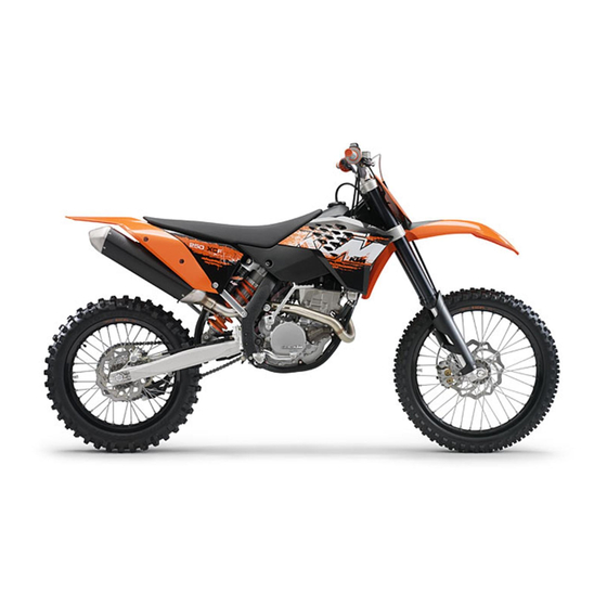
- Page 1 OWNER'S MANUAL 2011 250 EXC-F EU 250 EXC‑F Factory Edition EU 250 EXC-F AUS 250 EXC-F SIX DAYS EU 250 XCF‑W SIX DAYS USA Art. no. 3211689en...
- Page 3 KTM accepts no liability for delivery options, deviations from illustrations and descriptions, as well as misprints and other errors.
-
Page 4: Table Of Contents
TABLE OF CONTENTS Preparations for riding on dry sand ........25 TABLE OF CONTENTS MEANS OF REPRESENTATION ..........4 Preparations for riding on wet sand ......... 26 IMPORTANT INFORMATION ..........5 Preparing for rides on wet and muddy surfaces....27 VIEW OF VEHICLE............... - Page 5 TABLE OF CONTENTS Removing headlight mask with headlight ......78 Removing the shock absorber ........50 Refitting the headlight mask with the headlight....79 Installing the shock absorber ........51 Changing the headlight bulb........... 79 Removing the front fender ..........51 Checking the headlight adjustment .........
-
Page 6: Means Of Representation
All work marked with this symbol requires specialist knowledge and technical understanding. In the interest of your own safety, have these jobs done in an authorized KTM workshop! There, your motorcycle will be serviced optimally by specially trained experts using the specialist tools required. -
Page 7: Important Information
Warranty The work prescribed in the service schedule must be carried out by an authorized KTM workshop only and confirmed in the customer's service record and in the KTM dealer.net; otherwise, all warranty claims will be void. No warranty claim can be honored for damage resulting from manipulation and/or other changes to the vehicle. - Page 8 IMPORTANT INFORMATION Transport Note Danger of damage The parked vehicle may roll away or fall over. – Always place the vehicle on a firm and even surface. Note Fire hazard Some vehicle components become very hot when the vehicle is operated. – Do not park the vehicle near flammable or explosive substances.
-
Page 9: View Of Vehicle
VIEW OF VEHICLE View of the vehicle from the left front (example) 100882-10 Hand brake lever Clutch lever Filler cap Air filter box lid Fork compression adjustment Fuel tap Shift lever Side stand Chain guide... -
Page 10: View Of The Vehicle From The Right Rear (Example)
VIEW OF VEHICLE View of the vehicle from the right rear (example) 100883-10 Shock absorber, compression adjustment Light switch Throttle grip Fork rebound adjustment Shock absorber, rebound adjustment Level viewer, rear brake fluid Level viewer, engine oil Foot brake lever Kick starter... -
Page 11: Serial Numbers
SERIAL NUMBERS Chassis number The chassis number is stamped on the steering head on the right. 500127-10 Type label The type label is fixed to the front of the steering head. 500128-10 Key number (All EXC‑F models) The key number is stamped on the key strap. -
Page 12: Shock Absorber Part Number
SERIAL NUMBERS Shock absorber part number The shock absorber part number is stamped on the top of the shock absorber above the adjusting ring on the engine side. 500129-10... -
Page 13: Controls
CONTROLS Clutch lever The clutch lever is fitted on the left side of the handlebar. The clutch is hydraulically operated and self-adjusting. 600659-10 Choke (EXC‑F EU, EXC‑F Factory Edition, EXC‑F SIX DAYS) The choke lever is fitted on the left side of the handlebar. ... -
Page 14: Short Circuit Button (All Exc-F Models)
CONTROLS Short circuit button (All EXC‑F models) The short circuit button is fitted on the left side of the handlebar. Possible states in basic position – In this position, the ignition circuit is • Short circuit button closed, and the engine can be started. pressed –... -
Page 15: Electric Starter Button (Exc-F Aus)
CONTROLS Electric starter button (EXC‑F AUS) 5.11 The electric starter button is fitted on the right side of the handlebar. Possible states • Electric starter button in basic position pressed – In this position, the electric starter is actuated. •... -
Page 16: Speedometer Activation And Test
CONTROLS Speedometer activation and test 5.16 Activating the speedometer The speedometer is activated when one of the keys is pressed or an impulse comes from the wheel speed sensor. Display test For the function test of the display, all display segments light up briefly. 400313-01 WS (wheel size) After the display function test, the wheel size WS is displayed briefly. -
Page 17: Setting The Clock
CONTROLS Setting the clock 5.19 Condition The motorcycle is stationary. – Press the button briefly and repeatedly until CLK appears at the bottom right of the display. – Press the button for 3 - 5 seconds. The hour display flashes. –... -
Page 18: Querying The Lap Time
CONTROLS Querying the lap time 5.21 Info This function can be called only if lap times are measured. Condition The motorcycle is stationary. – briefly and repeatedly until LAP appears at the bottom right of Press the button the display. –... -
Page 19: Display Mode Speed/Clk (Clock)
CONTROLS Display mode SPEED/CLK (clock) 5.24 – Press the button briefly and repeatedly until CLK appears at the bottom right of the display. The time is displayed in CLK display mode. Press the button . No function Press the button . -
Page 20: Display Mode Speed/Tr2 (Trip Master 2)
CONTROLS Press the button Next display mode briefly. Display mode SPEED/TR2 (trip master 2) 5.28 – Press the button briefly and repeatedly until TR2 appears at the top right of the display. TR2 (trip master 2) runs constantly and counts up to 999.9. The displayed value can be set manually with the button and the button . -
Page 21: Display Mode Speed/S1 (Stop Watch 1)
CONTROLS Display mode SPEED/S1 (stop watch 1) 5.31 – Press the button briefly and repeatedly until S1 appears at the top right of the display. S1 (stop watch 1) displays the journey time on the basis of TR1 and continues when an impulse is received from the wheel speed sensor. -
Page 22: Opening Filler Cap
CONTROLS Table of conditions and menu activation Display The motorcycle is Menu can be acti- stationary. vated Display mode SPEED/CLK (clock) • Display mode SPEED/LAP (lap time) • Display mode SPEED/TR1 (trip master 1) • Display mode SPEED/TR2 (trip master 2) •... -
Page 23: Fuel Tap
CONTROLS Fuel tap 5.35 The fuel tap is on the left side of the fuel tank. Using tap handle on the fuel tap, you can open or close the supply of fuel to the carburetor. Possible states Fuel supply closed OFF – No fuel can flow from the tank to the carburetor. •... -
Page 24: Kick Starter
CONTROLS Kick starter 5.38 The kick starter is fitted on the right of the engine. The engine can be started with either the kick starter or the electric starter. The upper part of the kick starter can be swung out. Info Before riding, swing the upper part of the kick starter inwards towards the engine. -
Page 25: Locking The Steering (All Exc-F Models)
CONTROLS Locking the steering (All EXC‑F models) 5.42 Note Danger of damage The parked vehicle may roll away or fall over. – Always place the vehicle on a firm and even surface. – Park the vehicle. – Turn the handlebar as far as possible to the right. –... -
Page 26: Putting Into Operation
When using your motorcycle, remember that others may feel disturbed by excessive noise. – Make sure that the pre-delivery inspection work has been carried out by an authorized KTM workshop. You receive a delivery certificate and the service record at vehicle handover. -
Page 27: Running-In The Engine
PUTTING INTO OPERATION – Hold the handlebar firmly with both hands and keep your feet on the footrests when riding. – If you carry any baggage, make sure it is fixed firmly as close as possible to the center of the vehicle and ensure even weight dis- tribution between the front and rear wheels. -
Page 28: Preparations For Riding On Wet Sand
– Mount the dust cover for the air filter. Dust protection device for air filter (59006019000) Info Read the KTM PowerParts installation instructions. 600869-01 – Mount the dust cover for the air filter for sand. Sand protection device for air filter (59006022000) Info Read the KTM PowerParts installation instructions. -
Page 29: Preparing For Rides On Wet And Muddy Surfaces
Waterproofing device for air filter (59006021000) Info See the KTM PowerParts fitting instructions. – Adjust the carburetor jetting and settings. Info 600870-01 Your authorized KTM workshop has the recommended carburetor tuning set- tings. – Fit the steel sprocket. – Clean the motorcycle. ( p. 93) –... -
Page 30: Preparing For Rides At High Temperature And Slow Speed
Fit a waterproofing device on the air filter. Waterproofing device for air filter (59006021000) Info See the KTM PowerParts fitting instructions. – Adjust the carburetor jetting and settings. Info 600870-01 Your authorized KTM workshop has the recommended carburetor tuning set- tings. -
Page 31: Riding Instructions
RIDING INSTRUCTIONS Checks and maintenance before putting into operation Info Before every trip, check the condition of the vehicle and ensure that it is safe to operate. The vehicle must be in perfect technical condition when used. – Check the engine oil level. ( p. -
Page 32: Starting Up
Do not change into a low gear at high engine speed. The engine races and the rear wheel can lock up. Info If you hear unusual noises while riding, stop immediately, switch off the engine and contact an authorized KTM workshop. First gear is used for starting off or for steep inclines. -
Page 33: Stopping, Parking
RIDING INSTRUCTIONS – On sandy, wet or slippery surfaces, use the rear brake. – Braking should always be completed before you go into a bend. Change down to a lower gear appropriate to your road speed. – On long downhill stretches, use the braking effect of the engine. Change down one or two gears, but do not overstress the engine. In this way, you have to brake far less and the brakes do not overheat. - Page 34 RIDING INSTRUCTIONS – Fill the fuel tank with fuel up to measurement Guideline Measurement of 35 mm (1.38 in) Total fuel tank 9.2 l Super unleaded (ROZ 95 / RON 95 / capacity, approx. (2.43 US gal) PON 91) ( p.
-
Page 35: Service Schedule
(EXC‑F SIX DAYS, XCF‑W SIX DAYS) Final check: Check the vehicle for roadworthiness and take a test ride. • • • Make the service entry in KTM DEALER.NET and in the service record. • • • S1N: Once after one operating hour... -
Page 36: Maintenance Work (As An Additional Order)
SERVICE SCHEDULE Maintenance work (as an additional order) S10N S40A S80A • Change the front brake fluid. Change the rear brake fluid. • Change the foot brake cylinder seals. • Change the hydraulic clutch fluid. p. 62) • Grease the steering head bearing. p. -
Page 37: Tuning The Chassis
Caution Danger of accidents Disassembly of pressurized parts can lead to injury. – The shock absorber is filled with high density nitrogen. Adhere to the description provided. (Your authorized KTM workshop will be glad to help.) Info The low-speed setting can be seen during the slow to normal compression of the shock absorber. -
Page 38: Adjusting High-Speed Compression Damping Of The Shock Absorber
Caution Danger of accidents Disassembly of pressurized parts can lead to injury. – The shock absorber is filled with high density nitrogen. Adhere to the description provided. (Your authorized KTM workshop will be glad to help.) Info The high-speed setting can be seen during the fast compression of the shock absorber. -
Page 39: Measuring Rear Wheel Sag Unloaded
TUNING THE CHASSIS Measuring rear wheel sag unloaded – Raise the motorcycle with the lift stand. ( p. 42) – Measure the distance – as vertically as possible – between the rear axle and a fixed point, such as a mark on the side cover. –... -
Page 40: Adjusting The Spring Preload Of The Shock Absorber
Caution Danger of accidents Disassembly of pressurized parts can lead to injury. – The shock absorber is filled with high density nitrogen. Adhere to the description provided. (Your authorized KTM workshop will be glad to help.) Info Before changing the spring preload, make a note of the present setting, e.g., by measuring the length of the spring. -
Page 41: Checking Basic Setting Of Fork
TUNING THE CHASSIS Checking basic setting of fork 9.11 Info For various reasons, no exact riding sag can be determined for the forks. – As with the shock absorber, smaller differences in the rider's weight can be com- pensated by the spring preload. –... -
Page 42: Adjusting The Spring Preload Of The Fork
TUNING THE CHASSIS Info Turn clockwise to increase damping; turn counterclockwise to reduce damp- ing. Adjusting the spring preload of the fork 9.14 – Turn the adjusting screws counterclockwise all the way. Info Make the same adjustment on both fork legs. –... - Page 43 TUNING THE CHASSIS Info Position the left and right handlebar supports evenly. – Position the handlebars. Info Make sure cables and wiring are positioned correctly. – Position the handlebar clamps. Fit and evenly tighten the four screws Guideline Screw, handlebar clamp 20 Nm (14.8 lbf ft) Info...
-
Page 44: Service Work On The Chassis
SERVICE WORK ON THE CHASSIS Raising the motorcycle with the lift stand 10.1 Note Danger of damage The parked vehicle may roll away or fall over. – Always place the vehicle on a firm and even surface. – Raise the motorcycle at the frame underneath the engine. Lift stand (54829055000) The wheels should no longer touch the ground. -
Page 45: Loosening The Fork Protector
SERVICE WORK ON THE CHASSIS – Press the dust boots back into their normal position. – Remove excess oil. – Position the fork protection. ( p. 43) – Remove the motorcycle from the lift stand. ( p. 42) Loosening the fork protector 10.5 –... -
Page 46: Installing The Fork Legs
SERVICE WORK ON THE CHASSIS Installing the fork legs 10.8 – Position the fork legs. Info The upper milled groove in the fork leg must be flush with the top edge of the upper triple clamp. Position bleeder screws toward the front. ... -
Page 47: Installing The Fork Protector
SERVICE WORK ON THE CHASSIS Installing the fork protector 10.10 – Position the fork protection on the left fork leg. Mount and tighten screws Guideline Remaining screws, chassis 10 Nm (7.4 lbf ft) – Position the fork protection on the right fork leg. Mount and tighten the screws. Guideline Remaining screws, chassis 10 Nm (7.4 lbf ft) -
Page 48: Fully Tighten Screws . Guideline Screw, Top Triple Clamp M8
SERVICE WORK ON THE CHASSIS – Position the upper triple clamp with the steering. – Mount screw but do not tighten yet. – Position the clutch line, wiring harness and CDI control unit. Mount and tighten screws Guideline Remaining screws, chassis 10 Nm (7.4 lbf ft) 201470-11... -
Page 49: Removing The Lower Triple Clamp X (Exc-F Eu/Aus)
SERVICE WORK ON THE CHASSIS – Position the brake calipers. Mount and tighten screws Guideline Screw, front brake caliper 25 Nm Loctite ® 243™ (18.4 lbf ft) – Mount cable clip – Position the brake line, wiring harness and clamp. Mount and tighten screws ... -
Page 50: Nm (14.8 Lbf Ft)
SERVICE WORK ON THE CHASSIS – Position the upper triple clamp with the steering. – Mount screw but do not tighten yet. – Position the clutch line, wiring harness and CDI control unit. Mount and tighten screws Guideline Remaining screws, chassis 10 Nm (7.4 lbf ft) 500149-11... -
Page 51: Checking The Steering Head Bearing Play
Danger of accidents Unstable vehicle handling from incorrect steering head bearing play. – Adjust the steering head bearing play without delay. (Your authorized KTM workshop will be glad to help.) Info If the bike is ridden with play in the steering head bearing, the bearing and the bearing seats in the frame can become dam- aged over time. -
Page 52: Adjusting Play Of Steering Head Bearing (Exc-F Eu/Aus)
SERVICE WORK ON THE CHASSIS – Mount and tighten screw Guideline Screw, top steering stem 17 Nm Loctite ® 243™ (12.5 lbf ft) – Check the steering head bearing play. ( p. 49) Adjusting play of steering head bearing (EXC‑F EU/AUS) 10.17 –... -
Page 53: Installing The Shock Absorber
SERVICE WORK ON THE CHASSIS Installing the shock absorber 10.20 – Push splash protector to the side and position the shock absorber. Mount and tighten screw Guideline Screw, top shock absorber 80 Nm Loctite ® 2701 (59 lbf ft) –... -
Page 54: Mounting The Seat
SERVICE WORK ON THE CHASSIS Mounting the seat 10.24 – Hook in the front of the seat at the collar sleeve of the fuel tank, lower it at the rear and simultaneously push it forward. – Make sure that the seat is correctly locked in. –... -
Page 55: Installing The Air Filter
SERVICE WORK ON THE CHASSIS Installing the air filter 10.28 – Mount the clean air filter onto the air filter support. – Apply grease to the section of the air filter. Long-life grease ( p. 109) 301262-10 – Put in both parts together, position them and fix them with air filter holder ... -
Page 56: Installing The Main Silencer
SERVICE WORK ON THE CHASSIS – Disconnect spring – Remove screws and take off main silencer. 600681-11 Installing the main silencer 10.31 – Mount the main silencer. Mount and tighten screws Guideline Remaining screws, chassis 10 Nm (7.4 lbf ft) –... -
Page 57: Dismounting The Fuel Tank
SERVICE WORK ON THE CHASSIS (XCF‑W SIX DAYS) – Remove screws of connecting cap – Remove the connecting cap, perforated pipe and glass fiber yarn filling – Remove screws and end cap – Remove screws and take off spark arrestor with stuffing yarn ... -
Page 58: Installing The Fuel Tank
SERVICE WORK ON THE CHASSIS – Pull both spoilers to the side of the radiator bracket and take the fuel tank away upward. 600677-10 Installing the fuel tank 10.34 Danger Fire hazard Fuel is highly flammable. – Never refuel the vehicle near open flames or burning cigarettes, and always switch off the engine first. Be careful that no fuel is spilt, especially on hot vehicle components. -
Page 59: Checking For Chain Dirt Accumulation
SERVICE WORK ON THE CHASSIS Checking for chain dirt accumulation 10.35 – Check the chain for coarse dirt accumulation. » If the chain is very dirty: – Clean the chain. ( p. 57) 400678-01 Cleaning the chain 10.36 Warning Danger of accidents Oil or grease on the tires reduces their grip. –... -
Page 60: Adjusting The Chain Tension
SERVICE WORK ON THE CHASSIS » If the chain tension does not meet specifications: – Adjust the chain tension. ( p. 58) – Remove the motorcycle from the lift stand. ( p. 42) Adjusting the chain tension 10.38 Warning Danger of accidents Danger caused by incorrect chain tension. –... - Page 61 SERVICE WORK ON THE CHASSIS – Pull on the upper part of the chain with the specified weight Guideline Weight of chain wear measurement 10… 15 kg (22… 33 lb.) 0 0 A – Measure the distance of 18 chain links in the lower chain section. ...
-
Page 62: Adjusting The Chain Guide
SERVICE WORK ON THE CHASSIS – Check the chain guide for wear. Info Wear is visible on the front of the chain guide. » If the light part of the chain guide is worn: – Change the chain guide. 400985-01 –... -
Page 63: Adjusting The Basic Position Of The Clutch Lever
SERVICE WORK ON THE CHASSIS – Check the throttle cable routing. Both throttle cables must be routed to the carburetor side by side behind the handlebars and above the tank bearing. » If the throttle cable is not routed as specified: –... -
Page 64: Changing The Hydraulic Clutch Fluid
SERVICE WORK ON THE CHASSIS Info Clean up overflowed or spilt fluid immediately with water. Changing the hydraulic clutch fluid 10.44 Warning Skin irritation Brake fluid can cause skin irritation on contact. – Avoid contact with skin and eyes, and keep out of the reach of children. –... -
Page 65: Brakes
BRAKES Checking free travel of hand brake lever 11.1 Warning Danger of accidents Brake system failure. – If there is no free travel on the hand brake lever, pressure builds up in the front brake circuit. The front brake can fail due to overheating. -
Page 66: Checking The Brake Discs
Warning Danger of accidents Reduced braking effect caused by old brake fluid. – Change the brake fluid of the front and rear brake according to the service schedule. (Your authorized KTM workshop will be glad to help.) – Move the brake fluid reservoir mounted on the handlebar to a horizontal position. -
Page 67: Checking The Front Brake Linings
Warning Danger of accidents Reduced braking effect caused by old brake fluid. – Change the brake fluid of the front and rear brake according to the service schedule. (Your authorized KTM workshop will be glad to help.) Warning Environmental hazard Hazardous substances cause environmental damage. - Page 68 Warning Danger of accidents Reduced braking effect caused by old brake fluid. – Change the brake fluid of the front and rear brake according to the service schedule. (Your authorized KTM workshop will be glad to help.) Warning Danger of accidents Reduced braking efficiency due to oil or grease on the brake discs.
-
Page 69: Checking The Free Travel Of The Foot Brake Lever
BRAKES – Fit the brake linings, insert the bolt, and mount the locking split pins. – Operate the hand brake lever repeatedly until the brake linings are in contact with the brake disc and there is a pressure point. 100398-10 –... -
Page 70: Checking Rear Brake Fluid Level
Warning Danger of accidents Reduced braking effect caused by old brake fluid. – Change the brake fluid of the front and rear brake according to the service schedule. (Your authorized KTM workshop will be glad to help.) – Stand the vehicle upright. -
Page 71: Checking Rear Brake Linings
Warning Danger of accidents Reduced braking effect caused by old brake fluid. – Change the brake fluid of the front and rear brake according to the service schedule. (Your authorized KTM workshop will be glad to help.) Warning Danger of accidents Reduced braking efficiency due to oil or grease on the brake discs. - Page 72 BRAKES Info Never use DOT 5 brake fluid! This is based on silicone oil and is colored purple. Oil seals and brake lines are not designed for DOT 5 brake fluid. Avoid contact between brake fluid and painted parts. Brake fluid attacks paint! Use only clean brake fluid from a sealed container.
-
Page 73: Wheels, Tires
WHEELS, TIRES Removing front wheel 12.1 – Raise the motorcycle with the lift stand. ( p. 42) – Press the brake caliper by hand on to the brake disc in order to press back the brake pistons. Info Make sure when pushing back the brake pistons that you do not press the brake caliper against the spokes. -
Page 74: Removing The Rear Wheel
WHEELS, TIRES – Lift the front wheel into the fork, position it, and insert the wheel spindle. – Mount and tighten screw Guideline Screw, front wheel spindle M24x1.5 45 Nm (33.2 lbf ft) – Activate the hand brake lever multiple times until the brake linings are in contact with the brake disc. -
Page 75: Checking The Tire Condition
12.5 Info Only mount tires approved and/or recommended by KTM. Other tires could have a negative effect on riding behavior. The type, condition and air pressure of the tires all have an important impact on the riding behavior of the motorcycle. -
Page 76: Checking Tire Air Pressure
Danger of accidents Instable handling due to incorrect spoke tension. – Ensure that the spoke tension is correct. (Your authorized KTM workshop will be glad to help.) Info A loose spoke can cause wheel imbalance, which leads to more loose spokes in a short time. - Page 77 WHEELS, TIRES Torque wrench with various accessories in set (58429094000)
-
Page 78: Electrical System
– Do not discard batteries with the household trash. Dispose of a defective battery in an environmentally compatible manner. Give the battery to your KTM dealer or to a recycling center that accepts used batteries. Warning Environmental hazard Hazardous substances cause environmental damage. -
Page 79: Removing The Main Fuse
ELECTRICAL SYSTEM Info Even when there is no load on the battery, it still loses power steadily. The charge state and the type of charge are very important for the service life of the battery. Rapid recharging with a high charging current shortens the battery's service life. If the charging current, charging voltage and charging time are exceeded, electrolyte escapes through the safety valves. -
Page 80: Changing The Fuse Of The Radiator Fan (Exc-F Six Days, Xcf-W Six Days)
ELECTRICAL SYSTEM – Insert the main fuse. Fuse (58011109110) ( p. 102) Info A reserve fuse is located in the starter relay. Replace a burned-out fuse only by an equivalent fuse. – Replace the protection cover. – Install the air filter box lid. ( p. -
Page 81: Refitting The Headlight Mask With The Headlight
ELECTRICAL SYSTEM Refitting the headlight mask with the headlight 13.8 – Connect the electric plug connector 600702-11 – Position the headlight mask and fix it with the rubber band Info Ensure that the retaining lugs engage in the fender. –... -
Page 82: Checking The Headlight Adjustment
ELECTRICAL SYSTEM Checking the headlight adjustment 13.10 – Stand the vehicle upright on a horizontal surface in front of a light wall and make a 0 0 A mark at the height of the center of the low beam headlight. –... - Page 83 ELECTRICAL SYSTEM – Position locking cap and, using a coin, turn it clockwise all the way. – Press any button on the speedometer. The speedometer is activated. – Position the speedometer in the bracket. – Mount and tighten the screws with washers. –...
-
Page 84: Cooling System
COOLING SYSTEM Cooling system 14.1 Water pump in the engine circulates the coolant. The pressure resulting from the warming of the cooling system is regulated by a valve in radiator cap . This ensures that operating the vehicle at the specified coolant tem- ... -
Page 85: Draining The Coolant
COOLING SYSTEM Condition The engine is cold. – Stand the motorcycle upright on a horizontal surface. – Remove radiator cap. – Check the coolant level in the radiator. Coolant level above the radiator fins. 10 mm (0.39 in) » If the coolant level does not meet specifications: –... - Page 86 COOLING SYSTEM – Refit the radiator cap. – Make a short test ride. – Check the coolant level. ( p. 82)
-
Page 87: Tuning The Engine
TUNING THE ENGINE Checking the play in the throttle cable 15.1 – Move the handlebar to the straight-ahead position. Move the throttle grip back- wards and forwards to ascertain the play in the throttle cable. Play in throttle cable 3… 5 mm (0.12… 0.2 in) »... -
Page 88: Carburetor - Adjusting The Idle Speed
TUNING THE ENGINE Carburetor - adjusting the idle speed 15.4 – Screw in idle adjusting screw all the way and then turn it to the prescribed basic setting. Guideline Idle mixture adjusting screw (All EXC‑F models) Open 1.25 turns Idle mixture adjusting screw (XCF‑W SIX DAYS) Open 1.5 turns... -
Page 89: Emptying The Carburetor Float Chamber
TUNING THE ENGINE Emptying the carburetor float chamber 15.5 Danger Fire hazard Fuel is highly flammable. – Never refuel the vehicle near open flames or burning cigarettes, and always switch off the engine first. Be careful that no fuel is spilt, especially on hot vehicle components. Clean up spilt fuel immediately. –... - Page 90 TUNING THE ENGINE – Clean gear teeth of the shift lever and shift shaft. – Mount the shift lever on the shift shaft in the required position and engage the gearing. Info The range of adjustment is limited. The shift lever must not come into contact with any other vehicle compo- nents during the shift procedure.
-
Page 91: Service Work On The Engine
SERVICE WORK ON THE ENGINE Checking the engine oil level 16.1 – Stand the motorcycle upright on a horizontal surface. Condition The engine is cold. – Check the engine oil level. The engine oil level is at the bottom edge of level viewer ... -
Page 92: Cleaning The Oil Screens
SERVICE WORK ON THE ENGINE Cleaning the oil screens 16.4 Warning Danger of scalding Engine oil and gear oil get very hot when the motorcycle is ridden. – Wear appropriate protective clothing and safety gloves. In case of burns, rinse immediately with lukewarm water. Warning Environmental hazard Hazardous substances cause environmental damage. -
Page 93: Removing The Oil Filter
SERVICE WORK ON THE ENGINE Removing the oil filter 16.5 Warning Danger of scalding Engine oil and gear oil get very hot when the motorcycle is ridden. – Wear appropriate protective clothing and safety gloves. In case of burns, rinse immediately with lukewarm water. Warning Environmental hazard Hazardous substances cause environmental damage. -
Page 94: Filling Up With Engine Oil
SERVICE WORK ON THE ENGINE Filling up with engine oil 16.7 Info Too little engine oil or poor-quality engine oil results in premature wear to the engine. – Remove screw connection on the clutch cover and fill up with engine oil. ... -
Page 95: Cleaning, Care
CLEANING, CARE Cleaning the motorcycle 17.1 Note Material damage Damage and destruction of components by high-pressure cleaning equipment. – Never clean the vehicle with high-pressure cleaning equipment or a strong water-jet. The excessive pressure can penetrate electri- cal components, socket connects, throttle cables, and bearings, etc., and can damage or destroy these parts. Warning Environmental hazard Hazardous substances cause environmental damage. -
Page 96: Protection For Winter Operation
CLEANING, CARE Protection for winter operation 17.2 Info If you use the motorcycle in the winter, you can expect to encounter salt on the roads. Precautions need to be taken against road salt corrosion. If the vehicle has been used on salted roads, clean it with cold water. Warm water intensifies the effects of salt. –... -
Page 97: Storage
– Store the vehicle in a dry location that is not subject to large fluctuations in tem- perature. Info KTM recommends raising the motorcycle. – Raise the motorcycle with the lift stand. ( p. 42) – Cover the motorcycle with a porous sheet or blanket. Do not use non-porous materi- als since they prevent humidity from escaping, thus causing corrosion. -
Page 98: Troubleshooting
TROUBLESHOOTING Faults Possible cause Action – The engine cannot be cranked (elec- Operating error Go through the steps of starting the engine. tric starter) p. 29) – Battery discharged Recharge the battery. p. 76) – Check the charging voltage. – Check the closed current. - Page 99 TROUBLESHOOTING Faults Possible cause Action – Engine stalls or pops back into the The intake system has an air leak Check rubber sleeves and carburetor for tight- carburetor ness. – Engine overheats Coolant level low in cooling system Check the cooling system for leaks. –...
-
Page 100: Technical Data - Engine
TECHNICAL DATA - ENGINE Design 1-cylinder 4-stroke engine, water-cooled Displacement 248.60 cm³ (15.1706 cu in) Stroke 54.80 mm (2.1575 in) Bore 76 mm (2.99 in) Compression ratio 12.8:1 Idle speed 1,400… 1,500 rpm Control DOHC, four valves controlled via cam lever, drive via tooth-wheel chain Valve diameter, intake 30.0 mm (1.181 in) -
Page 101: Technical Data - Engine Tightening Torques
TECHNICAL DATA - ENGINE TIGHTENING TORQUES ® Oil jet, conrod lubrication 2 Nm (1.5 lbf ft) Loctite 243™ ® Oil jet for cam lever lubrication 4 Nm (3 lbf ft) Loctite 243™ ® Screw, freewheel hub 7 Nm (5.2 lbf ft) Loctite 243™... - Page 102 TECHNICAL DATA - ENGINE TIGHTENING TORQUES – Plug for oil screen, long M20x1.5 15 Nm (11.1 lbf ft) – Plug, timing chain tensioner M24x1.5 25 Nm (18.4 lbf ft)
-
Page 103: Technical Data - Carburetor
TECHNICAL DATA - CARBURETOR All EXC‑F models 22.1 Carburetor type KEIHIN FCR-MX 39 Carburetor identification number 3900H Needle position 3rd position from top Idle mixture adjusting screw Open 1.25 turns Pump diaphragm stop 2.15 mm (0.0846 in) Main jet Jet needle OBDYS (OBETP) Idling jet Idle air jet... -
Page 104: Technical Data - Chassis
TECHNICAL DATA - CHASSIS Frame Central tube frame made of chrome molybdenum steel tubing Fork WP Suspension Up Side Down 4860 MXMA PA Suspension travel Front 300 mm (11.81 in) Rear 335 mm (13.19 in) Fork offset (EXC‑F Factory Edition, EXC‑F SIX DAYS, 19 mm (0.75 in) XCF‑W SIX DAYS) Fork offset (EXC‑F EU/AUS) -
Page 105: Tires
80/100 - 21 51M TT 100/100 - 18 64M TT Bridgestone Bridgestone M59 Bridgestone Bridgestone M402 Additional information is available in the Service section under: http://www.ktm.com Capacity - fuel 23.3 Total fuel tank capacity, 9.2 l (2.43 US gal) Super unleaded (ROZ 95 / RON 95 / PON 91) ( p. -
Page 106: Technical Data - Fork
TECHNICAL DATA - FORK Fork part number 14.18.7J.04 Fork WP Suspension Up Side Down 4860 MXMA PA Compression damping Comfort 26 clicks Standard 22 clicks Sport 18 clicks Rebound damping Comfort 24 clicks Standard 20 clicks Sport 20 clicks Spring preload - Preload Adjuster Comfort 0 turn Standard... -
Page 107: Technical Data - Shock Absorber
TECHNICAL DATA - SHOCK ABSORBER Shock absorber part number 12.18.7J.04 Shock absorber WP Suspension PDS 5018 DCC Compression damping, low-speed Comfort 22 clicks Standard 20 clicks Sport 15 clicks Compression damping, high-speed Comfort 2 turns Standard 1.5 turns Sport 1.25 turns Rebound damping Comfort 26 clicks... -
Page 108: Technical Data - Tightening Torques For Chassis
TECHNICAL DATA - TIGHTENING TORQUES FOR CHASSIS – Spoke nipple, front wheel M4.5 5… 6 Nm (3.7… 4.4 lbf ft) – Screw, spoiler on fuel tank M5x12 1.5 Nm (1.11 lbf ft) (XCF‑W SIX DAYS) – Spoke nipple, rear wheel 5…... -
Page 109: Substances
– Guideline – Use only brake fluid that complies with the specified standard (see specifications on the container) and that possesses the corre- ® sponding properties. KTM recommends Castrol and Motorex products. Supplier Castrol – RESPONSE BRAKE FLUID SUPER DOT 4 ®... - Page 110 SUBSTANCES Super unleaded (ROZ 95 / RON 95 / PON 91) According to – DIN EN 228 (ROZ 95 / RON 95 / PON 91)
-
Page 111: Auxiliary Substances
AUXILIARY SUBSTANCES Air filter cleaner Guideline – ® KTM recommends Motorex products. Supplier ® Motorex – Twin Air Dirt Bio Remover Chain cleaner Guideline – ® KTM recommends Motorex products. Supplier ® Motorex – Chain Clean Cleaning and preserving materials for metal, rubber and plastic Guideline –... - Page 112 AUXILIARY SUBSTANCES Paint cleaner and polish for high-gloss and matte finishes, bare metal and plastic surfaces Guideline – ® KTM recommends Motorex products. Supplier ® Motorex – Clean & Polish Universal oil spray Guideline – ® KTM recommends Motorex products.
-
Page 113: Standards
STANDARDS JASO T903 MA Different technical development directions required a new specification for 4-stroke motorcycles – the JASO T903 MA Standard. Ear- lier, engine oils from the automobile industry were used for 4-stroke motorcycles because there was no separate motorcycle specifi- cation. -
Page 114: Index
INDEX fluid, changing ......62 INDEX Clutch lever ........11 Accessories . - Page 115 INDEX Fork protector installing ....... . . 45 Oil filter removing .
- Page 116 INDEX Spoke tension checking ....... . . 74 Spring preload fork, adjusting .
- Page 117 *3211689en* 3211689en KTM-Sportmotorcycle AG 5230 Mattighofen/Austria http://www.ktm.com...