Table of Contents
Advertisement
Quick Links
Advertisement
Table of Contents

Related Manuals for Asus Maximus VIII Hero


Summary of Contents for Asus Maximus VIII Hero
- Page 1 MAXIMUS VIII HERO...
- Page 2 Product warranty or service will not be extended if: (1) the product is repaired, modified or altered, unless such repair, modification of alteration is authorized in writing by ASUS; or (2) the serial number of the product is defaced or missing.
-
Page 3: Table Of Contents
Contents Safety information ...................... vi About this guide ......................vii MAXIMUS VIII HERO specifications summary............ix Package contents ..................... xiv Installation tools and components ................xv Chapter 1: Product Introduction Special features..................1-1 1.1.1 Product highlights................ 1-1 1.1.2 ROG Gaming Features ............... 1-3 1.1.3... - Page 4 3.6.12 Intel(R) ThunderBolt ..............3-37 Monitor menu ................... 3-38 Boot menu ....................3-43 Tool menu ....................3-48 3.9.1 ASUS EZ Flash 3 Utility ............3-48 3.9.2 Secure Erase ................3-48 3.9.3 ASUS Overclocking Profile ............3-50 3.9.4 ROG OC Panel H-Key Configure ..........3-51 3.9.5...
- Page 5 Dual Intelligent Processors 5 ..............4-6 ROG Audio features ................. 4-22 Sonic Radar II ................... 4-29 GameFirst III ..................... 4-31 KeyBot II....................4-34 4.10 ASUS Media Streamer ................4-36 4.11 RAMDisk ....................4-38 4.12 MemTweakIt ....................4-41 4.13 ROG CPU-Z ....................4-43 4.14...
-
Page 6: Safety Information
Safety information Electrical safety • To prevent electrical shock hazard, disconnect the power cable from the electrical outlet before relocating the system. • When adding or removing devices to or from the system, ensure that the power cables for the devices are unplugged before the signal cables are connected. If possible, disconnect all power cables from the existing system before you add a device. -
Page 7: About This Guide
Refer to the following sources for additional information and for product and software updates. ASUS website The ASUS website (www.asus.com) provides updated information on ASUS hardware and software products. Optional documentation Your product package may include optional documentation, such as warranty flyers, that may have been added by your dealer. -
Page 8: Conventions Used In This Guide
Conventions used in this guide To ensure that you perform certain tasks properly, take note of the following symbols used throughout this manual. DANGER/WARNING: Information to prevent injury to yourself when trying to complete a task. CAUTION: Information to prevent damage to the components when trying to complete a task IMPORTANT: Instructions that you MUST follow to complete a task. -
Page 9: Maximus Viii Hero Specifications Summary
Supports 14 nm CPU Supports Intel Turbo Boost Technology 2.0* ® * *Intel® Turbo Boost Technology 2.0 support depends on the CPU type * Refer to www.asus.com for Intel CPU support list Intel Z170 Express Chipset Chipset ® 4 x DIMM, max. 64GB, 3466(OC)* / 3400(OC)* / 3300(OC)* /... - Page 10 - Sonic Radar II - DTS Connect Intel Z170 Express Chipset - supports ASUS USB 3.1 Boost: ® - 4 x USB 3.0 ports (at mid-board [grey]) - 8 x USB 2.0 ports (4 ports at back panel, 4 ports at mid-board)* ASMedia USB 3.0 controller - supports ASUS USB 3.1 Boost:...
- Page 11 MAXIMUS VIII HERO specifications summary Extreme Engine Digi+ - MicroFine Alloy Choke - NexFET MOSFETs - 10K Black Metallic Capacitors OC Zone - LN2 Mode header - Start button - Reset button ROG RAMDisk ROG RAMCache ROG Overwolf ROG Exclusive Features...
- Page 12 1 x MemOK! button 1 x M.2 Socket 3 for M Key, type 2242/2260/2280/22110 storage devices support (Supports PCIE SSD and SATA Modes) 1 x Thunderbolt header (5-pin) for ASUS ThunderboltEX II series support 1 x Front panel audio connector (AAFP)
- Page 13 MAXIMUS VIII HERO specifications summary 1 x 128 Mb Flash ROM, UEFI AMI BIOS, PnP, DMI2.0, WfM2.0, SM BIOS 2.8, ACPI 5.1, Multi-language BIOS, ASUS EZ Flash 3, CrashFree BIOS 3, F11 EZ Tuning Wizard, F6 Qfan Control, F3 My...
-
Page 14: Package Contents
Package contents Check your motherboard package for the following items. ROG MAXIMUS VIII HERO Motherboard 3 x 2-in-1 SATA 6 Gb/s cables Cables 1 x SLI bridge ® 1 x I/O Shield 1 x 12-in-1 ROG cable label 1 x 2-in-1 Q-Connector kit... -
Page 15: Installation Tools And Components
Installation tools and components 1 Bag of screws Phillips (cross) screwdriver PC chassis Power supply unit Intel LGA 1151 CPU Intel LGA 1151 compatible CPU Fan DDR4 DIMM SATA hard disk drive SATA optical disc drive (optional) Graphics card (optional) The tools and components in the table above are not included in the motherboard package. -
Page 17: Chapter 1: Product Introduction
This motherboard supports multi-GPU SLI /CrossFireX graphics cards for an unrivalled ® gaming performance. With the Intel Z97 platform to optimize the PCIe allocation of multiple ® ™ GPUs, it supports up to 2-WAY GPU SLI or CrossFireX configuration. ® ASUS MAXIMUS VIII HERO... - Page 18 M.2 Support This motherboard features an M.2 slot, which supports both PCIE and SATA modes. The PCIE mode operates at full PCI Gen. 3.0 x4 speeds. The SATA mode shares bandwidth with SATA ports 1 and 2 and will automatically disable those ports when an M.2 card is inserted. Supports 2242 (22 mm x 42 mm), 2260 (22 mm x 60 mm), 2280 (22 mm x 80 mm), and 22110 (22 mm x 110 mm) SSD cards.
-
Page 19: Rog Gaming Features
GameFirst technology ASUS GameFirst technology is a network management software that features four preset packet prioritized profiles facilitating user’s need. Users can also manually allocate bandwidth and adjust priority settings of each application to run faster and smoother. -
Page 20: Rog Exclusive Features
USB 3.1 Boost ASUS USB 3.1 Boost, which supports USB 3.0 and USB 3.1 standard UASP (USB Attached SCSI Protocol), significantly increases a USB device’s transfer speed up to 170% faster than the already impressive USB 3.1 transfer speed. -
Page 21: Usb Bios Flashback
Consumers can connect their PC to a home theatre system. DTS Interactive is capable of performing multichannel encoding of DTS bitstreams on personal computers, and sending encoded bitstreams out of a digital audio connection (such as S/PDIF or HDMI) designed to deliver audio to an external decoder. ASUS MAXIMUS VIII HERO... -
Page 22: Motherboard Overview
Motherboard overview 1.2.1 Before you proceed Take note of the following precautions before you install motherboard components or change any motherboard settings. • Unplug the power cord from the wall socket before touching any component. • Before handling components, use a grounded wrist strap or touch a safely grounded object or a metal object, such as the power supply case, to avoid damaging them due to static electricity. -
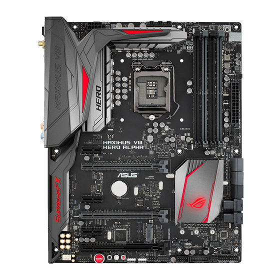
Page 23: Motherboard Layout
1.2.2 Motherboard layout Refer to Internal connectors and Rear I/O connection for more information about rear panel connectors and internal connectors. ASUS MAXIMUS VIII HERO... -
Page 24: Layout Contents
Layout contents Connectors/Jumpers/Buttons and switches/Slots Page 1. ATX power connectors (24-pin EATXPWR; 8-pin EATX12V) 1-37 2. LGA1151 CPU Socket 3. CPU, water pump, CPU optional, extension, and chassis fan connectors (4-pin CPU_FAN; 4-pin W_PUMP; 4-pin CPU_OPT; 5-pin EXT_FAN; 1-36 4-pin CHA_FAN1-4) 4. -
Page 25: Central Processing Unit (Cpu)
Contact your retailer immediately if the PnP cap is missing, or if you see any damage to the PnP cap/socket contacts/motherboard components. ASUS will shoulder the cost of repair only if the damage is shipment/ transit-related. -
Page 26: System Memory
1.2.4 System memory The motherboard comes with four Double Data Rate 4 (DDR4) Dual Inline Memory Modules (DIMM) slots. A DDR4 module is notched differently from a DDR, DDR2, or DDR3 module. DO NOT install a DDR, DDR2, or DDR3 memory module to the DDR4 slot. Recommended memory configurations Chapter 1: Product Introduction 1-10... -
Page 27: Memory Configurations
3.5 Ai Tweaker menu for manual memory frequency adjustment. • For system stability, use a more efficient memory cooling system to support a full memory load (4 DIMMs) or overclocking condition. ASUS MAXIMUS VIII HERO 1-11... - Page 28 MAXIMUS VIII HERO Motherboard Qualified Vendors Lists (QVL) DDR4 3466 MHz capability DIMM socket support Chip Chip Vendors Part No. Size Timing Voltage (Optional) Brand CORSAIR CMD16GX4M4B3466C18 16GB (4 x 4GB) 18-19-19-38 1.35V • • G.SKILL F4-3466C16Q-16GRRD 16GB (4 x 4GB) 16-18-18-38 1.35V...
- Page 29 16GB (4 x 4GB) 15-17-17-35 1.35V • • Kingston HX430C15PB2k4/16 16GB (4 x 4GB) 15-16-16-39 1.35V • • G.SKILL F4-3000C15Q-16GRR 16GB (4 x 4GB) 15-15-15-35 1.35V • • G.SKILL F4-3000C15Q-16GRK 16GB (4 x 4GB) 15-15-15-35 1.35V • • ASUS MAXIMUS VIII HERO 1-13...
- Page 30 DDR4 2800 MHz capability Vendors Part No. Size SS/DS Chip Chip NO. Timing Voltage DIMM Brand socket support (Optional) ADATA AX4U2800W4G17 32GB ( 8x 17-17-17-36 • • • 4GB ) ADATA AX4U2800W8G17 15-15-15-36 • • • Apacer 78.BAGM8.AF20B (XMP) 17-17-17-36 •...
- Page 31 ISDT I5AN4G8NMFR 15-15-15-35 • • (XMP) ISDT IMA451U6MFR8N-CF0 ISDT I5AN4G8NMFR 15-15-15-35 • • • (XMP) Team TCD44G2666C15ABK Samsung K4A4G085WD 15-15-15-35 • • • (XMP) Team TCD48G2666C15ABK 32GB(4x Team TCD48G2666C15ABK 15-15-15-35 • • • (XMP) 8GB) ASUS MAXIMUS VIII HERO 1-15...
- Page 32 DDR4 2400 MHz capability Vendors Part No. Size SS/DS Chip Chip NO. Timing Voltage DIMM Brand socket support (Optional) AVEXIR AVD4U24001608G-4M 32GB ( 8x SK Hynix H5AN4G8NMFRTFC 16-16-16-39 • • • 4GB ) CORSAIR CMD16GX4M4A2400C14 16GB ( 4x 14-16-16-31 • •...
- Page 33 ASUS exclusively provides hyper DIMM support function. • Hyper DIMM support is subject to the physical characteristics of individual CPUs. Load the X.M.P. settings in the BIOS for the hyper DIMM support. • Visit the ASUS website for the latest QVL. ASUS MAXIMUS VIII HERO 1-17...
-
Page 34: Expansion Slots
1.2.5 Expansion slots Unplug the power cord before adding or removing expansion cards. Failure to do so may cause you physical injury and damage motherboard components. Slot No. Slot Description PCIe 3.0 x1_1 slot PCIe 3.0 x16/x8_1 slot PCIe 3.0 x1_2 slot PCIe 3.0 x8_2 slot PCIe 3.0 x1_3 slot PCIe 3.0 x4_3 slot... -
Page 35: Irq Assignments For This Motherboard
Connect a chassis fan to the motherboard connector labeled CHA_FAN1-4 when using multiple graphics cards for better thermal environment. • New 6th generation Intel Core™ processors support PCIe 3.0 speed rate. ® PCIe_x16/x8_1 slot switches to x8 mode when PCIe_x8_2 slot is occupied. ASUS MAXIMUS VIII HERO 1-19... - Page 36 PCIe operating mode Motherboard Layout Modes PCIe PCIe Auto PCIEX1_1 – PCIE_X16/X8_1 – – – PCIEX1_2 – – PCIE_X8_2 – – – – PCIEX1_3 – – PCIEX4_3 • PCIEX4_3 shares bandwidth with PCIEX1_2 and PCIEX1_3. • PCIEX4_3 will run in X2 mode by default with PCIEX1_2 and PCIEX1_3 enabled. •...
-
Page 37: Onboard Buttons
The button also lights up when the system is plugged to a power source indicating that you should shut down the system and unplug the power cable before removing or installing any motherboard component. RESET button (RESET) Press the reset button to reboot the system. ASUS MAXIMUS VIII HERO 1-21... - Page 38 BIOS default settings. A message will appear during POST reminding you that the BIOS has been restored to its default settings. • We recommend that you download and update to the latest BIOS version from www.asus.com after using the MemOK! function. Chapter 1: Product Introduction 1-22...
- Page 39 Clear CMOS button (CLR_CMOS) Press this button to clear the BIOS setup information only when the systems hangs due to overclocking. ASUS MAXIMUS VIII HERO 1-23...
-
Page 40: Onboard Leds
1.2.7 Onboard LEDs Hard Disk LED (HD_LED) The Hard Disk LED is designed to indicate the hard disk activity. It blinks when data is being written into or read from the hard disk drive. The LED does not light up when there is no hard disk drive connected to the motherboard or when the hard disk drive does not function. - Page 41 Q-Code LED The Q-Code LED design provides you with a 2-digit error code that displays the system status. Refer to the Q-Code table on the following page for details. ASUS MAXIMUS VIII HERO 1-25...
- Page 42 Q-Code table Code Description Not used Power on. Reset type detection (soft/hard). AP initialization before microcode loading System Agent initialization before microcode loading PCH initialization before microcode loading Microcode loading AP initialization after microcode loading System Agent initialization after microcode loading PCH initialization after microcode loading Cache initialization 0C –...
- Page 43 Reserved for future AMI progress codes S3 Resume Failed S3 Resume PPI not Found S3 Resume Boot Script Error S3 OS Wake Error Reserved for future AMI error codes EC – EF (continued on the next page) ASUS MAXIMUS VIII HERO 1-27...
- Page 44 Q-Code table Code Description Recovery condition triggered by firmware (Auto recovery) Recovery condition triggered by user (Forced recovery) Recovery process started Recovery firmware image is found Recovery firmware image is loaded F5 – F7 Reserved for future AMI progress codes Recovery PPI is not available Recovery capsule is not found Invalid recovery capsule...
- Page 45 Legacy Boot event Exit Boot Services event Runtime Set Virtual Address MAP Begin Runtime Set Virtual Address MAP End Legacy Option ROM Initialization System Reset USB hot plug PCI bus hot plug (continued on the next page) ASUS MAXIMUS VIII HERO 1-29...
- Page 46 Q-Code table Code Description Clean-up of NVRAM Configuration Reset (reset of NVRAM settings) Reserved for future AMI codes B8– BF CPU initialization error System Agent initialization error PCH initialization error Some of the Architectural Protocols are not available PCI resource allocation error. Out of Resources No Space for Legacy Option ROM No Console Output Devices are found No Console Input Devices are found...
-
Page 47: Jumper
1.2.8 Jumper LN2 Mode jumper (3-pin LN2_MODE) With LN2 mode activated, the ROG motherboard is optimized to remedy the cold-boot bug during POST and help the system boot successfully. ASUS MAXIMUS VIII HERO 1-31... -
Page 48: Internal Connectors
1.2.9 Internal connectors Intel Z170 Serial ATA 6 Gb/s connectors (7-pin SATA6G_12; SATAEXPRESS12) ® These connectors connect to Serial ATA 6 Gb/s hard disk drives via Serial ATA 6 Gb/s signal cables. If you installed Serial ATA hard disk drives, you can create a RAID 0, 1, 5, and 10 configuration with the Intel Rapid Storage Technology through the onboard Intel ®... - Page 49 USB 3.0 ports under Windows 7, Windows 8, and ® ® Windows ® 8.1. • The plugged USB 3.0 device may run on xHCI or EHCI mode depending on the operating system’s setting. ASUS MAXIMUS VIII HERO 1-33...
- Page 50 Never connect a 1394 cable to the USB connectors. Doing so will damage the motherboard! You can connect the front panel USB cable to the ASUS Q-Connector (USB) first, and then install the Q-Connector (USB) to the USB connector onboard if your chassis supports front panel USB ports.
- Page 51 • If you want to connect a high-definition or an AC’97 front panel audio module to this connector, set the Front Panel Type item in the BIOS setup to [HD] or [AC97]. ASUS MAXIMUS VIII HERO 1-35...
- Page 52 CPU, water pump, CPU optional, extension, and chassis fan connectors (4-pin CPU_FAN; 4-pin W_PUMP; 4-pin CPU_OPT; 5-pin EXT_FAN; 4-pin CHA_FAN1-4) Connect the fan cables to the fan connectors on the motherboard, ensuring that the black wire of each cable matches the ground pin of the connector. •...
- Page 53 • If you are uncertain about the minimum power supply requirement for your system, refer to the Recommended Power Supply Wattage Calculator at http://support.asus. com/PowerSupplyCalculator/PSCalculator.aspx?SLanguage=en-us for details. ASUS MAXIMUS VIII HERO 1-37...
-
Page 54: System Panel Connector
System panel connector (20-5 pin PANEL) This connector supports several chassis-mounted functions. • System power LED (3-1 pin or 2-pin PLED) This 3-1 pin or 2-pin connector is for the system power LED. Connect the chassis power LED cable to this connector. The system power LED lights up when you turn on the system power, and blinks when the system is in sleep mode. - Page 55 • The OC Panel and Front Base are purchased separately. • Visit www.asus.com for more information about the OC Panel and Front Base. TPM connector (14-1 pin TPM) This connector supports a Trusted Platform Module (TPM) system, which securely store keys, digital certificates, passwords and data. A TPM system also helps enhance the network security, protects digital identities, and ensures platform integrity.
- Page 56 T_Sensor connector (2-pin T_SENSOR1) This connector is for the thermistor cable that allows you to monitor the temperature of your motherboard’s critical components and connected devices. M.2 (Socket 3) The M.2 (Socket 3) with M Key supports type 2242 (22mm x 42mm), 2260 (22mm x 60mm), 2280 (22mm x 80mm), and 22110 (22mm x 110mm) PCIe/SATA interface storage devices.
- Page 57 This connector is for the add-on Thunderbolt I/O card that supports Intel’s Thunderbolt Technology, allowing you to connect up to six Thunderbolt-enabled devices and a DisplayPort-enabled display in a daisy-chain configuration. The add-on Thunderbolt I/O card and Thunderbolt cables are purchased separately. ASUS MAXIMUS VIII HERO 1-41...
- Page 58 Chapter 1: Product Introduction 1-42...
-
Page 59: Chapter 2: Basic Installation
The diagrams in this section are for reference only. The motherboard layout may vary with models, but the installation steps are the same for all models. Install the ASUS Q-Shield to the chassis rear I/O panel. Place the motherboard into the chassis, ensuring that its rear I/O ports are aligned to the chassis’... - Page 60 Place nine screws into the holes indicated by circles to secure the motherboard to the chassis. DO NOT over tighten the screws! Doing so can damage the motherboard. Chapter 2: Basic Installation...
-
Page 61: Cpu Installation
Ensure that you install the correct CPU designed for LGA1151 socket only. DO NOT install a CPU designed for LGA1155 and LGA1156 sockets on the LGA1151 socket. Top of CPU Bottom of CPU Bottom of CPU ASUS MAXIMUS VIII HERO... - Page 62 Top of CPU WARNING! • Ensure that the CPU is firmly clicked into place before installing it onto the CPU socket on the motherboard. • Use the CPU Installation Tool for installing the CPU only. DO NOT damage or bend the CPU Installation Tool. • Always firmly hold both sides of the CPU Installation Tool when installing, removing, or picking up the CPU Installation Tool. • ASUS will not cover damages resulting from incorrect CPU installation/removal, incorrect CPU orientation/placement, or other damages resulting from negligence by the user. Chapter 2: Basic Installation...
-
Page 63: Cpu Heatsink And Fan Assembly Installation
2.1.3 CPU heatsink and fan assembly installation Apply the Thermal Interface Material to the CPU heatsink and CPU before you install the heatsink and fan, if necessary. To install the CPU heatsink and fan assembly ASUS MAXIMUS VIII HERO... - Page 64 To uninstall the CPU heatsink and fan assembly Chapter 2: Basic Installation...
-
Page 65: Dimm Installation
2.1.4 DIMM installation To remove a DIMM ASUS MAXIMUS VIII HERO... -
Page 66: Atx Power Connection
2.1.5 ATX Power connection Chapter 2: Basic Installation... -
Page 67: Sata Device Connection
2.1.6 SATA device connection ASUS MAXIMUS VIII HERO... -
Page 68: Front I/O Connector
2.1.7 Front I/O Connector To install ASUS Q-Connector To install USB 2.0 connector To install front panel audio connector AAFP USB 2.0 To install USB 3.0 connector USB 3.0 Chapter 2: Basic Installation 2-10... -
Page 69: Expansion Card Installation
2.1.8 Expansion Card installation To install PCIe x16 cards ASUS MAXIMUS VIII HERO 2-11... -
Page 70: Usb Bios Flashback
For more BIOS update utilities in BIOS setup, refer to the section Updating BIOS in Chapter 3. • Connect your USB keyboard on the KeyBot port if you want to use the KeyBot feature. Updating BIOS may have risks. If the BIOS program is damaged during the process and results to the system’s failure to boot up, please contact your local ASUS Service Center. Chapter 2: Basic Installation 2-12... -
Page 71: Motherboard Rear And Audio Connections
USB 3.0 ports 5 and 6 ® 11. Optical S/PDIF OUT port 12. Audio I/O ports** * and ** : Refer to the tables on the next page for LAN port LEDs, and audio port definitions. ASUS MAXIMUS VIII HERO 2-13... -
Page 72: Audio I/O Connections
• Due to USB 3.0 controller limitation, USB 3.0 devices can only be used under Windows 7 and after the USB 3.0 driver installation. ® • USB 3.0 devices can only be used as data storage only. • We strongly recommend that you connect USB 3.0 devices to USB 3.0 ports for faster and better performance for your USB 3.0 devices. • Due to the design of the Intel chipset, all USB devices connected to the USB 2.0 and USB 3.0 ports are controlled by the xHCI controller. Some legacy USB devices must update their firmware for better compatibility. - Page 73 Connect to Headphone and Mic Connect to Stereo Speakers Connect to 2.1 channel Speakers ASUS MAXIMUS VIII HERO 2-15...
- Page 74 Connect to 4.1 channel Speakers Connect to 5.1 channel Speakers Connect to 7.1 channel Speakers Chapter 2: Basic Installation 2-16...
-
Page 75: Starting Up For The First Time
While the system is ON, press the power button for less than four seconds to put the system on sleep mode or soft-off mode, depending on the BIOS setting. Press the power button for more than four seconds to let the system enter the soft-off mode regardless of the BIOS setting. ASUS MAXIMUS VIII HERO 2-17... - Page 76 Chapter 2: Basic Installation 2-18...
-
Page 77: Chapter 3: Bios Setup
BIOS Setup Knowing BIOS The new ASUS UEFI BIOS is a Unified Extensible Interface that complies with UEFI architecture, offering a user-friendly interface that goes beyond the traditional keyboard- only BIOS controls to enable a more flexible and convenient mouse input. You can easily navigate the new UEFI BIOS with the same smoothness as your operating system. -
Page 78: Bios Setup Program
BIOS setup program Use the BIOS Setup to update the BIOS or configure its parameters. The BIOS screen include navigation keys and brief onscreen help to guide you in using the BIOS Setup program. Entering BIOS at startup To enter BIOS Setup at startup, press <Delete> during the Power-On Self Test (POST). If you do not press <Delete>, POST continues with its routines. -
Page 79: Ez Mode
Click to go to Advanced mode Search on the FAQ Loads optimized default settings Click to display boot devices Selects the boot device priority The boot device options vary depending on the devices you installed to the system. ASUS MAXIMUS VIII HERO... -
Page 80: Advanced Mode
3.2.2 Advanced Mode The Advanced Mode provides advanced options for experienced end-users to configure the BIOS settings. The figure below shows an example of the Advanced Mode. Refer to the following sections for the detailed configurations. To switch from EZ Mode to Advanced Mode, click Advanced Mode(F7) or press the <F7> hotkey. -
Page 81: Menu Bar
EZ Tuning Wizard(F11) This button above the menu bar allows you to view and tweak the overclocking settings of your system. It also allows you to change the motherboard’s SATA mode from AHCI to RAID mode. ASUS MAXIMUS VIII HERO... -
Page 82: Hot Keys
Quick Note (F9) This button above the menu bar allows you to key in notes of the activities that you have done in BIOS. • The quick Note function does not support the following keyboard functions: delete, cut, copy and paste. •... -
Page 83: My Favorites
You cannot add the following items to My Favorite items: • Items with sub-menu options. • User-managed items such as language and boot order. • Configuration items such as Memory SPD Information, system time and date. ASUS MAXIMUS VIII HERO... -
Page 84: Main Menu
Main menu The Main menu screen appears when you enter the Advanced Mode of the BIOS Setup program. The Main menu provides you an overview of the basic system information, and allows you to set the system date, time, language, and security settings. Chapter 3: BIOS Setup... - Page 85 RTC RAM via the Clear CMOS button. • The Administrator or User Password items on top of the screen show the default [Not Installed]. After you set a password, these items show [Installed]. ASUS MAXIMUS VIII HERO...
-
Page 86: Administrator Password
Administrator Password If you have set an administrator password, we recommend that you enter the administrator password for accessing the system. Otherwise, you might be able to see or change only selected fields in the BIOS setup program. To set an administrator password: Select the Administrator Password item and press <Enter>. -
Page 87: Extreme Tweaker Menu
(X.M.P.) Technology, choose this item to set the profiles supported by your memory modules for optimizing the system performance. The [X.M.P.] configuration option appears only when you install memory modules supporting the eXtreme Memory Profile(X.M.P.) Technology. ASUS MAXIMUS VIII HERO 3-11... - Page 88 Configuration options: [Auto] [Disable] [32us/MHz] [64us/MHz] [128us/MHz] [512us/MHz] ASUS MultiCore Enhancement [Auto] [Auto] This item allows you to maximize the oveclocking performance optimized by ASUS core ratio settings. [Disabled] This item allows you to set to default core ratio settings. CPU Core Ratio [Auto] This item allows you to set the CPU core ratio limit per core or synchronize automatically to all cores.
- Page 89 The BCLK frequency to DRAM frequency ratio will be set to 100:100. DRAM Odd ratio Mode [Enabled] This item allows you to enable, disable or automatically set the odd ratio to provide better granularity. Configuration options: [Disabled] [Enabled] ASUS MAXIMUS VIII HERO 3-13...
- Page 90 Ensure to use water cooling device before selecting [TPU II]. EPU Power Saving Mode [Disabled] The ASUS EPU (Energy Processing Unit) sets the CPU in its minimum power consumption settings. Enable this item to set lower CPU core/cache voltage and achieve the best energy saving condition.
- Page 91 CPU and VRM thermal conditions. Select from levels 1 to 8 to adjust the CPU power voltage from 0% to 100%. Configuration options [Auto] [Level 1] - [Level 8] ASUS MAXIMUS VIII HERO 3-15...
- Page 92 The actual performance boost may vary depending on your CPU specification. DO NOT remove the thermal module. The thermal conditions should be monitored. CPU Current Capability [Auto] This item provides a total power range for CPU overclocking. A higher value setting provides higher power consumption delivery and extends the overclocking frequency range simultaneously.
- Page 93 Configuration options: [Auto] [100%] [110%] [120%] [130%] [140%] Configure higher values when overclocking or under a high GT loading for extra power support. ASUS MAXIMUS VIII HERO 3-17...
- Page 94 CPU Graphics [Auto] The switching frequency will affect the GT transient response speed and the component thermal production. Configuration options: [Auto] [Manual] DO NOT remove the thermal module. The thermal conditions should be monitored. The following item appears only when you set the CPU Graphics to [Manual]. CPU Graphics Frequency (KHz) [500] This item allows you to set a higher frequency for a quicker transient response speed.
- Page 95 Configuration options: [Enabled] [Disabled] Turbo Mode [Enabled] Allows you to enable your processor cores to run faster than the base operating frequency when it is below power, current and specification limit. Configuration options: [Disabled] [Enabled] ASUS MAXIMUS VIII HERO 3-19...
- Page 96 The following items appear only when you set the Turbo Mode to [Enabled]. Turbo Mode Parameters Long Duration Package Power Limit [Auto] Allows you to limit the Turbo Ratio’s time duration that exceeds the TDP (Thermal Design Power) for maximum performance. Use the <+> and <-> keys to adjust the value.
- Page 97 This item allows you to configure the CPU core voltage offset value. Configuration options: [0.250] - [1.920] Offset Voltage [Auto] This item allows you to configure the CPU core voltage offset value. Configuration options: [Auto] [0.001] - [0.999] ASUS MAXIMUS VIII HERO 3-21...
- Page 98 DRAM Voltage [Auto] Configuration options: [Auto] [1.0000] - [2.0000] DRAM VTT Voltage [Auto] Configuration options: [Auto] [0.500] - [1.300] VPPDDR Voltage [Auto] Configuration options: [Auto] [1.86500] - [3.13500] DMI Voltage [Auto] Configuration options: [Auto] [0.30000] - [1.90000] CPU VCCIO Voltage [Auto] Configuration options: [Auto] [0.70000] - [1.80000] CPU System Agent Voltage [Auto] Configuration options: [Auto] [0.70000] - [1.80000]...
-
Page 99: Advanced Menu
The Advanced menu items allow you to change the settings for the CPU and other system devices. Be cautious when changing the settings of the Advanced menu items. Incorrect field values can cause the system to malfunction. ASUS MAXIMUS VIII HERO 3-23... -
Page 100: Cpu Configuration
3.6.1 CPU Configuration The items in this menu show the CPU-related information that the BIOS automatically detects. The items in this menu may vary based on the CPU installed. Active Processor Cores [All] This item allows you to select the number of CPU cores to activate in each processor package. - Page 101 This item allows you to set the a C-state limit for the CPU package. Configuration options: [C0/C1] [C2] [C3] [C6] [C7] [C7s] [Auto] CFG Lock [Enabled] This item allows you to disable or enable the CFG Lock. Configuration options: [Enabled] [Disabled] ASUS MAXIMUS VIII HERO 3-25...
-
Page 102: Platform Misc Configuration
3.6.2 Platform Misc Configuration The items in this menu allow you to configure the platform-related features. PCI Express Native Power Management [Disabled] Enable this item to enhance the PCI-E power saving condition. Configuration options: [Disabled] [Enabled] The following item appears only when you set the PCI Express Native Power Management to [Enabled]. - Page 103 This item is for the control of the Active State Power Management on SA side of the DMI link. Configuration options: [Disabled] [L1] PEG ASPM [Disabled] This item is for the control of the Active State Power Management for the PEG 0. Configuration options: [Disabled] [Auto] [ASPM L0s] [L1] [L0sL1] ASUS MAXIMUS VIII HERO 3-27...
-
Page 104: System Agent (Sa) Configuration
3.6.3 System Agent (SA) Configuration VT-d [Enabled] Allows you to enable virtualization technology function on memory control hub. Configuration options: [Enabled] [Disabled] Graphics Configuration Allows you to select a primary display from graphical devices. Primary Display [Auto] [Auto] The primary display will be set to PCI-E when a PCI-E graphic card is detected. -
Page 105: Rog Effects
PCH (Logo) LED [Enabled] [Enabled] LEDs will always light up at the S0(Working), S3(Sleep), and S5(Soft off) states, but not light up at the S5 state when the “ErP Ready” is enabled. [Disabled] LEDs will not light up. ASUS MAXIMUS VIII HERO 3-29... -
Page 106: Pch Configuration
3.6.5 PCH Configuration PCI Express Configuration This item allows you to configure the PCI Express slots. PCI-E Speed [Auto] This item allows your system to automatically select the PCI Express port speed. When set to [Gen1], the PCI-E port runs at PCI-E 1.0 speed. When set to [Gen2], the PCI-E port runs at PCI-E 2.0 speed. - Page 107 Configuration options: [Disabled] [Enabled] Hot Plug [Disabled] These items appears only when the SATA Mode Selection is set to [AHCI] and allows you to enable or disable SATA Hot Plug Support. Configuration options: [Disabled] [Enabled] ASUS MAXIMUS VIII HERO 3-31...
-
Page 108: Usb Configuration
3.6.7 USB Configuration The items in this menu allow you to change the USB-related features. The USB Devices item shows the auto-detected values. If no USB device is detected, the item shows None. Legacy USB Support [Enabled] [Disabled] The USB devices can be used only for the BIOS setup program. It cannot be recognized in boot devices list. -
Page 109: Network Stack Configuration
Configuration options: [Disabled] [Enabled] The following items appear only when you set the Network Stack to [Enabled]. Ipv4/Ipv6 PXE Support [Enabled] This item allows you to enable or disable the Ipv4/Ipv6 PXE boot option. Configuration options: [Disabled] [Enabled] ASUS MAXIMUS VIII HERO 3-33... -
Page 110: Onboard Devices Configuration
3.6.9 Onboard Devices Configuration Scroll down to view the other BIOS items. HD Audio Controller [Enabled] [Disabled] HDA will be unconditionally disabled [Enabled] HDA will be unconditionally enabled PCIEX4_3 Slot(black) Bandwidth [Auto] [Auto] X2 mode PCIeX4_3; X1 mode PCIeX1_2 and PCIeX1_3 [X4 Mode] X4 mode Asmedia USB 3.1 Controller(USB3.1_E12) [Enabled]... - Page 111 Intel LAN PXE Option ROM [Disabled] This item appears only when Intel LAN Controller is set to [Enabled].This item allows you to enable or disable the Intel LAN preboot execution environment (PXE) option ROM. Configuration options: [Enabled] [Disabled] ASUS MAXIMUS VIII HERO 3-35...
-
Page 112: Apm Configuration
3.6.10 APM Configuration ErP Ready [Disabled] Allows you to switch off some power at S4+S5 or S5 to get the system ready for ErP requirement. When set to [Enabled], all other PME options will be switched off. Configuration options: [Disabled] [Enabled(S4+S5] [Enabled(S5)] Restore AC Power Loss [Power Off] [Power Off] The system goes into OFF state after an AC power loss. -
Page 113: Hdd Smart Information
This item allows you to disable or enable the Intel Thunderbolt Technology. Configuration options: [Fully Disabled] [Disabled] [Enabled] ThunderBolt Boot Support [Disabled] This item allows you to disable or enable the ThunderBolt Boot Support. Configuration options: [Disabled] [Enabled] ASUS MAXIMUS VIII HERO 3-37... -
Page 114: Monitor Menu
Monitor menu The Monitor menu displays the system temperature/power status, and allows you to change the fan settings. Q-Fan Configuration Qfan Tuning Click this item to automatically detect the lowest speed and configure the minimum duty cycle for each fan. CPU Q-Fan Control [Auto] [Auto] Detect the type of CPU fan installed and automatically switches the... - Page 115 The assignment fan will be controlled according to the selected temperature source. Configuration options: [CPU] [MotherBoard] [VRM] [PCH] [T_SENSOR1] [EXT_ Sensor1] [EXT_Sensor2] [EXT_Sensor3] For EXT_Sensor1-3, connect a Thermistor cable to the EXT_TS1-3 header then place the other end to the component to get the temperature. ASUS MAXIMUS VIII HERO 3-39...
- Page 116 Chassis Fan 1-4 Step Up [0 sec] This item allows you to set the value of the CPU fan step up. Configuration options: [0 sec] [12 sec] [25 sec] [51 sec] [76 sec] [102 sec] [127 sec] [153 sec] [178 sec] [204 sec] Chassis Fan 1-4 Step Down [0 sec] This item allows you to set the value of the CPU fan step down.
- Page 117 The values range from 0% to 100%. When the CPU temperature is under the limit, the Chassis Fan 1-4 fan will operate at the minimum duty cycle. ASUS FAN EXTENSION CARD is required to configure these items Extension Fan 1-4 Q-Fan Control [DC Mode] [Disabled] Disable the Extension Fan Q-Fan control feature.
- Page 118 Extension Fan 1-4 Middle. Duty Cycle (%) [60] Use the <+> or <-> keys to adjust the middle Extension Fan 1-4 duty cycle. The values range from 20% to 100%. When the CPU temperature reaches the middle limit, the Extension Fan 1-4 will operate at the middle duty cycle. Extension Fan 1-4 Lower Temperature [40] Use the <+>...
-
Page 119: Boot Menu
POST. This process extends the POST time. [HDD Only] Only hard drives connected to SATA ports are detected during POST. [Last Boot HDD Only] Only boot drives connected to a SATA ports are detected during POST. ASUS MAXIMUS VIII HERO 3-43... - Page 120 USB Support [Partial Initial] [Disabled] All USB devices will not be available until OS boot up for a fastest POST time. [Full Initial] All USB devices will be available during POST. This process will extend the POST time. [Partial Initial] For a faster POST time, only USB ports with keyboard and mouse connections will be detected.
- Page 121 Configuration options: [Disabled] [Enabled] Option ROM Messages [Enabled] [Enabled] The Option ROM Messages will be shown during the POST. [Disabled] Only the ASUS logo will be shown during the POST. Interrupt 19 Capture [Disabled] [Enabled] Execute the trap right away. [Disabled] Execute the trap during legacy boot.
-
Page 122: Secure Boot
Boot from PCI-E/PCI Expansion Devices [Legacy only] This item allows you to select the type of PCI-E/PCI expansion devices that you want to launch. Configuration options: [Legacy only] [UEFI driver first] Secure Boot This item allows you to configure the Windows Secure Boot settings and manage its keys to ®... -
Page 123: Boot Option Priorities
® ® • To access Windows OS in Safe Mode, press <F8> after POST (Windows 8 not supported). • To select the boot device during system startup, press <F8> when the ASUS Logo appears. ASUS MAXIMUS VIII HERO 3-47... -
Page 124: Boot Override
3.9.1 ASUS EZ Flash 3 Utility Allows you to run ASUS EZ Flash 3. When you press <Enter>, a confirmation message appears. Use the Left/Right arrow key to select between [by USB] or [by Internet], then press <Enter> to confirm your choice. - Page 125 Check the ASUS support site for a full list of SSDs tested with Secure Erase. The drive may become unstable if you run Secure Erase on an incompatible SSD. • The time to erase the contents of your SSD may take a while depending on its size.
-
Page 126: Asus Overclocking Profile
3.9.3 ASUS Overclocking Profile This item allows you to store or load multiple BIOS settings. Profile Name Key in the profile name to save current BIOS settings to profile 1 to 8. Save to Profile Saves the current BIOS settings to profile number 1 to 8. -
Page 127: Rog Oc Panel H-Key Configure
This item allows you to save the new values of the CPU Core Voltage, VCCSA Voltage, BCLK Frequency, and CPU Ratio. Load from profile This item allows you to load the previous values of the CPU Core Voltage, VCCSA Voltage, BCLK Frequency, and CPU Ratio. ASUS MAXIMUS VIII HERO 3-51... -
Page 128: Asus Spd Information
3.9.5 ASUS SPD Information Allows you to view the DRAM SPD information. DIMM slot number Allows you to select the DIMM slot number to show the plugged DRAM Serial Presence Detect (SPD) information. Configuration options: [DIMM_A1] [DIMM_A2] [DIMM_B1] [DIMM_B2] Some DRAM manufacturers may not be recognized. -
Page 129: Exit Menu
<Esc>, a confirmation window appears. Select Yes to discard changes and exit. Launch EFI Shell from filesystem device This option allows you to attempt to launch the EFI Shell application (shellx64.efi) from one of the available filesystem devices. ASUS MAXIMUS VIII HERO 3-53... -
Page 130: Updating Bios
® ASUS EZ Flash 3: Updates the BIOS using a USB flash drive. ASUS CrashFree BIOS 3: Restores the BIOS using the motherboard support DVD or a USB flash drive when the BIOS file fails or gets corrupted. ASUS BIOS Updater: Updates the BIOS in DOS environment using the motherboard support DVD and a USB flash disk drive. - Page 131 3.11.2 ASUS EZ Flash 3 Utility ASUS EZ Flash 3 Utility allows you to update the BIOS without having to use a bootable floppy disk or an OS-based utility. Before you start using this utility, download the latest BIOS from the ASUS website at http://www.asus.com.
-
Page 132: Asus Crashfree Bios
The BIOS file in the motherboard support DVD may be older than the BIOS file published on the ASUS official website. If you want to use the newer BIOS file, download the file at http://support.asus.com and save it to a USB flash drive. -
Page 133: Asus Bios Updater
3.11.4 ASUS BIOS Updater ASUS BIOS Updater allows you to update the BIOS in DOS environment. The screen captures used in this section are for reference only and may not be exactly the same as actually shown on your computer screen. - Page 134 On the BIOS Updater screen, press <Tab> to switch from Files panel to Drives panel then select D:. ASUSTeK BIOS Updater for DOS V1.30 [2014/01/01] Current ROM Update ROM BOARD: MAXIMUS VIII HERO BOARD: Unknown VER: 0210 (H :00 B :00)
- Page 135 DO NOT shut down or reset the system while updating the BIOS to prevent system boot failure. Ensure to load the BIOS default settings to ensure system compatibility and stability. Select the Load Optimized Defaults item under the Exit BIOS menu. See section 3.10 Exit menu for details. ASUS MAXIMUS VIII HERO 3-59...
- Page 136 Chapter 3: BIOS Setup 3-60...
-
Page 137: Chapter 4: Software Support
Running the support DVD Ensure that you have an Administrator account before running the support DVD in Windows 7, Windows 8, or Windows 8.1 OS. ® ® ® To run the support DVD Place the Support DVD into the optical drive. 2. In the AutoPlay dialog box, click Run ASSETUP.exe. If Autorun is NOT enabled in your computer, browse the contents of the support DVD to locate the file SETUP.EXE from the BIN folder. Double-click the ASSETUP.EXE to run the support DVD. ASUS MAXIMUS VIII HERO... -
Page 138: Obtaining The Software Manuals
Click to display product related information. Click to select an item to install Contains ROG related videos. Click to display the ASUS contact information. Click to install the selected items 4.2.2 Obtaining the software manuals The software manuals are included in the support DVD. Follow the instructions below to get the necessary software manuals. -
Page 139: Software Information
AI Suite 3 AI Suite 3 is an all-in-one interface that integrates several ASUS utilities and allows you to launch and operate these utilities simultaneously. Installing AI Suite 3 Ensure that you have an Administrator account before installing AI Suite 3 in Windows 7, ® Windows ® 8, or Windows ® 8.1 OS. To install AI Suite 3 on your computer: Windows 7 OS ® Place the Support DVD into the optical drive. 2. In the AutoPlay dialog box, click Run ASSETUP.exe then select the Utilities tab 3. From the Utilities tab, check AI Suite 3 and select Install, then follow the succeeding onscreen instructions. ASUS MAXIMUS VIII HERO... - Page 140 If the ASUS motherboard support DVD main menu did not appear, try the following steps: Go to the Start Screen then click the Desktop app. On the lower left corner of the Desktop, click File Explorer then select your DVD drive and double-click the Setup application. Launching AI Suite 3 Windows 7 OS ® From the Desktop, click Start > All Programs > ASUS > AI Suite 3 > AI Suite 3. You can also launch AI Suite 3 in Windows 7 by clicking on the Notification area. ® Windows 8 / Windows 8.1 OS ® ®...
- Page 141 AI Suite 3 Main menu The AI Suite 3 main menu gives you easy-access controls and insight to what’s going on with your computer - allowing you to optimize performance settings while at the same time ensuring system stability. The AI Suite main menu includes is a quick-access menu bar that allows you to swiftly launch any of the integrated ASUS utilities. Click on the left of the menu to launch the menu bar. The AI Suite 3 screenshots in this section are for reference only and can vary depending on motherboard model.. Click to launch AI Suite 3 menu bar AI Suite 3 main menu bar • Some functions in the AI Suite 3 main menu in this user guide may vary depending on the motherboard model. • Refer to the software manual in the support DVD or visit the ASUS website at www.asus.com for detailed software configuration. ASUS MAXIMUS VIII HERO...
-
Page 142: Dual Intelligent Processors 5
Dual Intelligent Processors 5 ASUS Dual Intelligent Processors 5 combines TPU, EPU, DIGI+ Power Control, Fan Xpert 3, and Turbo App functions to push the system’s performance to its optimal potential. It automatically balances the system’s performance, power saving, levels, and fan settings via the user-friendly AI Suite 3 utility. 5-Way Optimization The 5-Way Optimization function dynamically optimizes your PC based on real-time usage to provide the best system status. It covers the essential areas such as CPU performance, energy saving, stable digital power, cool and quiet fan control, and includes tailored settings for your apps to ensure your PC is ready for gaming, entertainment, productivity, or just about anything. Click this 5-Way Optimization button to auto-detect and tune the best settings for your system DO NOT remove your fan during the tuning process. Chapter 4: Software Support... -
Page 143: Cpu Frequency
Click to load the CPU Core Voltage Click to apply the saved profile adjustments adjustments Click to save the adjustment into a profile Click to undo the adjustments • Set the CPU Ratio Setting item in BIOS to [Auto] before using the CPU Frequency in TPU. Refer to the BIOS chapter of your motherboard’s user guide for details. • The CPU Frequency bars show the status of the CPU cores, which vary with your CPU model. ASUS MAXIMUS VIII HERO... -
Page 144: Gpu Boost
GPU Boost CPU Graphics Voltage Adjustments Click to apply the adjustments Click to undo the Click to enable the Click to load the Click to save the default settings adjustments saved profile adjustment into a profile Chapter 4: Software Support... -
Page 145: Energy Processing Unit (Epu)
Click to adjust the Power Plan time Click select a fan profile Click to undo the Click to apply the Tick to select a setting for Click to enable the adjustments adjustments Voltage Decrement default settings ASUS MAXIMUS VIII HERO... -
Page 146: Digi+ Power Control
DIGI+ Power Control ASUS DIGI+ Power Control features the revolutionary and innovative digital VRM and DRAM Voltage controllers. These controllers offers ultra-precise memory and voltage tuning for optimal system efficiency, stability and performance. The following screens are for reference only. Configuration options varies depending on the motherboard model. Click to apply the Click to switch Click to undo changes between screens the changes CPU Power Phase Control Increase the phase number under a heavy system load to get more transient and better thermal performance. Reduce the phase number under a light system load to increase the VRM efficiency. CPU VRM Switching Frequency Enables spread spectrum to enhance system stability. CPU Load-line Calibration It allows you to adjust the voltage range to control the CPU Load-line. Adjust to a high value for system performance or to a low value for power efficiency. CPU CPU Current Capability CPU Current Capability provides a wider total power range for overclocking. -
Page 147: Fan Xpert 3
Click to set the balanced Click to increase the fan’s Click to switch between CPU speed for a high cooling configuration between the and chassis fan screens capability fan’s noise level and speed ASUS MAXIMUS VIII HERO 4-11... -
Page 148: Turbo App
Turbo App Turbo App allows you customize the system performance, network priority, and audio setting of an application. When an application is on the Turbo App List, you can allocate the CPU frequency, assign a network priority, and define the audio setting of the selected application. Click to refresh the list of running applications Click to assign a specific application(.exe) into Turbo App list Click to apply the changes Click to undo the changes Applications list pane Displays all the running applications on your system. Turbo App List pane Displays the applications added to the Turbo App List. Clieck the icon for more settings. - Page 149 Launching Ai Charger+ To launch Ai Charger+, click on the left of the AI Suite 3 main menu, then select Ai Charger+. Ai Charger+ is available only in selected motherboard models. Ai Charger+ screen Tick to enable or Click to apply the disable Ai Charger+ selection • * Check the manufacturer if your USB device is a Battery Charging Specification 1.1 (BC 1.1) compliant or compatible device. • ** Actual charging speeds may vary depending on the charging rate and specifications of your USB device. • To ensure normal charging function, disconnect and reconnect your USB device every time you enable or disable Ai Charger+. • Ai Charger+ does not support USB hubs, USB extension cables, and generic USB cables. ASUS MAXIMUS VIII HERO 4-13...
- Page 150 Click to enable the USB device’s normal data transfer rate Click to select a USB device Ensure to connect your USB 3.0 or 3.1 device to the USB ports that support USB 3.1 Boost. Refer to the Rear I/O connection section of your user guide for more details. • USB 3.1 Boost automatically detects the USB devices that support UASP. For a list of UASP-supported USB devices, visit the ASUS website at www.asus.com. • The data transfer speed varies with USB devices. For a higher data transfer performance, use a USB 3.1 device. Chapter 4: Software Support 4-14...
- Page 151 EZ Update on the AI Suite 3 main menu bar. EZ Update screen Click to automatically update your motherboard’s driver, software and firmware Click to select a Click to update boot logo the BIOS Click to search and select the BIOS file ASUS MAXIMUS VIII HERO 4-15...
-
Page 152: System Information
System Information This utility displays the detailed information and settings of the installed motherboard, CPU, and memory. Launching the System Information To launch System Information, click on the left of the AI Suite 3 main menu, then select System Information. Viewing the motherboard information Click the MB tab to view the motherboard’s information. Viewing the CPU information Click the CPU tab to view the processor’s information. Chapter 4: Software Support 4-16... - Page 153 Viewing the SPD information Click the SPD tab to view the memory’s information. ASUS MAXIMUS VIII HERO 4-17...
- Page 154 Mobo Connect Mobo Connect allows you to share the PC’s keyboard/mouse for smart devices, or stream audio playback from your smart device yo the PC. Launching Mobo Connect To launch Mobo Connect, click on the left of the AI Suite 3 main menu, then select Mobo Connect. Mobo Connect screen Set Hotkey for Keyboard/ Set Hotkey for Mouse sharing Audio Mode Select device for Select device for Click to apply the Keyboard/Mouse sharing audio Audio Mode settings Chapter 4: Software Support 4-18...
-
Page 155: Push Notice
Tick to select the smart device Click to discard Click to apply the the settings settings You can also enable the Push Notice via the Push Notice shortcut on the lower-right corner of your screen. To do this, click << then click then select Pairing your computer and smart device To pair your computer and smart device: On your smart device, tap to launch Push Notice. Push Notice Tap Push Scan then tap the name of your computer that you want to pair with. To pair your computer and smart device, ensure that both are connected to the same wireless network. ASUS MAXIMUS VIII HERO 4-19... - Page 156 Setting up PC Mode alerts of your computer This feature allows you to restart, shut down, or put your computer to sleep mode and sends an alert to your smart device. Tick these to enable mode alerts Tick to select the smart device Set the day and time to enable the PC modes Set the minutes to send the alert before the PC mode/s activation Key in your messages for more information...
-
Page 157: Sending Messages To Your Smart Device
Viewing your computer status on your smart device Tap on your smart device to launch Push Notice. Push Notice Tap to delete PC Tap to view PC alerts mode alerts Tap to view PC status alerts Tap to view PC sent messages Tap to scan more host computers ASUS MAXIMUS VIII HERO 4-21... -
Page 158: Rog Audio Features
ROG Audio features Installing the Software Follow the installation wizard to install the Realtek Audio Manager driver from the support ® DVD that is bundled with the motherboard. If the Realtek audio software is correctly installed, you will find the Realtek HD Audio ® ® Manager icon on the taskbar. Double-click on the icon to display the Realtek HD Audio ® Manager. Realtek ® HD Audio Manager Sonic Studio II Sonic Studio II is an audio suite that offers six audio controls: Reverb, Bass Boost, Equalizer, Voice Clarity, Smart EQ (Smart Volume), and Surround. Surround is dedicated for 2-channel headset and offers one of the best virtual surround technology for gaming. Chapter 4: Software Support 4-22... - Page 159 Check this box to enable Smart EQ. This item automatically adjust the frequency of an audio content to maintain deep bass and crispy high frequencies. Surround Check this box to enable Surround. This item recreates a multichannel listening experience over your stereo headphones or speakers. Reverb Check this box to enable Reverb. This item increases the feeling if spaciousness and lets you choose other reverb presets. Reverb presets Click to select a reverb effect from the different environmental spaces for reverb effects. This item is only available when the Reverb switch is enabled. Test tone Click the play button to start the test for the selected preset profile. Preset profiles Click any of the preset profiles. Choose from Gaming, Music, or Movie. Profile Register, Open, or Reset Allows you to Register, Open, or Reset to the default setting of a profile. Sonic Studio switch Click to toggle the Sonic Studio function ON/OFF. Volume Allows you to adjust the volume of the connected devices. Sonic Studio settings Click this button to change the language or view the tutorial. ASUS MAXIMUS VIII HERO 4-23...
- Page 160 Perfect Voice On my voice switch Click to toggle Perfect Voice on my voice ON/OFF. On incoming voice switch Click to toggle Perfect Voice on incoming voice ON/OFF Volume Stabilizer Check this box to enable Volume Stabilizer on your voice or on incoming voice. Use the slider to adjust the MIC volume. Noise Gate Check this box to enable Noise Gate. This item removes the background noise between words and sentences on your voice or on incoming voice. Noise Reduction Check this box to enable Noise Reduction. This item removes the remaining voice on top of your voice or your friend’s voice. Reset Click this button to reset the settings on your voice or on incoming voice to the default settings. Test tone Click the play button to start the test for the selected preset profile. Noise Gate mode Click to choose the Noise Gate mode from Auto or Manual. Manual mode allows you to use the slider to adjust the Noise Gate and Noise Reduction. Chapter 4: Software Support 4-24...
- Page 161 Casting Enhancer ASUS MAXIMUS VIII HERO 4-25...
- Page 162 Sonic SenseAmp Sonic SenseAmp is an exclusive ROG invention that is a built-in headphone AMP on onboard audio with three AMP levels adjustment. It detects your headphone’s impedance and adjusts the built-in AMP accordingly. Sonic SenseAmp only works on front panel. When you plug a headphone into the front headphone jack, Sonic SenseAmp displays a pop- up window that displays “Detecting headphone impedance”. After detecting the headphone’s impedance, Sonic SenseAmp displays another pop-up window similar to the one shown below. Refer to the table below on the behavior of Sonic SenseAmp when adjusting the impedance of the detected headphone: 32 ohm Amplify Level is automatically set at Performance 150 ohms Amplify Level is automatically set at Powerful > 150 ohms Amplify Level is automatically set at Extreme Other device The device plugged in detected as other device Chapter 4: Software Support 4-26...
- Page 163 After you close the pop-window, Sonic SenseAmp enters speaker configuration and displays the adjusted headphone impedance. Click to manually adjust the amplify level Displays the impedance of your headphone ASUS MAXIMUS VIII HERO 4-27...
- Page 164 DTS Connect DTS Connect delivers excellent audio entertainment across all formats and works with 4, 5.1 and 7.1 channels of incredible surround sound . It also allows you to connect your PC to a home theatre system. Control settings panel Chapter 4: Software Support 4-28...
-
Page 165: Sonic Radar Ii
Each option has its own settings and menus. Click to reset to the default settings Click to start the test tone Use the sliders to adjust the settings Displays the list of games Control Menu Allows you to configure shortcut keys. ASUS MAXIMUS VIII HERO 4-29... - Page 166 Audio Mode/Radar Selection menu Allows you to configure the sound enhancers. Tick to choose the desired sound enhancer Audio Mode/Radar Selection are enabled with shortcut keys in the game. Refer to the Controls tab for more information about the shortcut key settings. Chapter 4: Software Support 4-30...
-
Page 167: Gamefirst Iii
Click to reset and load the default settings of the selected profile Allows you to block traffic of the application or set priority Optimization Mode Game packets are prioritized and other packets also optimized. Game Mode Game packets given top priority. Media Streaming Mode Media-streaming packets given top priority. File Sharing Mode File-sharing packets given top priority. ASUS MAXIMUS VIII HERO 4-31... - Page 168 Network Monitor Top 5 application Displays the top 5 bandwidth consuming applications currently used. Application usage Displays the individual downloading and uploading bandwidth of currently used applications. Total usage Displays the total downloading and uploading bandwidth of the currently used applications. Chapter 4: Software Support 4-32...
- Page 169 Key in the upload/ download speed Click to begin the speed test Click to apply the speed after manually keying in the desired speed or after you performing the speed test Using the Network Information Displays information about the physical network card such as speed, physical address, IP address, subnet mask, and default gateway. ASUS MAXIMUS VIII HERO 4-33...
-
Page 170: Keybot Ii
KeyBot II KeyBot II is a built-in microprocessor that provides instant upgrade to your keyboard. You can configure and assign macros to specific keys on your keyboard to perform specific or several tasks at the same time. You can also configure your PC for overclocking, or enter BIOS directly. 1. Connect the USB keyboard into the dedicated KeyBot USB port. Refer to the Rear I/O connection section for more information about the location of the KeyBot USB port. Double-click on the desktop to launch the KeyBot II application on your PC. Click to load or save configuration files Click to configure Macro Keys, Smart Input, Click to toggle the Function Keys, and Shortcut settings KeyBot II function on/off Click any of the items to perform a specific tasks, or click their corresponding keys on the keyboard... - Page 171 Function Keys Shortcut ASUS MAXIMUS VIII HERO 4-35...
-
Page 172: Asus Media Streamer
Streamer. Click to edit media files Click to select media type Select the device you Log in ASUS account to stream Click a media file to play want to stream to play in different networks Chapter 4: Software Support... - Page 173 Click to add or create a new folder Click to add the selected files Click to delete selected files Click to proceed with the deletion or Click to cancel changes addition of files The following media formats are supported: .3gp, .mp4, .m4a, .aac, .ts, .flac, .mp3, .mid, .xmf, .mxmf, .rtttl, .rtx, .ota, .imy, .ogg, .mkv, .wav, .jpg, .gif, .png, .bmp, .webp, .webm ASUS MAXIMUS VIII HERO 4-37...
-
Page 174: Ramdisk
4.11 RAMDisk RAMDisk is a data-storage software that reserves a part of your system’s memory and turns it into a high-speed virtual drive where you can store cache files and game apps for instant access. The Dynamic Memory Allocation function can release the unused memory of RAMDisk back to the system when needed and helps extend the lifespan of your SSD or HDD. The following folders are not suitable for RAMDisk optimization. Moving them into the RAMDisk might negatively affect the performance of your system. • Swap file/Page file: The swap file is a permanent storage space used as the virtual memory expansion of the system memory. Moving the swap file into the RAM Disk simply defects the whole purpose of having it and may affect your system’s performance. • Startup folders: Since RAMDisk loads during boot up together with the contents of the Junction folders, changing the location of the startup folders may cause system error and disable loading your RAMDisk. To launch RAMDisk, click Creating/Deleting a RAMDisk drive Your RAMDisk drive allows you to place your favorite applications and files into RAM so you can utilize your RAM speed for better read/write performance. The files that are stored inside the RAMDisk are automatically backed up every time your PC is turned off. The startup time may take a while, depending on the size of your RAMDisk drive. To create RAMDisk drives: Click to create RAMDisk drives Move the slider to the Click the drop-down right to set the size arrow to choose a drive... -
Page 175: Creating/Deleting A Junction Point
Click to select where to RAMDisk drive and its create a junction point. available storage space. Click to finish adding the new junction point. Click to delete the existing junction point. ASUS MAXIMUS VIII HERO 4-39... - Page 176 Synchronizing backup files After creating a junction point, RAMDisk automatically creates a backup folder in the file’s original location. Use RAMDisk to manually synchronize updates with these backup files. Click Synchronize to update your files Chapter 4: Software Support 4-40...
-
Page 177: Memtweakit
Click a tab to configure the memory timing Click About tab then click REPUBLIC OF GAMERS to access the official ROG website Click to exit MemTweakIt Click to apply your settings Click to validate your settings. ASUS MAXIMUS VIII HERO 4-41... - Page 178 Validating and saving your MemTweakIt settings To validate and save your configuration online: Launch MemTweakIt and click Validate. In Online Mode, key in your ASUS account ID and password, and click Submit. Your configuration will be displayed in MemTweakIt webpage. To validate and save your configuration manually: Launch MemTweakIt and click Validate. In Manual Mode, click Save Validation File. Key in a file name for your configuration file and click Submit. Click validation webpage. In MemTweakIt - Validation File Upload window, key in your ASUS account ID and password. Click Browse, locate the saved .cvf file, and click Open. Click Submit. Your configuration will be displayed in MemTweakIt webpage. Chapter 4: Software Support 4-42...
-
Page 179: Rog Cpu-Z
4.13 ROG CPU-Z This utility gathers information about the main devices installed in your system and displays it in an ROG custom layout. ROG CPU-Z provides you information and status of your CPU, motherboard, memory, graphics card, and other components installed in your system. You can generate a report about your system info and send or post it on the CPU-Z website. To use ROG CPU-Z, double-click on the desktop. ASUS MAXIMUS VIII HERO 4-43... -
Page 180: Ramcache
4.14 RAMCache ROG RAMCache software provides a user-friendly and transparent solution to increase your PC overall performance, by utilizing the system memory (DRAM) that is not in use. RAMCache allocates a cache of RAM between the computer hard disk and the applications, then reads in real time your performance needs regarding the applications you are currently using and the disk I/O demands. RAMCache copies the most frequently used data from the disk to the RAM cache where it can be processed faster, and then automatically writes it back to the disk – thus accelerating the computer overall performance with a minimized risk of data loss. To use RAMCache, double-click on the desktop. To start RAMCache: Launch RAMCache and select disk or partition to cache. Select cache size and then click Start. • You can only cache one partition at a time. • Min and Max amounts of RAM at disposal is automatically updated. Chapter 4: Software Support 4-44... -
Page 181: Chapter 5: Raid Support
With the RAID 10 configuration you get all the benefits of both RAID 0 and RAID 1 configurations. Use four new hard disk drives or use an existing drive and three new drives for this setup. ASUS MAXIMUS VIII HERO... -
Page 182: Installing Serial Ata Hard Disks
5.1.2 Installing Serial ATA hard disks The motherboard supports Serial ATA hard disk drives. For optimal performance, install identical drives of the same model and capacity when creating a disk array. To install the SATA hard disks for a RAID configuration: Install the SATA hard disks into the drive bays. -
Page 183: Intel ® Rapid Storage Technology Option Rom Utility
The RAID BIOS setup screens shown in this section are for reference only and may not exactly match the items on your screen. The utility supports maximum four hard disk drives for RAID configuration. ASUS MAXIMUS VIII HERO... - Page 184 Creating a RAID set To create a RAID set: From the utility main menu, select 1. Create RAID Volume and press <Enter>. The following screen appears: Intel(R) Rapid Storage Technology - Option ROM - v10.5.1.1070 Copyright(C) 2003-10 Intel Corporation. All Rights Reserved. [ CREATE VOLUME MENU ] Name: Volume0...
- Page 185 WARNING: ALL DATA ON SELECTED DISKS WILL BE LOST. Are you sure you want to create this volume? (Y/N): Press <Y> to create the RAID volume and return to the main menu, or <N> to go back to the CREATE VOLUME menu. ASUS MAXIMUS VIII HERO...
- Page 186 Deleting a RAID set Be cautious when deleting a RAID set. You will lose all data on the hard disk drives when you delete a RAID set. To delete a RAID set: From the utility main menu, select 2. Delete RAID Volume and press <Enter>. The following screen appears: [ DELETE VOLUME MENU ] Name...
-
Page 187: Creating A Raid Driver Disk
When the Make Disk menu appears, press <1> to create a RAID driver disk. Insert a formatted floppy disk into the USB floppy disk drive, then press <Enter>. Follow the succeeding screen instructions to complete the process. ASUS MAXIMUS VIII HERO... -
Page 188: Creating A Raid Driver Disk In Windows
5.2.2 Creating a RAID driver disk in Windows ® To create a RAID driver disk in Windows ® Start Windows ® Plug the USB floppy disk drive and insert a floppy disk. Place the motherboard support DVD into the optical drive. Go to the Make Disk menu, and then click Intel AHCI/RAID Driver Disk to create a RAID driver disk. -
Page 189: Appendix
Consult the dealer or an experienced radio/TV technician for help. The use of shielded cables for connection of the monitor to the graphics card is required to assure compliance with FCC regulations. Changes or modifications to this unit not expressly approved by the party responsible for compliance could void the user’s authority to operate this equipment. ASUS MAXIMUS VIII HERO... -
Page 190: Canadian Department Of Communications Statement
IC: Canadian Compliance Statement Complies with the Canadian ICES-003 Class B specifications. This device complies with RSS 210 of Industry Canada. This Class B device meets all the requirements of the Canadian interference-causing equipment regulations. This device complies with Industry Canada license exempt RSS standard(s). Operation is subject to the following two conditions: (1) this device may not cause interference, and (2) this device must accept any interference, including interference that may cause undesired operation of the device. - Page 191 ASUS Recycling/Takeback Services ASUS recycling and takeback programs come from our commitment to the highest standards for protecting our environment. We believe in providing solutions for you to be able to responsibly recycle our products, batteries, other components as well as the packaging materials.
- Page 192 Slovenščina AsusTek Inc. tukaj izjavlja, da je ta naprava skladna s di conformità CE. temeljnimi zahtevami in drugimi relevantnimi določili direktiv CE. Za več Компания ASUS заявляет, что это устройство соответствует основным informacij glejte Izjavo CE o skladnosti. требованиям и другим соответствующим условиям европейских...
-
Page 193: Asus Contact Information
+1-510-739-3777 +1-510-608-4555 Web site http://www.asus.com/us/ Technical Support Support fax +1-812-284-0883 Telephone +1-812-282-2787 Online support http://www.service.asus.com/ ASUS COMPUTER GmbH (Germany and Austria) Address Harkort Str. 21-23, D-40880 Ratingen, Germany +49-2102-959911 Web site http://www.asus.com/de Online contact http://eu-rma.asus.com/sales Technical Support Telephone +49-1805-010923 Support Fax... - Page 194 Appendix...