Table of Contents
Advertisement
Quick Links
Advertisement
Table of Contents

Related Manuals for Asus MAXIMUS VI FORMULA


Summary of Contents for Asus MAXIMUS VI FORMULA
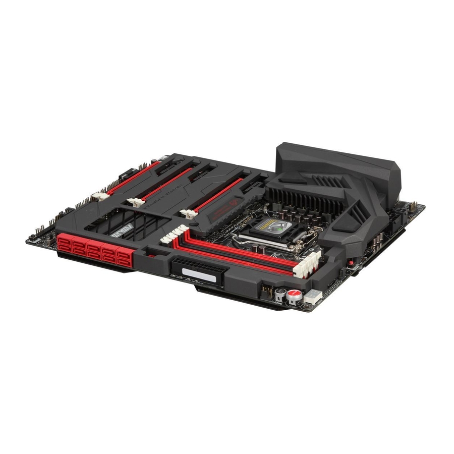
- Page 1 MAXIMUS VI FORMULA...
- Page 2 Product warranty or service will not be extended if: (1) the product is repaired, modified or altered, unless such repair, modification of alteration is authorized in writing by ASUS; or (2) the serial number of the product is defaced or missing.
-
Page 3: Table Of Contents
Contents Safety information ...................... vi About this guide ......................vii MAXIMUS VI FORMULA specifications summary ........... ix Package contents ..................... xiv Installation tools and components ................xv Chapter 1: Product Introduction Special features..................1-1 1.1.1 Product highlights................ 1-1 1.1.2 ROG unique gaming features ............. 1-2 1.1.3... - Page 4 3.6.10 ROG Effects ................3-40 Monitor menu ................... 3-41 Boot menu ....................3-45 Tools menu ....................3-50 3.9.1 ASUS EZ Flash 2 Utility ............3-50 3.9.2 ROG Secure Erase ..............3-50 3.9.3 ASUS O.C. Profile ..............3-52 3.9.4 ASUS SPD Information ............. 3-53 3.9.5...
- Page 5 Creating a RAID driver disk without entering the OS ....5-8 5.2.2 Creating a RAID driver disk in Windows ........5-8 ® 5.2.3 Installing the RAID driver during Windows OS installation ..5-9 ® Appendices Notices ........................A-1 ASUS contact information ..................A-5...
-
Page 6: Safety Information
Safety information Electrical safety • To prevent electrical shock hazard, disconnect the power cable from the electrical outlet before relocating the system. • When adding or removing devices to or from the system, ensure that the power cables for the devices are unplugged before the signal cables are connected. If possible, disconnect all power cables from the existing system before you add a device. -
Page 7: About This Guide
Refer to the following sources for additional information and for product and software updates. ASUS websites The ASUS website provides updated information on ASUS hardware and software products. Refer to the ASUS contact information. Optional documentation Your product package may include optional documentation, such as warranty flyers, that may have been added by your dealer. -
Page 8: Conventions Used In This Guide
Conventions used in this guide To ensure that you perform certain tasks properly, take note of the following symbols used throughout this manual. DANGER/WARNING: Information to prevent injury to yourself when trying to complete a task. CAUTION: Information to prevent damage to the components when trying to complete a task IMPORTANT: Instructions that you MUST follow to complete a task. -
Page 9: Maximus Vi Formula Specifications Summary
Turbo Boost Technology 2.0* ® * The Intel Turbo Boost Technology 2.0 support depends on the CPU ® types. ** Refer to www.asus.com for Intel CPU support list Chipset Intel Z87 Express Chipset ® Dual channel memory architecture 4 x DIMM, max. 32GB, DDR3 3000(O.C.) / 2933(O.C.) / 2800(O.C.) / 2666(O.C.) / 2600(O.C.) / 2500 (O.C.) / 2400 (O.C.) / 2200(O.C.) - Page 10 ASMedia USB 3.0 SuperSpeed USB HUB controller ® 4 x USB 3.0 ports (4 ports at back panel [blue]) * Supports ASUS USB3.0 Boost, UASP standard on the Intel native USB ® 3.0 is only supported under Windows ®...
- Page 11 1 x Clear CMOS button 1 x ROG Connect On/Off switch 4 x USB 2.0 ports (1 port can be switched to ROG Connect) 6 x USB 3.0 ports [blue] Back I/O Ports 1 x Optical S/PDIF out 1 x HDMI port 1 x DisplayPort 1 x LAN (RJ45) port 6 x Audio jacks...
- Page 12 - ASUS EZ Flash 2 - ASUS C.P.R. (CPU Parameter Recall) ASUS Q-Design - ASUS Q-Code - ASUS Q-Shield - ASUS Q-Connector - ASUS Q-LED (CPU, DRAM, VGA, Boot Device LED) - ASUS Q-Slot - ASUS Q-DIMM (continued on the next page)
- Page 13 ROG GameFirst II ROG RAMDisk ROG CPU-Z Software ROG Mem TweakIt Kaspersky Anti-Virus ® DAEMON Tools Pro Standard ASUS WebStorage ASUS Utilities Form Factor ATX Form Factor, 12” x 9.6” (30.5cm x 24.4cm) Specifications are subject to change without notice. xiii...
-
Page 14: Package Contents
Package contents Check your motherboard package for the following items. Motherboard ROG MAXIMUS VI FORMULA Cables 4 x 2-in-1 SATA 6 Gb/s cables 1 x SLI bridge ® Accessories I/O Shield 1 x mPCIe Combo II card with dual-band Wi-Fi 802.11 a/b/g/ n/ac + Bluetooth v4.0/3.0+HS module... -
Page 15: Installation Tools And Components
Installation tools and components 1 bag of screws Philips (cross) screwdriver PC chassis Power supply unit Intel LGA 1150 CPU Intel LGA 1150 compatible CPU Fan DDR3 DIMM SATA hard disk drive SATA optical disc drive (optional) Graphics card (optional) The tools and components in the table above are not included in the motherboard package. -
Page 17: Chapter 1: Product Introduction
This motherboard features a unique PCIe 3.0 bridge chip to support multi-GPU SLI ® ™ CrossFireX graphics cards for an unrivaled gaming performance. With the Intel ® platform to optimize the PCIe allocation of multiple GPUs, it supports up to 2-WAY SLI ® ™ 3-WAY CrossFireX configuration. ASUS MAXIMUS VI FORMULA... -
Page 18: Rog Unique Gaming Features
1.1.2 ROG unique gaming features CrossChill Choose between air or water cooling - it works with both! Unlike competing hybrid thermal solutions, CrossChill requires no fans, so there’s no noise or dust build-up. For those who prefer water cooling, you can achieve up to 23 C lower MOSFET temperatures for a more stable overclocking experience! The water channel fins help maximize the surface area for heat transfer and thanks to its G1/4 threaded fittings,... -
Page 19: Rog Exclusive Features
ROG Armor 100% exclusive to ASUS, ROG Armor is more than just a stylish addition to the ultimate gaming motherboard. ROG Armor contains two parts: a plastic vanity cover that DIYers can customize and a reinforced SECC steel support behind the PCB to prevent bending. Thermal pads also drive away heat from crucial components to reduce mainboard temperature. -
Page 20: Asus Special Features
BIOS updates, and download the latest BIOS automatically. Wi-Fi GO! ASUS Wi-Fi GO! leads the way to a more enjoyable home entertainment. With ASUS Wi-Fi GO!, you can wirelessly stream media files to DLNA devices, remotely control and access your computer using your smart device and easily transfer files between your computer and smart device. -
Page 21: Rog Rich Bundled Software
Consumers can connect their PC to a home theater system. DTS Interactive is capable of performing multi-channel encoding of DTS bitstreams on personal computers, and sending encoded bitstreams out of a digital audio connection (such as S/PDIF or HDMI) designed to deliver audio to an external decoder. ASUS MAXIMUS VI FORMULA... -
Page 22: Motherboard Overview
Motherboard overview 1.2.1 Before you proceed Take note of the following precautions before you install motherboard components or change any motherboard settings. • Unplug the power cord from the wall socket before touching any component. • Before handling components, use a grounded wrist strap or touch a safely grounded object or a metal object, such as the power supply case, to avoid damaging them due to static electricity. -
Page 23: Motherboard Layout
1.2.2 Motherboard layout Refer to 1.2.8 Internal connectors and 2.3.1 Rear I/O connection for more information about rear panel connectors and internal connectors. ASUS MAXIMUS VI FORMULA... -
Page 24: Layout Contents
Layout contents Connectors/Jumpers/Buttons and switches/Slots Page 1. Thermal sensor cable connectors (2-pin OPT_TEMP1-3) 1-49 2. CPU, chassis, and optional fan connectors (4-pin CPU_FAN, 4-pin 1-44 CPU_OPT, 4-pin OPT_FAN1-3, 4-pin CHA_FAN1-3) 3. ATX power connectors (24-pin EATXPWR; 8-pin EATX12V_1; 1-45 4-pin EATX12V_2) 4. -
Page 25: Central Processing Unit (Cpu)
Contact your retailer immediately if the PnP cap is missing, or if you see any damage to the PnP cap/socket contacts/motherboard components. ASUS will shoulder the cost of repair only if the damage is shipment/ transit-related. -
Page 26: System Memory
1.2.4 System memory The motherboard comes with four Double Data Rate 3 (DDR3) Dual Inline Memory Modules (DIMM) slots. A DDR3 module is notched differently from a DDR or DDR2 module. DO NOT install a DDR or DDR2 memory module to the DDR3 slot. Recommended memory configurations Chapter 1: Product introduction 1-10... -
Page 27: Memory Configurations
3.4 Extreme Tweaker menu for manual memory frequency adjustment. • For system stability, use a more efficient memory cooling system to support a full memory load (4 DIMMs) or overclocking condition. ASUS MAXIMUS VI FORMULA 1-11... - Page 28 MAXIMUS VI FORMULA Motherboard Qualified Vendors Lists (QVL) DDR3 3000 MHz capability Vendors Part No. Size Chip Chip Timing Voltage DIMM socket Brand support (Optional) G.SKILL F3-3000C12Q-16GTXDG 16GB (4x4GB) 12-14-14-35 1.65 • • CORSAIR CML8GX3M2A3000C12R 8GB (2x4B) 12-14-14-36 1.65 •...
- Page 29 Part No. Size Chip Chip Timing Voltage DIMM socket Brand support (Optional) G.SKILL F3-17600CL7D-4GBFLS(XMP) 4G ( 2x2G) 7-10-10-28 1.65 • GEIL GET34GB2200C9DC(XMP) 4GB (2x2GB) 9-10-9-28 1.65 • • GEIL GET38GB2200C9ADC(XMP) 8GB (2x4GB) 9-11-9-28 1.65 • • ASUS MAXIMUS VI FORMULA 1-13...
- Page 30 DDR3 2133 MHz capability Vendors Part No. Size Chip Chip Timing Voltage DIMM Brand socket support (Optional) A-DATA AX3U2133XC4G10 (XMP) 10-11-11-30 1.65 • • A-DATA AX3U2133XW8G10 (XMP) 16GB (2x8GB) 10-11-11-30 1.65 • • A-DATA AX3U2133XW8G10 (XMP) 10-11-11-30 1.65 • • Apacer 78.BAGE4.AFD0C (XMP) 8GB ( 2x4GB)
- Page 31 (Ver3.23)(XMP) (4x8GB) CORSAIR CMZ32GX3M4X1866C10(Ver 32GB 10-11-10-27 • • 3.23)(XMP) (4x8GB) CORSAIR CMZ8GX3M2A1866C9 9-10-9-27 • • (Ver8.16)(XMP) (2x4GB) CORSAIR CMZ8GX3M2A1866C9(XMP) 9-10-9-27 • (2x4GB) CORSAIR CMZ8GX3M2A1866C9G 1866 9-10-9-27 • • (Ver5.12)(XMP) (2x4GB) (continued on the next page) ASUS MAXIMUS VI FORMULA 1-15...
- Page 32 DDR3 1866 MHz capability Vendors Part No. Size Chip Chip Timing Voltage DIMM Brand socket support (Optional) Crucial BLE4G3D1869DE1XT0.16F 9-9-9-27 • • MD(XMP) G.SKILL F3-14900CL10Q2- 64GB 10-11-10-30 • • 64GBZLD(XMP) (8x8GB) G.SKILL F3-14900CL9D-8GBSR(XMP) 9-10-9-28 • • (2x4GB) G.SKILL F3-14900CL9Q-16GBXL(XMP) 16GB 9-10-9-28 •...
- Page 33 • Asint SLZ302G08-EGN1C ASint 302G08-GN1C • • Asint SLZ3128M8-EGJ1D Asint 3128M8-GJ1D • • (XMP) CORSAIR CMD16GX3M2A1600C9 16GB 9-9-9-24 • (Ver8.21)(XMP) (2x8GB) CORSAIR CMD8GX3M2A1600C8 1600 8-8- • • (Ver5.12)(XMP) (2x4GB) 8-24 (continued on the next page) ASUS MAXIMUS VI FORMULA 1-17...
- Page 34 DDR3 1600 MHz capability Vendors Part No. Size Chip Chip NO. Timing Voltage DIMM Brand socket support (Optional) CORSAIR CMD8GX3M2A1600C9 9-9-9-24 • • (Ver2.12)(XMP) (2x4GB) CORSAIR CML16GX3M4X1600C8 (Ver 16GB Heat-Sink • 2.12)(XMP) (4x4GB) Package CORSAIR CMX6GX3M3A1600C9 9-9-9-24 1.65 • (XMP) (3x2GB) CORSAIR CMX8GX3M2A1600C9...
- Page 35 KINGSTON KHX1600C9D3K8/32GX 32GB 9-9-9-27 1.65 • • (XMP) (8x4GB) KINGSTON KHX1600C9D3LK2/ 9-9-9-24 1.35 • • 8GX (XMP) (2x4GB) KINGSTON KHX1600C9D3P1K2/8G • • (2x4GB) KINGSTON KHX16C10B1K2/16X 16GB • • (XMP) (2x8GB) (continued on the next page) ASUS MAXIMUS VI FORMULA 1-19...
- Page 36 DDR3 1600 MHz capability Vendors Part No. Size Chip Chip NO. Timing Voltage DIMM Brand socket support (Optional) KINGSTON KHX16C9K2/16 16GB 1333-9-9- • • (2x8GB) 9-24 KINGSTON KHX16C9P1K2/16 16GB • • (2x8GB) KINGSTON KVR16N11/4 Hynix H5TQ2G83CFRPBC • • KINGTIGER KTG2G1600PG3(XMP) •...
- Page 37 ACTICA ACT2GHU72D8G1333M Micron D9KPT(ECC) • • ACTICA ACT2GHU72D8G1333S SAMSUNG K4B1G0846F (ECC) • • ACTICA ACT4GHU64B8H1333H Hynix H5TQ2G83AFR • • ACTICA ACT4GHU72D8H1333H Hynix H5TQ2G83AFR • • (ECC) AE32G1339U1-U 23EY4587MB3H • • (continued on the next page) ASUS MAXIMUS VI FORMULA 1-21...
- Page 38 DDR3 1333 MHz capability Vendors Part No. Size Chip Chip NO. Timing Voltage DIMM Brand socket support (Optional) AE34G1339U2-U 23EY4587MB3H • • Apacer 78.A1GC6.9L1 Apacer AM5D5808FEQSBG • • Apacer 78.B1GDE.9L10C Apacer AM5D5908CEHSBG • • Asint SLA302G08-EDJ1C ASint 302G08-DJ1C • • Asint SLA304G08-EDJ1B Asint...
- Page 39 • • Mach MXD3U133316GQ 16GB • • Xtreme (4x4GB) Mach MXD3V13332GS Mach C2S46D30-D313 • • Xtreme Xtreme MICRON MT16JTF1G64AZ- MICRON D9PCP • 1G4D1 MICRON MT8JTF25664AZ- MICRON D9PFJ • • 1G4M1 (continued on the next page) ASUS MAXIMUS VI FORMULA 1-23...
- Page 40 ASUS exclusively provides hyper DIMM support function. • Hyper DIMM support is subject to the physical characteristics of individual CPUs. Load the X.M.P. settings in the BIOS for the hyper DIMM support. • Visit the ASUS website for the latest QVL. Chapter 1: Product introduction 1-24...
-
Page 41: Expansion Slots
Slot No. Slot Description PCIe 2.0 x1_1 slot PCIe 3.0/2.0 x16/x8_1 slot PCIe 2.0 x1_2 slot PCIe 3.0/2.0 x16/x8_2 slot PCIe 2.0 x1_3 slot PCIe 3.0/2.0 x4_3 slot ASUS MAXIMUS VI FORMULA 1-25... - Page 42 PCIe operating mode VGA Configuration PCIE_x16/x8_1 PCIE_x8/x4_2 PCIE_x4_3 Single VGA/PCIe card Dual VGA/PCIe cards 3-WAY CFX • We recommend that you provide sufficient power when running CrossFireX™ or SLI ® mode. • Connect a chassis fan to the motherboard connector labeled CHA_FAN1-3 when using multiple graphics cards for better thermal environment.
-
Page 43: Onboard Buttons And Switches
The button also lights up when the system is plugged to a power source indicating that you should shut down the system and unplug the power cable before removing or installing any motherboard component. Reset button Press the reset button to reboot the system. ASUS MAXIMUS VI FORMULA 1-27... -
Page 44: Memok! Switch
BIOS has been restored to its default settings. • We recommend that you download and update to the latest BIOS version from the ASUS website at www.asus.com after using the MemOK! function. Chapter 1: Product introduction 1-28... - Page 45 Turn off your system using the power-on button to allow your system to go through POST (without entering the BIOS) when you reboot your system. Refer to section 3.8 Boot Menu for details about setting the DirectKey default • function. ASUS MAXIMUS VI FORMULA 1-29...
- Page 46 Fast Boot switch This switch allows you to enable or disable the Fast Boot feature. When enabled, the system boot speed is accelerated. Chapter 1: Product introduction 1-30...
-
Page 47: Onboard Leds
The LED does not light up when there is no hard disk drive connected to the motherboard or when the hard disk drive does not function. MemOK! LED Blinking: Indicates that MemOK! is enabled before POST. ASUS MAXIMUS VI FORMULA 1-31... - Page 48 Q LED Q LEDs check key components (CPU, DRAM, VGA card, and booting devices) in sequence during motherboard booting process. If an error is found , the corresponding LED will continue lighting until the problem is solved. This user-friendly design provides an intuitive way to locate the root problem within seconds.
- Page 49 Q-Code LEDs The Q-Code LED design provides you with a 2-digit error code that displays the system status. Refer to the Q-Code table on the next page for details. ASUS MAXIMUS VI FORMULA 1-33...
- Page 50 Q-Code table Code Description Not used Power on. Reset type detection (soft/hard). AP initialization before microcode loading System Agent initialization before microcode loading PCH initialization before microcode loading Microcode loading AP initialization after microcode loading System Agent initialization after microcode loading PCH initialization after microcode loading Cache initialization 0C –...
- Page 51 2B – 2F Memory initialization Reserved for ASL (see ASL Status Codes section below) Memory Installed 32 – 36 CPU post-memory initialization 37 – 3A Post-Memory System Agent initialization is started (continued on the next page) ASUS MAXIMUS VI FORMULA 1-35...
- Page 52 Q-Code table Code Description 3B – 3E Post-Memory PCH initialization is started DXE IPL is started Memory initialization error. Invalid memory type or incompatible memory 50 – 53 speed Unspecified memory initialization error Memory not installed Invalid CPU type or Speed CPU mismatch CPU self test failed or possible CPU cache error CPU micro-code is not found or micro-code update is failed...
- Page 53 PCI Bus Hot Plug Controller Initialization PCI Bus Enumeration PCI Bus Request Resources PCI Bus Assign Resources Console Output devices connect Console input devices connect Super IO Initialization USB initialization is started USB Reset (continued on the next page) ASUS MAXIMUS VI FORMULA 1-37...
- Page 54 Q-Code table Code Description USB Detect USB Enable 9E – 9F Reserved for future AMI codes IDE initialization is started IDE Reset IDE Detect IDE Enable SCSI initialization is started SCSI Reset SCSI Detect SCSI Enable Setup Verifying Password Start of Setup Reserved for ASL (see ASL Status Codes section below) Setup Input Wait Reserved for ASL (see ASL Status Codes section below)
- Page 55 System is waking up from the S4 sleep state 0xAC System has transitioned into ACPI mode. Interrupt controller is in PIC mode. 0xAA System has transitioned into ACPI mode. Interrupt controller is in APIC mode. ASUS MAXIMUS VI FORMULA 1-39...
-
Page 56: Internal Connectors
1.2.8 Internal connectors Intel Z87 Serial ATA 6 Gb/s connectors (7-pin SATA6G_1-6 [red]) ® These connectors connect to Serial ATA 6 Gb/s hard disk drives via Serial ATA 6 Gb/s signal cables. If you installed Serial ATA hard disk drives, you can create a RAID 0, 1, 5, and 10 configuration with the Intel Rapid Storage Technology through the onboard Intel ®... - Page 57 USB 2.0. • The USB 3.0 module is purchased separately. • These connectors are based on xHCI specification. We recommend you to install the related driver to fully use the USB 3.0 ports under Windows ® ASUS MAXIMUS VI FORMULA 1-41...
- Page 58 Digital audio connector (4-1 pin SPDIF_OUT) This connector is for an additional Sony/Philips Digital Interface (S/PDIF) port. Connect the S/PDIF Out module cable to this connector, then install the module to a slot opening at the back of the system chassis. The S/PDIF module is purchased separately.
- Page 59 Never connect a 1394 cable to the USB connectors. Doing so will damage the motherboard! You can connect the front panel USB cable to the ASUS Q-Connector (USB) first, and then install the Q-Connector (USB) to the USB connector onboard if your chassis supports front panel USB ports.
- Page 60 Ensure to fully insert the 4-pin CPU fan cable to the CPU fan connector. • The CPU_FAN connector supports the CPU fan of maximum 1A (12 W) fan power. • The CPU_FAN connector and CHA_FAN connectors support the ASUS FAN Xpert 2 feature. Chapter 1: Product introduction 1-44...
- Page 61 1000W power or above to ensure the system stability. • If you are uncertain about the minimum power supply requirement for your system, refer to the Recommended Power Supply Wattage Calculator at http://support.asus. com/PowerSupplyCalculator/PSCalculator.aspx?SLanguage=en-us for details. ASUS MAXIMUS VI FORMULA...
-
Page 62: System Panel Connector
System panel connector (20-8 pin PANEL) This connector supports several chassis-mounted functions. • System power LED (2-pin PLED) This 2-pin connector is for the system power LED. Connect the chassis power LED cable to this connector. The system power LED lights up when you turn on the system power, and blinks when the system is in sleep mode. - Page 63 Refer to the technical documentation that came with the chassis for details. mPCIe Combo II connector (36-2 pin MPCIE_COMBO_II) This connector is for the mPCIE Combo II card offers expandability solutions that also features the M.2 (NGFF) slot for M.2 SSD support. ASUS MAXIMUS VI FORMULA 1-47...
- Page 64 ROG Extension - ROG_EXT connector (18-1 pin ROG_EXT) This connector is for the OC Panel. The OC Panel allows you to perform overclocking without going to the BIOS settings, loading the OS, or using overclocking software utilities. The OC Panel is purchased separately. TPM connector (20-1 pin TPM) This connector supports a Trusted Platform Module (TPM) system, which securely store keys, digital certificates, passwords and data.
- Page 65 The optional fan 1/2/3 (OPT_FAN1/2/3) can work with the temperature sensors for a better cooling effect. The thermal sensor cables are purchased separately. ASUS MAXIMUS VI FORMULA 1-49...
-
Page 66: Probeit
1.2.9 ProbeIt The ROG ProbeIt allows you to detect your system’s current voltage and OC settings. Use a multimeter to measure the ProbeIt points even during overclocking. See the illustration below to locate the respective ProbeIt points. Using ProbeIt You may connect the multitester to the motherboard as shown on the following figure. The photos above are for reference only, the actual motherboard layout and measure points location may differ by models. -
Page 67: Crosschill
• route the water cooling kit from the CPU water block to the VRM zone • separate the VGA water cooling system and the CPU/VRM water cooling system for an optimal cooling result ASUS MAXIMUS VI FORMULA 1-51... - Page 68 Chapter 1: Product introduction 1-52...
-
Page 69: Chapter 2: Basic Installation
The diagrams in this section are for reference only. The motherboard layout may vary with models, but the installation steps are the same for all models. Install the ASUS Q-Shield to the chassis rear I/O panel. Place the motherboard into the chassis, ensuring that its rear I/O ports are aligned to the chassis’... - Page 70 Place nine screws into the holes indicated by circles to secure the motherboard to the chassis. DO NOT overtighten the screws! Doing so can damage the motherboard. Chapter 2: Basic Installation...
-
Page 71: Cpu Installation
2.1.2 CPU installation Ensure that you install the correct CPU designed for LGA1150 socket only. DO NOT install a CPU designed for LGA1155 and LGA1156 sockets on the LGA1150 socket. ASUS MAXIMUS VI FORMULA... -
Page 72: Cpu Heatsink And Fan Assembly Installation
2.1.3 CPU heatsink and fan assembly installation Apply the Thermal Interface Material to the CPU heatsink and CPU before you install the heatsink and fan if necessary. To install the CPU heatsink and fan assembly Chapter 2: Basic Installation... - Page 73 To uninstall the CPU heatsink and fan assembly ASUS MAXIMUS VI FORMULA...
-
Page 74: Dimm Installation
2.1.4 DIMM installation To remove a DIMM Chapter 2: Basic Installation... -
Page 75: Atx Power Connection
2.1.5 ATX Power connection ASUS MAXIMUS VI FORMULA... -
Page 76: Sata Device Connection
2.1.6 SATA device connection Chapter 2: Basic Installation... -
Page 77: Front I/O Connector
2.1.7 Front I/O Connector To install ASUS Q-Connector To install USB 2.0 connector To install front panel audio connector AAFP USB 2.0 To install USB 3.0 connector USB 3.0 ASUS MAXIMUS VI FORMULA... -
Page 78: Expansion Card Installation
2.1.8 Expansion Card installation To install PCIe x16 cards Chapter 2: Basic Installation 2-10... -
Page 79: Mpcie Combo Ii Installation
Align and insert the M.2 (NGFF) SSD module into the M.2 slot. The M.2 (NGFF) SSD module fits in one orientation only. If it does not fit, try reversing it. ASUS MAXIMUS VI FORMULA 2-11... - Page 80 Replace the metal cover and secure the back of the metal cover with the two short screws that you removed in Secure the front of the metal cover with the long screw that you removed in step 2. Installing the mPCIe Combo II card To install the mPCIe Combo II card to your motherboard: Remove the black screw near the 36-2 pin connector.
- Page 81 Secure the mPCIe Combo II card either to the motherboard or the rear I/O shield using the black screw that you removed in step 1. ASUS MAXIMUS VI FORMULA 2-13...
- Page 82 Installing the Wi-Fi antenna connector If you installed a Wi-Fi module on the mPCIe Combo II, you would need to install the Wi-Fi antenna connector. To install the Wi-Fi antenna connector: Remove the bolt from the Wi-Fi antenna connector but leave the washer on the washer connector.
-
Page 83: Bios Update Utility
• Updating BIOS may have risks. If the BIOS program is damaged during the process and results to the system’s failure to boot up, please contact your local ASUS Service Center. ASUS MAXIMUS VI FORMULA... -
Page 84: Motherboard Rear And Audio Connections
Motherboard rear and audio connections 2.3.1 Rear I/O connection Rear panel connectors 1. Clear CMOS 2. ASMedia USB 3.0 port E1-4 3. Optical S/PDIF OUT port 4. LAN (RJ-45) port* 5. ROG Connect button 6. Intel USB 2.0 port 7-10. The ROG Connect port is the port on bottom. It supports USB BIOS Flashback and USB Charger+ 7. -
Page 85: Audio I/O Connections
Mic In Mic In Mic In Orange – – Center/Subwoofer Center/Subwoofer Black – Rear Speaker Out Rear Speaker Out Rear Speaker Out Gray – – – Side Speaker Out 2.3.2 Audio I/O connections Audio I/O ports ASUS MAXIMUS VI FORMULA 2-17... - Page 86 Connect to Headphone and Mic Connect to Stereo Speakers Connect to 2.1 channel Speakers Chapter 2: Basic Installation 2-18...
- Page 87 Connect to 4.1 channel Speakers Connect to 5.1 channel Speakers ASUS MAXIMUS VI FORMULA 2-19...
- Page 88 Connect to 7.1 channel Speakers Chapter 2: Basic Installation 2-20...
-
Page 89: Starting Up For The First Time
While the system is ON, press the power button for less than four seconds to put the system on sleep mode or soft-off mode, depending on the BIOS setting. Press the power switch for more than four seconds to let the system enter the soft-off mode regardless of the BIOS setting. ASUS MAXIMUS VI FORMULA 2-21... - Page 90 Chapter 2: Basic Installation 2-22...
-
Page 91: Chapter 3: Bios Setup
BIOS setup Knowing BIOS The new ASUS UEFI BIOS is a Unified Extensible Interface that complies with UEFI architecture, offering a user-friendly interface that goes beyond the traditional keyboard- only BIOS controls to enable a more flexible and convenient mouse input. You can easily navigate the new UEFI BIOS with the same smoothness as your operating system. -
Page 92: Bios Setup Program
BIOS setup program Use the BIOS Setup to update the BIOS or configure its parameters. The BIOS screen include navigation keys and brief onscreen help to guide you in using the BIOS Setup program. Entering BIOS at startup To enter BIOS Setup at startup: •... -
Page 93: Ez Mode
Power Saving mode • The boot device options vary depending on the devices you installed to the system. The Boot Menu (F8) button is available only when the boot device is installed to the • system. ASUS MAXIMUS VI FORMULA... -
Page 94: Advanced Mode
3.2.2 Advanced Mode The Advanced Mode provides advanced options for experienced end-users to configure the BIOS settings. The figure below shows an example of the Advanced Mode. Refer to the following sections for the detailed configurations. To access the Advanced Mode, click Exit, then select Advanced Mode or press F7 hotkey. Menu items Menu bar General help... -
Page 95: Menu Items
This button allows you to enter notes of the activities that you have done in BIOS. • The Quick Note function does not support the following keyboard functions: delete, cut, copy and paste. • You can only use the alphanumeric characters to enter your notes. ASUS MAXIMUS VI FORMULA... -
Page 96: My Favorites
Last Modified button This button shows the items that you last modified and saved in BIOS Setup. My Favorites MyFavorites is your personal space where you can easily save and access your favorite BIOS items. Adding items to My Favorites To add frequently-used BIOS items to My Favorites: Use the arrow keys to select an item that you want to add. -
Page 97: Extreme Tweaker Menu
Be cautious when changing the settings of the Extreme Tweaker menu items. Incorrect field values can cause the system to malfunction The configuration options for this section vary depending on the CPU and DIMM model you installed on the motherboard. Scroll down to display other BIOS items. ASUS MAXIMUS VI FORMULA... - Page 98 The [X.M.P.] configuration option appears only when you install memory modules supporting the eXtreme Memory Profile(X.M.P.) Technology. ASUS MultiCore Enhancement [Enabled] Default is set to [Enabled] for maximum performance under XMP/Manual/ [Enabled] User-defined memory frequency mode.
- Page 99 The CPU bus speed to DRAM speed ratio is set to 100:100. [100:133] The CPU bus speed to DRAM speed ratio is set to 100:133. Memory Frequency [Auto] Allows you to set the memory operating frequency. The configuration options vary with the BCLK/PCIE Frequency item settings. ASUS MAXIMUS VI FORMULA...
-
Page 100: Dram Timing Control
Xtreme Tweaking [Disabled] This item may help improve some benchmarks performance. Configuration options: [Enabled] [Disabled] CPU Level Up [Auto] Allows you to select a CPU level, and the related parameters will be automatically adjusted according to the selected CPU level. Configuration options: [Auto] [4.600G] [4.400G] [4.200G] EPU Power Saving Mode [Disabled] Allows you to enable or disable the EPU power saving function. - Page 101 Load timing profile for Load 4x8GB Samsung 1.65V 2400 chipset Load 2x8GB Hynix 1.85V 2600 Load timing profile for 2x8GB Hynix 1.85V 2600 chipset Load 4x8GB Hynix 1.65V 2600 Load timing profile for 4x8GB Hynix 1.65V 2600 chipset ASUS MAXIMUS VI FORMULA 3-11...
- Page 102 Load 2x8GB New Hynix 1.80V 2933 Load 4x8GB New Hynix 1.80V 2933 chipset Load 2GB RAW MHz Load timing profile for 2GB RAW MHz chipset Load 4GB/8GB RAW MHz Load timing profile for 4GB/8GB RAW MHz chipset Maximus Tweak [Auto] [Auto] Automatically selects the mode.
- Page 103 Configuration options: [Auto] [1] - [15] DRAM IO-L (CHA_R1D0 [Auto] Configuration options: [Auto] [1] - [15] DRAM IO-L (CHA_R1D1 [Auto] Configuration options: [Auto] [1] - [15] DRAM IO-L (CHB_R0D0 [Auto] Configuration options: [Auto] [1] - [15] ASUS MAXIMUS VI FORMULA 3-13...
- Page 104 DRAM IO-L (CHB_R0D1) [Auto] Configuration options: [Auto] [1] - [15] DRAM IO-L (CHB_R1D0 [Auto] Configuration options: [Auto] [1] - [15] DRAM IO-L (CHB_R1D1 [Auto] Configuration options: [Auto] [1] - [15] Third Timings tRDRD [Auto] Configuration options: [Auto] [1] – [7] tRDRD_dr [Auto] Configuration options: [Auto] [1] –...
- Page 105 [Enable Both DIMMS] [Disable DIMM0] [Disable DIMM1] [Disable Both DIMMS] Scrambler Setting [Optimized ...] Set this item to [Optimized (ASUS)] to enhance system stability. Configuration options: [Optimized (ASUS)] [Default (MRC)] DQ Sense Amplifier [Auto] Reducing usually helps overclocking and over-voltage.
- Page 106 GPU.DIMM Post Automatically detects and displays the information about the devices or memory installed on the PCIe and DIMM slots. The field shows N/A if there are no devices installed on the slots. DIGI+ Power Control CPU Load-Line Calibration [Auto] Load-line is defined by Intel VRM specification and affects CPU power voltage.
- Page 107 Allows you to set the power phase control of the CPU. [Standard] Set the phase control based on the CPU command. [Optimized] Set the ASUS optimized phase tuning profile. [Extreme] Set the full phase mode [Manual Set manually to a faster phase response to increase system...
- Page 108 Allows you to set the power phase control of the DRAM. [Auto] Allows you to set the Auto mode. [Optimized] Allows you to set the ASUS optimized phase tuning profile. [Extreme] Allows you to set the full phase mode. Tweakers’ Paradise The subitems in this menu allow you to set the CPU ratio and features.
- Page 109 Allows you to enable or disable DMI Gen 2. Auto means Enabled. Configuration options: [Auto] [Enabled] [Disabled] DMI De-emphasis Control [-6 dB] Configure De-emphasis control on DMI. Configuration options: [-6 dB] [-3.5 db] SATA Drive Strength [Auto] SATA Drive Strength. Configuration options: [Auto] [+10] - [-10] ASUS MAXIMUS VI FORMULA 3-19...
-
Page 110: Cpu Power Management
PCIE Tuning CPU PCIE Controller [Enabled] CPU PCIE Controller. Configuration options: [Disabled] [Enabled] PCIE Clock Amplitude [Auto] Adjust the magnitude of the PCIE Clocks. Higher may be better. Configuration options: [Auto] [+5] - [-4] Internal Graphics [Auto] Keep IGD enabled based on setup options. Configuration options: [Auto] [Disabled] [Enabled] CPU Power Management The subitems in this menu allow you to set the CPU ratio and features. - Page 111 Allows you to increase or decrease the output current sensed by the CPU. It finds the balance between optimal regulating while staying below the current threshold.Configuration options: [Auto] [100%] [87.5%] [75.0%] [62.5%] [50.0%] [37.5%] [25.0%] [12.5%] [0%] [-12.5%] [-25.0%] [-37.5%] [-50.0%] [-62.5%] [-75.0%] [-87.5%] [-100%] ASUS MAXIMUS VI FORMULA 3-21...
- Page 112 Power Fast Ramp Response [Auto] Allows you to increase to enhance the response of the voltage regulator during the load transient. Configuration options: [Auto] [0.00] - [1.50] CPU Internal Power Saving Control Power Saving Level 1 Threshold [Auto] Lower value provides sufficient overclocking tolerance to enlarge the overclocking potential.
- Page 113 0.8000V to 2.0000V at 0.00625V increment. PCH Core Voltage [Auto] Allows you to set the PCH voltage. Use <+> or <-> key to adjust the value. The values range from 0.7000V to 1.8000V at 0.00625V increment. ASUS MAXIMUS VI FORMULA 3-23...
- Page 114 VTTDDR Voltage [Auto] Allows you to set the VTTDDR voltage. Use <+> or <-> key to adjust the value. The values range from 0.6000V to 1.4000V at 0.00625V increment. DRAM CTRL REF Voltage [Auto] Allows you to set the fraction of DRAM voltage given as reference on the Control lines. Use <+>...
-
Page 115: Main Menu
RTC RAM via the Clear CMOS button. • The Administrator or User Password items on top of the screen show the default [Not Installed]. After you set a password, these items show [Installed]. ASUS MAXIMUS VI FORMULA 3-25... -
Page 116: Administrator Password
Administrator Password If you have set an administrator password, we recommend that you enter the administrator password for accessing the system. Otherwise, you might be able to see or change only selected fields in the BIOS setup program. To set an administrator password: Select the Administrator Password item and press <Enter>. -
Page 117: Advanced Menu
The Advanced menu items allow you to change the settings for the CPU and other system devices. Be cautious when changing the settings of the Advanced menu items. Incorrect field values can cause the system to malfunction. ASUS MAXIMUS VI FORMULA 3-27... -
Page 118: Cpu Configuration
3.6.1 CPU Configuration The items in this menu show the CPU-related information that the BIOS automatically detects. The items in this menu may vary based on the CPU installed. Intel Adaptive Thermal Monitor [Enabled] [Enabled] Enables the overheated CPU to throttle its clock speed to cool down. [Disabled] Disables the CPU thermal monitor function. - Page 119 Configuration options: [Enabled] [Disabled] CPU C States [Auto] Allows you to enable or disable the CPU C states. Configuration options: [Auto] [Enabled] [Disabled] The following items appear only when you set the CPU C States to [Enabled]. ASUS MAXIMUS VI FORMULA 3-29...
-
Page 120: Pch Configuration
Enhanced C1 state [Enabled] Allows your processor to reduce power when the system is in idle mode. Configuration options: [Enabled] [Disabled] CPU C3 Report [Enabled] Allows you to disable or enable the CPU C3 report to the operating system. Configuration options: [Enabled] [Disabled] CPU C6 Report [Enabled] Allows you to disable or enable the CPU C6 report to the operating system. - Page 121 Allows you to enable or disable Hybrid Hard Disk support. Configuration options: [Enabled] [Disabled] Intel (R) Smart Connect Technology ISCT Support [Disabled] Allow you to enable or disable the Intel Smart Connect Technology. ® Configuration options: [Enabled] [Disabled] ASUS MAXIMUS VI FORMULA 3-31...
-
Page 122: Sata Configuration
3.6.3 SATA Configuration While entering Setup, the BIOS automatically detects the presence of SATA devices. The SATA Port items show Empty if no SATA device is installed to the corresponding SATA port. Scroll down to display the other BIOS items. SATA Mode Selection [AHCI] Allows you to set the SATA configuration. -
Page 123: System Agent Configuration
Configuration options: [Disabled] [Enabled] NB PCIe Configuration Allows you to configure the NB PCI Express settings. PCIEx16_1/2/3 Link Speed [Auto] Allows you to configure the PCIEx16 speed for slots 1 and 2. Configuration options: [Auto] [Gen1] [Gen2] [Gen3] ASUS MAXIMUS VI FORMULA 3-33... -
Page 124: Memory Configuration
DMI Link ASPM Control [Auto] Allows you to enable or disable the control of Active State Power Management on SA side of the DMI Link. Configuration options: [Auto] [Disabled] [L0s] [L1] [L0sL1] PEG - ASPM [Disabled] Allows you to control ASPM support for the PEG device. Configuration options: [Disabled] [Auto] [ASPM L0s] [ASPM L1] [ASPM L0sL1] Memory Configuration Allows you to configure the memory configuration parameters. -
Page 125: Usb Configuration
Enables the support for operating systems without an EHCI hand-off feature. [Disabled] Disables the EHCI Hand-off support. USB Single Port Control Allows you to enable or disable the individual USB port. Refer to section 1.2.2 Motherboard layout for the location of the USB ports. ASUS MAXIMUS VI FORMULA 3-35... -
Page 126: Platform Misc Configuration
3.6.6 Platform Misc Configuration The items in this menu allow you to configure the platform-related features. PCI Express Native Power Management [Disabled] Allows you to enhance the power saving feature of PCI Express and perform ASPM operations in the operating system. Configuration options: [Disabled] [Enabled] The following item appears only when you set the PCI Express Native Power Management to [Enabled]. -
Page 127: Onboard Devices Configuration
Sets the front panel audio connector (AAFP) mode to high definition audio. [AC97] Sets the front panel audio connector (AAFP) mode to legacy AC’97 SPDIF Out Type [SPDIF] [SPDIF] Sets to an SPDIF audio output. [HDMI] Sets to an HDMI audio output. ASUS MAXIMUS VI FORMULA 3-37... - Page 128 Bluetooth Controller [Enabled] [Enabled] Enables the onboard Bluetooth controller. [Disabled] Disables the onboard Bluetooth controller. Wi-Fi Controller [Enabled] [Enabled] Enables the onboard Wi-Fi controller. [Disabled] Disables the onboard Wi-Fi controller. ASM1061 Storage Controller (SATA6G_E12/34) [Enabled] Allows you to select the ASM1061 storage controller operating mode. [Disabled] Disables the ASM1061 storage controller.
-
Page 129: Apm
PCIE LAN devices. Power On By RTC [Disabled] [Disabled] Disables RTC to generate a wake event. When set to [Enabled], the items RTC Alarm Date (Days) and Hour/ [Enabled] Minute/Second will become user-configurable with set values. ASUS MAXIMUS VI FORMULA 3-39... -
Page 130: Network Stack
3.6.9 Network Stack Network Stack [Disabled] This item allows you to disable or enable the UEFI network stack. Configuration options: [Disabled] [Enable] The following items appear only when you set the Network Stack to [Enabled]. Ipv4/Ipv6 PXE Support [Enabled] Allows you to enable or disable the Ipv4/Ipv6 PXE boot option. Configuration options: [Disabled] [Enabled] 3.6.10 ROG Effects... -
Page 131: Monitor Menu
(RPM). If any of the fans is not connected to the motherboard, the field shows [N/A]. These items are not user-configurable. Press <Enter> and select [Ignore] if you do not wish to display the detected temperatures. ASUS MAXIMUS VI FORMULA 3-41... -
Page 132: Fan Speed Control
Fan Speed Control CPU Q-Fan Control [Auto] [Disabled] Disables the Q-Fan control. [Auto] Enables the CPU Q-Fan control for 4-pin CPU fan. Select this mode for the PWM mode Q-Fan control. [Advance Mode] When a 3-pin CPU fan is installed, select this mode for the DC mode Q-Fan control. - Page 133 Use the <+> and <-> keys to adjust the minimum chassis fan duty cycle. The values range from 60% to 100%. When the chassis temperature is under 40ºC, the chassis fan will operate at the minimum duty cycle. ASUS MAXIMUS VI FORMULA 3-43...
- Page 134 OPTFAN 1-3 Control [Disabled] Allows you to disable or set the optional fans’ warning speeds. Configuration options: [Disabled] [Duty Mode] [Profile Mode] [User Mode] The following items appear only when you set OPTFAN 1- 3 to [Duty Model]. OPTFAN 1-3 Duty Allows you to set the optional fans’...
-
Page 135: Boot Menu
Next Boot after AC Power Loss [Normal Boot] [Normal Boot] Returns to normal boot on the next boot after an AC power loss. [Fast Boot] Accelerates the boot speed on the next boot after an AC power loss. ASUS MAXIMUS VI FORMULA 3-45... - Page 136 HW Fast Boot [Disabled] Allows the system to enable or disable the HW Fast Boot. Configuration options: [Disabled] [Enabled] DirectKey [Enabled] [Disabled] Disables the DirectKey function. The system will only power on or off when you press the DirectKey button. [Enabled] Allows the system to power on and go to the BIOS Setup directly when you press the DirectKey button.
- Page 137 [Legacy OPROM first] [UEFI driver first] [Ignore] Boot from PCIe/PCI Expansion Devices [Legacy OPROM first] Allows you to select the type of PCIe/PCI expansion devices that you want to launch. Configuration options: [Legacy OPROM first] [UEFI driver first] ASUS MAXIMUS VI FORMULA 3-47...
-
Page 138: Secure Boot
Secure Boot Allows you to configure the Windows Secure Boot settings and manage its keys to protect ® the system from unauthorized access and malwares during POST. OS Type [Windows UE..] [Windows UEFI Allows you to select your installed operating system. Execute Mode] the Microsoft Secure Boot check. - Page 139 Append dbx from File Allows you to load the additional dbx from a storage device so that more db’s images cannot be loaded. The dbx file must be formatted as a UEFI variable structure with time-based authenticated variable. ASUS MAXIMUS VI FORMULA 3-49...
-
Page 140: Tools Menu
To launch ROG SSD Secure Erase, click Tool > ROG SSD Secure Erase on the Advanced mode menu. Check the ASUS support site for a full list of SSDs tested with Secure Erase. The drive may become unstable if you run Secure Erase on an incompatible SSD. - Page 141 SSDs might be locked if the Secure Erase process is either incomplete or was stopped. This may be due to a third party software that uses a different password defined by ASUS. You have to unlock the SSD in the software before proceeding with Secure Erase.
-
Page 142: Asus O.c. Profile
3.9.3 ASUS O.C. Profile This item allows you to store or load multiple BIOS settings. The O.C. Profile Configuration items show Not Installed if no profile is created. Add your CMOS Profile Label Allows you to input the label of the setup profiles. -
Page 143: Asus Spd Information
CPU input voltage, BCLK Frequency, and CPU ratio in the UEFI BIOS. The saved values can be synchronized to a compatible OC Panel device and these values can be tweaked or configured using the OC Panel without going to the BIOS menu. ASUS MAXIMUS VI FORMULA 3-53... -
Page 144: Load Default
CPU Core Voltage [Auto] This item allows you to configure the amount of Voltage fed to the cores of the processor. You can use <+> or <-> key to raise or reduce the voltage by an increment of 0.003125V. The minimum voltage is 1.050000V and the maximum voltage is 2.200000V. -
Page 145: Exit Menu
This option allows you to enter the EZ Mode screen. Launch EFI Shell from filesystem device This option allows you to attempt to launch the EFI Shell application (shellx64.efi) from one of the available filesystem devices. ASUS MAXIMUS VI FORMULA 3-55... -
Page 146: Updating Bios
Inappropriate BIOS updating may result in the system’s failure to boot. Carefully follow the instructions of this chapter to update your BIOS if necessary. Visit the ASUS website at www.asus.com to download the latest BIOS file for this motherboard. The following utilities allow you to manage and update the motherboard BIOS setup program. -
Page 147: Asus Ez Flash 2
3.11.2 ASUS EZ Flash 2 ASUS EZ Flash 2 allows you to update the BIOS without having to use a bootable floppy disk or an OS-based utility. Before you start using this utility, download the latest BIOS from the ASUS website at www.asus.com. -
Page 148: Asus Crashfree Bios 3
The BIOS file in the motherboard support DVD may be older than the BIOS file published on the ASUS official website. If you want to use the newer BIOS file, download the file at support.asus.com and save it to a USB flash drive. -
Page 149: Asus Bios Updater
3.11.4 ASUS BIOS Updater The ASUS BIOS Updater allows you to update the BIOS in DOS environment. This utility also allows you to copy the current BIOS file that you can use as a backup when the BIOS fails or gets corrupted during the updating process. - Page 150 At the FreeDOS prompt, type bupdater /pc /g and press <Enter>. D:\>bupdater /pc /g The BIOS Updater screen appears as below. ASUSTek BIOS Updater for DOS V1.30 [2012/05/22] FLASH TYPE: MX1C 25L1065A Current ROM Update ROM BOARD: MAXIMUS VI FORMULA BOARD: UNKNOWN VER: 0204 UNKNOWN VER: DATE: 01/01/2012...
- Page 151 Select the Load Optimized Defaults item under the Exit BIOS menu. See Chaper 3 of your motherboard user manual for details. • Ensure to connect all SATA hard disk drives after updating the BIOS file if you have disconnected them. ASUS MAXIMUS VI FORMULA 3-61...
- Page 152 Chapter 3: BIOS setup 3-62...
-
Page 153: Chapter 4: Software Support
Support DVD information The contents of the support DVD are subject to change at any time without notice. Visit the ASUS website at www.asus.com for updates. 4.2.1 Running the support DVD Ensure that you have an Administrator account before running the support DVD in... -
Page 154: Obtaining The Software Manuals
Reader from the Utilities tab before opening the files. Acrobat ® To read about your motherboard’s utility guide: Click Manual tab > ASUS Motherboard Utility Guide. From the Manual folder, open the folder of the software manual that you wish to read. -
Page 155: Software Information
View the online help or readme file that came with the software application for more information. AI Suite 3 AI Suite 3 is an all-in-one interface that integrates several ASUS utilities and allows you to launch and operate these utilities simultaneously. Installing AI Suite 3 Ensure that you have an Administrator account before installing AI Suite 3 in Windows ®... - Page 156 Launching AI Suite 3 Windows 7 OS ® From the Desktop, click Start > All Programs > ASUS > AI Suite 3 > AI Suite 3. You can also launch AI Suite 3 in Windows 7 by clicking on the Notification area.
- Page 157 Some functions in the AI Suite 3 main menu in this user manual may vary depending on the motherboard model. • Refer to the software manual in the support DVD or visit the ASUS website at www.asus.com for detailed software configuration. ASUS MAXIMUS VI FORMULA...
-
Page 158: Dual Intelligent Processors 4
4.4.1 Dual Intelligent Processors 4 Dual Intelligent Processors 4 comes with these five utilities in one interface: 4-Way Optimization, TurboV Processing Unit (TPU), Energy Processing Unit (EPU), DIGI+ Power Control, and Fan Xpert 2. 4-Way Optimization The 4-Way Optimization utility allows you to automatically tweak the TPU, EPU, DIGI + Power Control and Fan Xpert 2 to their optimal settings. - Page 159 TurboV Processing Unit (TPU) ASUS TPU allows you to manually adjust the CPU frequency, CPU Cache and Core frequencies, DRAM frequency, and related voltages for an enhanced system stability and boost performance. Refer to the CPU documentation before adjusting CPU voltage settings. Setting a high voltage may damage the CPU permanently, and setting a low voltage may lead to an unstable system.
-
Page 160: Gpu Boost
Voltage Drag the slider to adjust CPU Core, CPU Cache, CPU Analog I/O, PCH Interfacing, VTTDDR, and PCHVLX voltages. Drag the slider to adjust DRAM, CPU System Agent, CPU Digital I/O, PCH, CPU Input, and PLL Termination voltages. Drag the slider to adjust PCH ICC Voltage Click to apply the adjustments... -
Page 161: Energy Processing Unit (Epu)
• Configured Max CPU Power may decrease the total power delivery to the CPU and affects the CPU performance under system heavy load. To restore your system to its default settings, reboot your computer. ASUS MAXIMUS VI FORMULA... - Page 162 • DRAM Power Phase Control Select Extreme for full phase mode to increase system performance or select Optimized for ASUS optimized phase tuning profile to increase DRAM power efficiency. • DRAM Current Capability A higher value brings a wider total power range and extends the overclocking frequency range simultaneously.
-
Page 163: Fan Xpert 2
Click to undo adjust the fan’s the changes responsiveness Click to apply the changes Click to go back Click to switch between the to the previous CPU and chassis fan screens screen ASUS MAXIMUS VI FORMULA 4-11... - Page 164 RPM Mode RPM Mode allows you to set the fan speed when the CPU temperature is below 75 Click and drag to adjust the fan’s speed Click to go back Click to switch between the to the previous CPU and chassis fan screens screen •...
-
Page 165: Wi-Fi Go
4.4.2 Wi-Fi GO! Wi-Fi GO! is an ASUS-exclusive Wi-Fi utility that allows you to wirelessly stream your media files to DLNA devices, control your computer using your smart device, transfer files to your smart device, and provides access to your files stored in your cloud storage. - Page 166 • Ensure that the ASUS AI Suite 3 utility is active when using the Wi-Fi GO! functions. Using Wi-Fi GO! & NFC Remote Wi-Fi GO! & NFC Remote allows you to remotely control your computer using your smart device.
-
Page 167: Using The Wake-On-Lan
Wi-Fi GO functions Cloud GO!: Allows you to remotely control and sync your files across multiple cloud • services such as ASUS WebStorage, GoogleDrive™, and DropBox ® Remote Desktop: Allows you to remotely control your desktop in real time using your •... -
Page 168: Using Remote Desktop
Using Cloud GO! On your computer, click Cloud GO! on the Wi-Fi GO! screen. Click Enter to access your cloud storage accounts. Log into your Asus WebStorage, Google Drive™ or Dropbox cloud account then click ® Sign In. Click to open... - Page 169 Wi-Fi previous screen GO! window Using DLNA Media Hub on the smart device On your smart device, tap DLNA Media Hub. Select and tap the receiver name. Tap Enter to remotely control your computer. ASUS MAXIMUS VI FORMULA 4-17...
- Page 170 Using File Transfer Click to set a destination path for file transfers from smart device to computer Click to go Click to go back to the Click to transfer files back to Wi-Fi previous screen GO! window Transferring files from your computer to your smart device To transfer files from your computer to your smart device, right-click the file then click Send to >...
- Page 171 The gyroscope and microphone functions are only supported on Windows ® • For the microphone function, the quality of the sound depends on the Wi-Fi environment. • For voice control commands, refer to http://windows.microsoft.com/en-US/windows- 8/using-speech-recognition for more details. ASUS MAXIMUS VI FORMULA 4-19...
- Page 172 Using Remote Keyboard & Mouse From your smart device, tap Remote Keyboard & Mouse then tap Enter. Tick to hold left click function Tap to set mouse sensitivity Input field Mouse tap area Control keys Tap to mimic right-click function Tap to mimic left-click Tap to scroll up or down...
-
Page 173: Wi-Fi Engine
From the Network Connections window, double-click to select a network adapter. From the list of available networks, click to select a network that you want to connect to. Some networks may require you to key in a password. ASUS MAXIMUS VI FORMULA 4-21... - Page 174 Using the AP Mode The AP mode allows you to set your system as an access point for other wireless-enabled devices. To use AP mode, click AP Mode on the Wi-Fi Engine menu. Key in a network name Key in your password Key in your password for...
-
Page 175: Ez Update
AI Suite 3 main menu bar. EZ Update screen Click to automatically update your motherboard’s driver, software and firmware Click to select a Click to update Click to search and boot logo the BIOS select the BIOS file ASUS MAXIMUS VI FORMULA 4-23... -
Page 176: Usb 3.0 Boost
• Refer to the software manual in the support DVD or visit the ASUS website at www.asus.com for detailed software configuration. • Use the USB 3.0 devices for high performance. The data transfer speed varies with USB devices. -
Page 177: System Information
Information on the AI Suite 3 main menu bar. Viewing the motherboard information From the System Information screen, click MB tab to view the motherboard’s information. Viewing the CPU information From the System Information screen, click CPU tab to view the processor’s information. ASUS MAXIMUS VI FORMULA 4-25... - Page 178 Viewing the SPD information From the System Information screen, click SPD tab to view the memory’s information. Chapter 4: Software support 4-26...
-
Page 179: Usb Bios Flashback
2.3.1 Rear I/O connection of your user manual for more details. To download the updated BIOS: From the USB BIOS Flashback screen, click Check for New BIOS Update. Wait for the system to check the latest BIOS version. ASUS MAXIMUS VI FORMULA 4-27... - Page 180 After the utility detects a new BIOS, click from the Save to: field, select the USB flash drive, then click Download. After the download is complete, click OK. Chapter 4: Software support 4-28...
-
Page 181: Ai Charger
To ensure normal charging function, disconnect and reconnect your USB device every time you enable or disable Ai Charger+. • The Ai Charger+ does not support USB hubs, USB extension cables, and generic USB cables. ASUS MAXIMUS VI FORMULA 4-29... -
Page 182: Usb Charger
2.3.1 Rear I/O connection of your user manual for more details. • The USB Charger+ does not support USB hubs and USB extension cables, and generic USB cables. • The USB Charger+ may not recognize some ASUS devices due to a special design. Chapter 4: Software support 4-30... -
Page 183: Audio Configurations
® Realtek HD Audio Manager for Windows 8 / Windows ® ® ® Advanced Configuration option tabs (vary with the audio devices connected) settings Set default device Control settings panel Analog and digital connector status ASUS MAXIMUS VI FORMULA 4-31... -
Page 184: Rog Connect
ROG Connect ROG Connect allows you to monitor and adjust the local PC through your remote PC. Setting up USB connection between your local and remote PC • Install ROG Connect on the remote PC from the provided Support DVD before using ROG Connect. - Page 185 String and Code. RC Remote RC Remote allows you to operate your local system through the ROG Connect cable. RC Diagram RC Diagram allows you to monitor and record your local system status. ASUS MAXIMUS VI FORMULA 4-33...
-
Page 186: Memtweakit
MemTweakIt MemTweakIt is a software that you can use to view all levels of memory timings. You can validate your MemTweakIt settings to generate a memory efficiency score that you can share and compare with other users on the ROG website. To use MemTweakIt, double-click on the desktop. - Page 187 To validate and save your configuration online: Launch MemTweakIt and click Validate. In Online Mode, key in your ASUS account ID and password, and click Submit. Your configuration will be displayed in MemTweakIt webpage. To validate and save your configuration manually: Launch MemTweakIt and click Validate.
-
Page 188: Ramdisk
RAMDisk RAMDisk is a data-storage software that reserves a part of your system’s memory and turns it into a high-speed virtual drive where you can store cache files and game apps for instant access. The following folders are not suitable for RAMDisk optimization. Moving them into the RAMDisk might negatively affectm the performance of your system. -
Page 189: Creating/Deleting A Junction Point
Click Browse to RAMDisk drive and select where to create its available storage a junction point. space. Click Add to finish Click to delete the adding the new existing junction junction point. point. ASUS MAXIMUS VI FORMULA 4-37... - Page 190 Synchronizing backup files After creating a junction point, RAMDisk automatically creates a backup folder in the file’s original location. Use RAMDisk to manually synchronize updates with these backup files. Click Synchronize to update your files Chapter 4: Software support 4-38...
-
Page 191: Sonic Radar
Game Presets Click to select optimal preset for your FPS game. Radar Selection Click items to select which type of threat to show on the Sonic Radar Display Click to show or hide the Game presets ASUS MAXIMUS VI FORMULA 4-39... - Page 192 Sonic Radar in-game * Battlefield 3. All rights reserved. Sonic Radar display Radar signals indicate where sound is coming from • The screen shot is for reference only and can vary depending on the game you are playing. • All rights of the FPS game Battlefield 3 is reserved to EA Digital Illusions CE AB and Electronic Arts.
-
Page 193: Game Presets And Radar Selection
Enhance sound coming from all potential threats. Enhance sound coming from footsteps. Enhance sound from voice call-outs. Enhance sound from gunshots. Enhance sound from ticking bomb. Full range setting. Bass range setting. Mid range setting. High range setting. ASUS MAXIMUS VI FORMULA 4-41... -
Page 194: Advanced Settings
4.8.3 Advanced Settings Click from the Sonic Radar main menu to show the Advanced Settings panel. Smoothness and opacity Allows you to adjust the texture and transparency of the Sonic Radar display. Move the respective sliders to adjust the smoothness and opacity. - Page 195 Adjust the Sonic Radar display size. <Left Ctrl> + <Left Alt> + <D> Set available Radar Selection depending on your game preset. <Left Ctrl> + <Left Alt> + <F> Enables or disables the sound enhancer. ASUS MAXIMUS VI FORMULA 4-43...
-
Page 196: Perfect Voice
Perfect Voice Sonic Radar comes with the Perfect voice, a single microphone noise reduction solution initially designed for Voice-Over-IP (VOIP) software. With Perfect voice, you can deliver perfectly enunciated voice call-outs. Perfect voice works via two major features: Noise Gate and Noise Reduction. Noise Gate Noise gate cuts the ambient noise in pauses or periods of silence in-between words or sentences. -
Page 197: Chapter 5: Raid Support
With the RAID 10 configuration you get all the benefits of both RAID 0 and RAID 1 configurations. Use four new hard disk drives or use an existing drive and three new drives for this setup. ASUS MAXIMUS VI FORMULA... -
Page 198: Installing Serial Ata Hard Disks
5.1.2 Installing Serial ATA hard disks The motherboard supports Serial ATA hard disk drives. For optimal performance, install identical drives of the same model and capacity when creating a disk array. To install the SATA hard disks for a RAID configuration: Install the SATA hard disks into the drive bays. -
Page 199: Intel ® Rapid Storage Technology Option Rom Utility
The RAID BIOS setup screens shown in this section are for reference only and may not exactly match the items on your screen. The utility supports maximum four hard disk drives for RAID configuration. ASUS MAXIMUS VI FORMULA... - Page 200 Creating a RAID set To create a RAID set: From the utility main menu, select 1. Create RAID Volume and press <Enter>. The following screen appears: Intel(R) Rapid Storage Technology - Option ROM - v10.5.1.1070 Copyright(C) 2003-10 Intel Corporation. All Rights Reserved. [ CREATE VOLUME MENU ] Name: Volume0...
- Page 201 WARNING: ALL DATA ON SELECTED DISKS WILL BE LOST. Are you sure you want to create this volume? (Y/N): Press <Y> to create the RAID volume and return to the main menu, or <N> to go back to the CREATE VOLUME menu. ASUS MAXIMUS VI FORMULA...
- Page 202 Deleting a RAID set Be cautious when deleting a RAID set. You will lose all data on the hard disk drives when you delete a RAID set. To delete a RAID set: From the utility main menu, select 2. Delete RAID Volume and press <Enter>. The following screen appears: [ DELETE VOLUME MENU ] Name...
- Page 203 Rapid Storage Technology Option ROM utility ® To exit the utility: From the utility main menu, select 5. Exit, and then press <Enter>. The following warning message appears: [ CONFIRM EXIT ] Are you sure you want to exit? (Y/N): ASUS MAXIMUS VI FORMULA...
-
Page 204: Creating A Raid Driver Disk
Creating a RAID driver disk A floppy disk with the RAID driver is required when installing a Windows operating system ® on a hard disk drive that is included in a RAID set. The motherboard does not provide a floppy drive connector. You have to use a USB floppy disk drive when creating a SATA RAID driver disk. -
Page 205: Installing The Raid Driver During Windows ® Os Installation
Follow the succeeding screen instructions to complete the installation. Before loading the RAID driver from a USB flash drive, you have to use another computer to copy the RAID driver from the support DVD to the USB flash drive. ASUS MAXIMUS VI FORMULA... - Page 206 Chapter 5: RAID support 5-10...
-
Page 207: Appendices
The use of shielded cables for connection of the monitor to the graphics card is required to assure compliance with FCC regulations. Changes or modifications to this unit not expressly approved by the party responsible for compliance could void the user’s authority to operate this equipment. ASUS MAXIMUS VI FORMULA... -
Page 208: Canadian Department Of Communications Statement
IC: Canadian Compliance Statement Complies with the Canadian ICES-003 Class B specifications. This device complies with RSS 210 of Industry Canada. This Class B device meets all the requirements of the Canadian interference-causing equipment regulations. This device complies with Industry Canada license exempt RSS standard(s). Operation is subject to the following two conditions: (1) this device may not cause interference, and (2) this device must accept any interference, including interference that may cause undesired operation of the device. -
Page 209: Rf Equipment Notices
ASUS Recycling/Takeback Services ASUS recycling and takeback programs come from our commitment to the highest standards for protecting our environment. We believe in providing solutions for you to be able to responsibly recycle our products, batteries, other components as well as the packaging materials. - Page 210 Bluetooth Industry Canada Statement This Class B device meets all requirements of the Canadian interference-causing equipment regulations. Cet appareil numérique de la Class B respecte toutes les exigences du Règlement sur le matériel brouilleur du Canada. NCC: Taiwan Wireless Statement Japan RF Equipment Statement KC (RF Equipment) Appendices...
-
Page 211: Asus Contact Information
+1-510-739-3777 +1-510-608-4555 Web site usa.asus.com Technical Support Telephone +1-812-282-2787 Support fax +1-812-284-0883 Online support support.asus.com ASUS COMPUTER GmbH (Germany and Austria) Address Harkort Str. 21-23, D-40880 Ratingen, Germany +49-2102-959911 Web site www.asus.de Online contact www.asus.de/sales Technical Support Telephone +49-1805-010923* Support Fax... - Page 212 Appendices...