Table of Contents
Advertisement
Advertisement
Table of Contents

Related Manuals for Asus MAXIMUS VI HERO


Summary of Contents for Asus MAXIMUS VI HERO
- Page 1 MAXIMUS VI HERO...
- Page 2 Product warranty or service will not be extended if: (1) the product is repaired, modified or altered, unless such repair, modification of alteration is authorized in writing by ASUS; or (2) the serial number of the product is defaced or missing.
-
Page 3: Table Of Contents
Contents Safety information ...................... vi About this guide ......................vii MAXIMUS VI HERO specifications summary ............ix Package contents ..................... xiii Installation tools and components ................. xiv Chapter 1: Product Introduction Special features..................1-1 1.1.1 Product highlights................ 1-1 1.1.2 ROG Gaming Features ............... 1-2 1.1.3... - Page 4 3.6.10 ROG Effects ................3-38 Monitor menu ................... 3-39 Boot menu ....................3-42 Tools menu ....................3-47 3.9.1 ASUS EZ Flash 2 Utility ............3-47 3.9.2 ROG Secure Erase ..............3-47 3.9.3 ASUS O.C. Profile ..............3-49 3.9.4 ASUS SPD Information ............. 3-50 3.9.5...
- Page 5 Creating a RAID driver disk without entering the OS ....5-7 5.2.2 Creating a RAID driver disk in Windows ® ..............5-8 5.2.3 Installing the RAID driver during Windows OS installation ..5-8 ® Appendices Notices ........................A-1 ASUS contact information ..................A-4...
-
Page 6: Safety Information
Safety information Electrical safety • To prevent electrical shock hazard, disconnect the power cable from the electrical outlet before relocating the system. • When adding or removing devices to or from the system, ensure that the power cables for the devices are unplugged before the signal cables are connected. If possible, disconnect all power cables from the existing system before you add a device. -
Page 7: About This Guide
Refer to the following sources for additional information and for product and software updates. ASUS website The ASUS website (www.asus.com) provides updated information on ASUS hardware and software products. Optional documentation Your product package may include optional documentation, such as warranty flyers, that may have been added by your dealer. -
Page 8: Conventions Used In This Guide
Conventions used in this guide To ensure that you perform certain tasks properly, take note of the following symbols used throughout this manual. DANGER/WARNING: Information to prevent injury to yourself when trying to complete a task. CAUTION: Information to prevent damage to the components when trying to complete a task IMPORTANT: Instructions that you MUST follow to complete a task. -
Page 9: Maximus Vi Hero Specifications Summary
Turbo Boost Technology 2.0* ® * The Intel Turbo Boost Technology 2.0 support depends on the CPU ® types. ** Refer to www.asus.com for Intel CPU support list Chipset Intel Z87 Express Chipset ® Dual channel memory architecture 4 x DIMM, max. 32GB, DDR3 2800 (O.C.) / 2666 (O.C.) / 2600 (O.C.) / 2500 (O.C.) / 2400 (O.C.) / 2200 (O.C.) / 2133 (O.C.) / 2000... - Page 10 6 x USB 3.0 ports (4 ports at back panel [blue], 2 ports at mid-board [red]*) 8 x USB 2.0 ports (4 ports at back panel, for ROG Connect; 4 ports at mid-board**) * Supports ASUS USB 3.0 Boost, UASP standard on the Intel native ® USB 3.0 is only supported under Windows ®...
- Page 11 - ASUS EZ Flash 2 - ASUS C.P.R. (CPU Parameter Recall) ASUS Q-Design - ASUS Q-Code - ASUS Q-Shield - ASUS Q-Connector - ASUS Q-LED (CPU, DRAM, VGA, Boot Device LED) - ASUS Q-Slot - ASUS Q-DIMM (continued on the next page)
- Page 12 ROG GameFirst II ROG RAMDisk ROG CPU-Z Software ROG Mem TweakIt Kaspersky Anti-Virus ® DAEMON Tools Pro Standard ASUS WebStorage ASUS Utilities Form Factor ATX Form Factor, 12” x 9.6” (30.5cm x 24.4cm) Specifications are subject to change without notice.
-
Page 13: Package Contents
Package contents Check your motherboard package for the following items. Motherboard ROG MAXIMUS VI HERO Cables 3 x 2-in-1 SATA 6 Gb/s cables 1 x SLI bridge ® Accessories I/O Shield 1 x 12-in-1 ROG cable label 1 x 2-in-1 Q-Connector kit... -
Page 14: Installation Tools And Components
Installation tools and components 1 bag of screws Philips (cross) screwdriver PC chassis Power supply unit Intel LGA 1150 CPU Intel LGA 1150 compatible CPU Fan DDR3 DIMM SATA hard disk drive SATA optical disc drive (optional) Graphics card (optional) The tools and components in the table above are not included in the motherboard package. -
Page 15: Chapter 1: Product Introduction
® ™ CrossFireX graphics cards for an unrivaled gaming performance. With the Intel ® platform to optimize the PCIe allocation of multiple GPUs, it supports up to 4-WAY GPU SLI ® ™ or CrossFireX configuration. . ASUS MAXIMUS VI HERO... -
Page 16: Rog Gaming Features
GameFirst II ASUS GameFirst II, with cFOS Traffic Shaping technology, provides a powerful and user- friendly network control to easily frag your gaming system. Featuring the EZ Mode for beginners’ setup and Advanced Mode for professionals’ tweaking, your frags comes first. -
Page 17: Rog Exclusive Features
ASUS Special Features AI Suite 3 With its user-friendly interface, ASUS AI Suite 3 consolidates all the exclusive ASUS features into one simple-to-use software package. It allows you to supervise fan speed control, voltage and sensor readings. This all-in-one software offers diverse and ease to use functions, with no need to switch back and forth between different utilities. -
Page 18: Rog Rich Bundled Software
1.1.5 ROG rich bundled software Kaspersky Anti-Virus ® Kaspersky Anti-Virus Personal offers premium antivirus protection for individual users and ® home offices. It is based on advanced antivirus technologies. The product incorporates the Kaspersky Anti-Virus engine, which is renowned for malicious program detection rates that ®... -
Page 19: Motherboard Overview
Before you install or remove any component, ensure that the ATX power supply is switched off or the power cord is detached from the power supply. Failure to do so may cause severe damage to the motherboard, peripherals, or components. ASUS MAXIMUS VI HERO... -
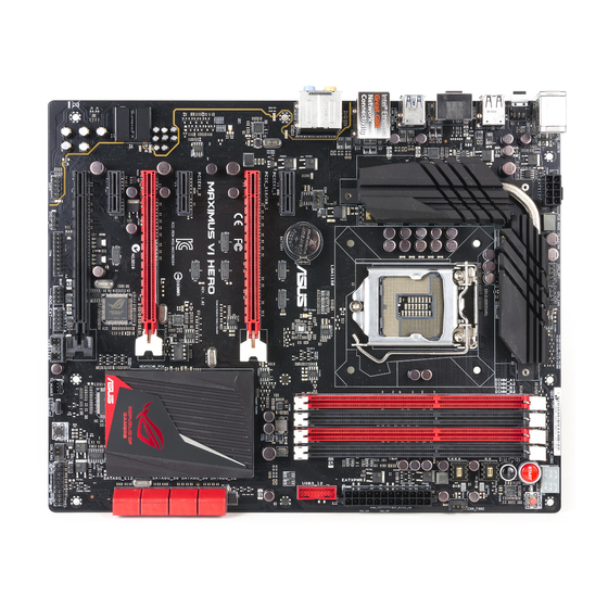
Page 20: Motherboard Layout
1.2.2 Motherboard layout Refer to 1.2.9 Internal connectors and 2.3.1 Rear I/O connection for more information about rear panel connectors and internal connectors. Chapter 1: Product introduction... -
Page 21: Layout Contents
16. USB 2.0 connectors (10-1 pin USB1112; USB1314) 1-41 17. ROG Extension connector (18-1 pin ROG_EXT) 1-46 18. TPM connector (20-1 pin TPM) 1-46 19. Digital audio connector (4-1 pin SPDIF_OUT) 1-40 20. Front panel audio connector (10-1 pin AAFP) 1-40 ASUS MAXIMUS VI HERO... -
Page 22: Central Processing Unit (Cpu)
Contact your retailer immediately if the PnP cap is missing, or if you see any damage to the PnP cap/socket contacts/motherboard components. ASUS will shoulder the cost of repair only if the damage is shipment/ transit-related. -
Page 23: System Memory
The motherboard comes with four Double Data Rate 3 (DDR3) Dual Inline Memory Modules (DIMM) slots. A DDR3 module is notched differently from a DDR or DDR2 module. DO NOT install a DDR or DDR2 memory module to the DDR3 slot. Recommended memory configurations ASUS MAXIMUS VI HERO... -
Page 24: Memory Configurations
Memory configurations You may install 1GB, 2GB, 4GB and 8GB unbuffered and non-ECC DDR3 DIMMs into the DIMM sockets. • Memory module with memory frequency higher than 2133 MHz and its corresponding timing or the loaded XMP profile is not the JEDEC memory standard. The stability and compatibility of these memory modules depend on the CPU’s capabilities and other installed devices. - Page 25 MAXIMUS VI HERO Motherboard Qualified Vendors Lists (QVL) DDR3 2800 MHz capability Vendors Part No. Size Chip Chip Timing Voltage DIMM Brand socket support (Optional) AVEXIR AVD3U28001204G-4CI 16GB ( 4x 4GB ) 12-14-14-35 1.65V • • CORSAIR CMD16GX3M4A2800C11 16GB ( 4x 4GB ) 11-14-14-35 1.65V...
- Page 26 DDR3 2500 MHz capability Vendors Part No. Size Chip Chip Timing Voltage DIMM Brand socket support (Optional) G.SKILL F3-20000CL10Q-16GBZHD(XMP) 16GB ( 4x 4GB ) 10-11-11-31 1.65 • • DDR3 2400 MHz capability Vendors Part No. Size SS/DS Chip Chip Timing Voltage DIMM Brand...
- Page 27 PXD38G2133C11K(XMP) 8GB ( 2x 4GB ) 9-9-9-24 1.65 • Patriot PXD38G2133C11K(XMP) 8GB ( 2x 4GB ) 2133 11-11- • • 11-27 Team TLD38G2133HC11ABK 11-11-11-31 1.65 • • (XMP) Team TXD34096M2133HC11A- 11-11-11-31 1.65 • • V(XMP) ASUS MAXIMUS VI HERO 1-13...
- Page 28 DDR3 2000 MHz capability Vendors Part No. Size Chip Chip NO. Timing Voltage DIMM Brand socket support (Optional) AEXEA AXA3ES2G2000LG28V 1.65 • • (XMP) AEXEA AXA3ES4GK2000LG28V 4GB ( 2x 2GB ) 1.65 • • (XMP) Apacer 78.AAGD5.9KD (XMP) 6GB ( 3x 2GB ) 9-9-9-27 •...
- Page 29 8GB ( 2x 4GB ) 9-11-9-27 1.65 • • Patriot PXD38G1866ELK(XMP) 8GB ( 2x 4GB ) 1866 9-10- • • 9-27 Team TED34G1866HC13BK • • Team TED38G1866HC-13BK • • Team TLD34G1866HC9KBK(XMP) 9-11-9-27 • • Team TLD38G1866HC10SBK(XMP) 10-11-10-30 • • ASUS MAXIMUS VI HERO 1-15...
- Page 30 DDR3 1800 MHz capability Vendors Part No. Size Chip Chip Timing Voltage DIMM Brand socket support (Optional) G.SKILL F3-14400CL9D-4GBRL(XMP) 4GB ( 2x 2GB ) 9-9-9-24 1.65 • • DDR3 1600 MHz capability Vendors Part No. Size Chip Chip NO. Timing Voltage DIMM Brand...
- Page 31 9-9-9-28 • • (XMP) G.SKILL F3-12800CL7D-8GBRH 7-8-7-24 • • (XMP) (2x4GB ) G.SKILL F3-12800CL7Q-16GBXH 16GB 7-8-7-24 • • (XMP) (4x4GB ) G.SKILL F3-12800CL8D- 8-8-8-24 1.35 • 8GBECO (XMP) (2x4GB ) (continued on the next page) ASUS MAXIMUS VI HERO 1-17...
- Page 32 DDR3 1600 MHz capability Vendors Part No. Size Chip Chip NO. Timing Voltage DIMM Brand socket support (Optional) G.SKILL F3-12800CL9D- 9-9-9-24 • • 8GBRL (XMP) (2x4GB ) G.SKILL F3-12800CL9D- 9-9-9-24 1.25 • • 8GBSR2 (XMP) (2x4GB ) G.SKILL F3-12800CL9Q- 16GB 9-9-9-24 •...
- Page 33 9-9-9-24 • • D (XMP) Transcend JM1600KLH-8G Transcend TK963EBF3 • • (626633) Transcend TS1GLK64V6H SAMSUNG K4B4G0846B • • (620945) Transcend TS1GLK64W6H SAMSUNG K4B4G0846B 11-11-11- • • 28-1 Transcend TS512MLK64W6H SAMSUNG K4B4G0846B 11-11-11- • • 28-2 ASUS MAXIMUS VI HERO 1-19...
- Page 34 DDR3 1333 MHz capability Vendors Part No. Size Chip Chip NO. Timing Voltage DIMM Brand socket support (Optional) ACTICA ACT1GHU64B8F1333S SAMSUNG K4B1G0846F • • ACTICA ACT1GHU72C8G1333S SAMSUNG K4B1G0846F(ECC) • • ACTICA ACT2GHU64B8G1333M Micron D9KPT • • ACTICA ACT2GHU72D8G1333M Micron D9KPT(ECC) •...
- Page 35 MICRON MT8JTF25664AZ-1G4M1 MICRON D9PFJ • • OCZ3G1333LV4GK 9-9-9 1.65 • (2x2GB) OCZ3G1333LV8GK 9-9-9 1.65 • (2x4GB) OCZ3G1333LV8GK 9-9-9 1.65 • (2x4GB) OCZ3RPR1333C9LV8GK 9-9-9 1.65 • (2x4GB) Patriot PG38G1333EL(XMP) • • (continued on the next page) ASUS MAXIMUS VI HERO 1-21...
- Page 36 Hyper DIMM support is subject to the physical characteristics of individual CPUs. Load the X.M.P. settings in the BIOS for the hyper DIMM support. • Visit the ASUS website for the latest QVL. Visit the ASUS website for the latest QVL. Chapter 1: Product introduction...
-
Page 37: Expansion Slots
Slot No. Slot Description PCIe 2.0 x1_1 slot PCIe 3.0/2.0 x16/x8_1 slot PCIe 2.0 x1_2 slot PCIe 3.0/2.0 x16/x8_2 slot PCIe 2.0 x1_3 slot PCIe 2.0 x4_3 slot ASUS MAXIMUS VI HERO 1-23... -
Page 38: Irq Assignments For This Motherboard
PCIe operating mode VGA Configuration PCIE_x16/x8_1 PCIE_x8_2 Single VGA/PCIe card (Recommend for single VGA) Dual VGA/PCIe card • We recommend that you provide sufficient power when running CrossFireX�� or SLI We recommend that you provide sufficient power when running CrossFireX�� or SLI ®... -
Page 39: Onboard Buttons
The button also lights up when the system is plugged to a power source indicating that you should shut down the system and unplug the power cable before removing or installing any motherboard component. Reset button Press the reset button to reboot the system. ASUS MAXIMUS VI HERO 1-25... - Page 40 BIOS has been restored to its default settings. • We recommend that you download and update to the latest BIOS version from the ASUS website at www.asus.com after using the MemOK! function. Chapter 1: Product introduction 1-26...
- Page 41 Turn off your system using the power-on button to allow your system to go through POST (without entering the BIOS) when you reboot your system. • Refer to section 3.8 Boot Menu for details about setting the DirectKey default function. ASUS MAXIMUS VI HERO 1-27...
-
Page 42: Jumper
1.2.7 Jumper Clear RTC RAM (3-pin CLRTC) This jumper allows you to clear the Real Time Clock (RTC) RAM in CMOS. You can clear the CMOS memory of date, time, and system setup parameters by erasing the CMOS RTC RAM data. -
Page 43: Onboard Leds
The LED does not light up when there is no hard disk drive connected to the motherboard or when the hard disk drive does not function. MemOK! LED Blinking: Indicates that MemOK! is enabled before POST. ASUS MAXIMUS VI HERO 1-29... - Page 44 Q LED Q LEDs check key components (CPU, DRAM, VGA card, and booting devices) in sequence during motherboard booting process. If an error is found, the corresponding LED flashes until the problem is solved. This user-friendly design provides an intuitive way to locate the root problem within seconds.
- Page 45 This LED flashes when the BIOS is updating and turns off after the BIOS update. Q-Code LEDs The Q-Code LED design provides you with a 2-digit error code that displays the system status. Refer to the Q-Code table on the next page for details. ASUS MAXIMUS VI HERO 1-31...
- Page 46 Q-Code table Code Description Not used Power on. Reset type detection (soft/hard). AP initialization before microcode loading System Agent initialization before microcode loading PCH initialization before microcode loading Microcode loading AP initialization after microcode loading System Agent initialization after microcode loading PCH initialization after microcode loading Cache initialization 0C –...
-
Page 47: Q-Code Table
2B – 2F Memory initialization Reserved for ASL (see ASL Status Codes section below) Memory Installed 32 – 36 CPU post-memory initialization 37 – 3A Post-Memory System Agent initialization is started (continued on the next page) ASUS MAXIMUS VI HERO 1-33... - Page 48 Q-Code table Code Description 3B – 3E Post-Memory PCH initialization is started DXE IPL is started Memory initialization error. Invalid memory type or incompatible memory 50 – 53 speed Unspecified memory initialization error Memory not installed Invalid CPU type or Speed CPU mismatch CPU self test failed or possible CPU cache error CPU micro-code is not found or micro-code update is failed...
- Page 49 PCI Bus Hot Plug Controller Initialization PCI Bus Enumeration PCI Bus Request Resources PCI Bus Assign Resources Console Output devices connect Console input devices connect Super IO Initialization USB initialization is started USB Reset (continued on the next page) ASUS MAXIMUS VI HERO 1-35...
- Page 50 Q-Code table Code Description USB Detect USB Enable 9E – 9F Reserved for future AMI codes IDE initialization is started IDE Reset IDE Detect IDE Enable SCSI initialization is started SCSI Reset SCSI Detect SCSI Enable Setup Verifying Password Start of Setup Reserved for ASL (see ASL Status Codes section below) Setup Input Wait Reserved for ASL (see ASL Status Codes section below)
- Page 51 System is waking up from the S4 sleep state 0xAC System has transitioned into ACPI mode. Interrupt controller is in PIC mode. 0xAA System has transitioned into ACPI mode. Interrupt controller is in APIC mode. ASUS MAXIMUS VI HERO 1-37...
-
Page 52: Internal Connectors
1.2.9 Internal connectors Intel Z87 Serial ATA 6 Gb/s connectors (7-pin SATA6G_1-6 [red]) ® These connectors connect to Serial ATA 6 Gb/s hard disk drives via Serial ATA 6 Gb/s signal cables. If you installed Serial ATA hard disk drives, you can create a RAID 0, 1, 5, and 10 configuration with the Intel Rapid Storage Technology through the onboard Intel ®... - Page 53 USB 2.0. • The USB 3.0 module is purchased separately. • These connectors are based on xHCI specification. We recommend you to install the related driver to fully use the USB 3.0 ports under Windows ® ASUS MAXIMUS VI HERO 1-39...
- Page 54 Digital audio connector (4-1 pin SPDIF_OUT) This connector is for an additional Sony/Philips Digital Interface (S/PDIF) port. Connect the S/PDIF Out module cable to this connector, then install the module to a slot opening at the back of the system chassis. The S/PDIF module is purchased separately.
- Page 55 Never connect a 1394 cable to the USB connectors. Doing so will damage the motherboard! You can connect the front panel USB cable to the ASUS Q-Connector (USB) first, and then install the Q-Connector (USB) to the USB connector onboard if your chassis supports front panel USB ports.
- Page 56 CPU, chassis, and optional fan connectors (4-pin CPU_FAN; 4-pin CPU_OPT; 4-pin CHA_FAN1-3) Connect the fan cables to the fan connectors on the motherboard, ensuring that the black wire of each cable matches the ground pin of the connector. • DO NOT forget to connect the fan cables to the fan connectors. Insufficient air flow inside the system may damage the motherboard components.
- Page 57 If you are uncertain about the minimum power supply requirement for your system, If you are uncertain about the minimum power supply requirement for your system, refer to the Recommended Power Supply Wattage Calculator at http://support.asus. com/PowerSupplyCalculator/PSCalculator.aspx?SLanguage=en-us for details. ASUS MAXIMUS VI HERO...
-
Page 58: System Panel Connector 20-8 Pin Panel
System panel connector (20-8 pin PANEL) This connector supports several chassis-mounted functions. • System power LED (2-pin PLED) This 2-pin connector is for the system power LED. Connect the chassis power LED cable to this connector. The system power LED lights up when you turn on the system power, and blinks when the system is in sleep mode. - Page 59 Connect the button cable that supports DirectKey, from the chassis to this connector on the motherboard. Ensure that your chassis comes with the extra button cable that supports the DirectKey feature. Refer to the technical documentation that came with the chassis for details. ASUS MAXIMUS VI HERO 1-45...
- Page 60 ROG Extension - ROG_EXT connector (18-1 pin ROG_EXT) This connector is for the OC Panel and the other ROG device. • The OC Panel is purchased separately. • The OC Panel allows you to perform overclocking without going to the BIOS settings, loading the OS, or using overclocking software utilities.
-
Page 61: Chapter 2: Basic Installation
The diagrams in this section are for reference only. The motherboard layout may vary with models, but the installation steps are the same for all models. Install the ASUS Q-Shield to the chassis rear I/O panel. Place the motherboard into the chassis, ensuring that its rear I/O ports are aligned to the chassis’... - Page 62 Place nine screws into the holes indicated by circles to secure the motherboard to the chassis. DO NOT overtighten the screws! Doing so can damage the motherboard. Chapter 2: Basic Installation...
-
Page 63: Cpu Installation
2.1.2 CPU installation Ensure that you install the correct CPU designed for LGA1150 socket only. DO NOT install a CPU designed for LGA1155 and LGA1156 sockets on the LGA1150 socket. ASUS MAXIMUS VI HERO... -
Page 64: Cpu Heatsink And Fan Assembly Installation
2.1.3 CPU heatsink and fan assembly installation Apply the Thermal Interface Material to the CPU heatsink and CPU before you install the heatsink and fan if necessary. To install the CPU heatsink and fan assembly Chapter 2: Basic Installation... - Page 65 To uninstall the CPU heatsink and fan assembly ASUS MAXIMUS VI HERO...
-
Page 66: Dimm Installation
2.1.4 DIMM installation To remove a DIMM Chapter 2: Basic Installation... -
Page 67: Atx Power Connection
2.1.5 ATX Power connection ASUS MAXIMUS VI HERO... -
Page 68: Sata Device Connection
2.1.6 SATA device connection Chapter 2: Basic Installation... -
Page 69: Front I/O Connector
2.1.7 Front I/O Connector To install ASUS Q-Connector To install USB 2.0 connector To install front panel audio connector AAFP USB 2.0 To install USB 3.0 connector USB 3.0 ASUS MAXIMUS VI HERO... -
Page 70: Expansion Card Installation
2.1.8 Expansion Card installation To install PCIe x16 cards Chapter 2: Basic Installation 2-10... -
Page 71: Bios Update Utility
For more BIOS update utilities in BIOS setup, refer to the section Updating BIOS in Chapter 3. Updating BIOS may have risks. If the BIOS program is damaged during the process and results to the system’s failure to boot up, please contact your local ASUS Service Center. ASUS MAXIMUS VI HERO 2-11... -
Page 72: Motherboard Rear And Audio Connections
Motherboard rear and audio connections 2.3.1 Rear I/O connection Rear panel connectors 1. PS/2 Keyboard/Mouse combo port PS/2 Keyboard/Mouse combo port 2. Intel® USB 2.0 port 9 and 10. Intel® USB 2.0 port 10 supports USB BIOS Flashback and USB Charger+ 3. -
Page 73: Audio I/O Connections
Mic In Mic In Mic In Orange – – Center/Subwoofer Center/Subwoofer Black – Rear Speaker Out Rear Speaker Out Rear Speaker Out Gray – – – Side Speaker Out 2.3.2 Audio I/O connections Audio I/O ports ASUS MAXIMUS VI HERO 2-13... - Page 74 Connect to Headphone and Mic Connect to Stereo Speakers Connect to 2.1 channel Speakers Chapter 2: Basic Installation 2-14...
- Page 75 Connect to 4.1 channel Speakers Connect to 5.1 channel Speakers ASUS MAXIMUS VI HERO 2-15...
- Page 76 Connect to 7.1 channel Speakers Chapter 2: Basic Installation 2-16...
-
Page 77: Starting Up For The First Time
While the system is ON, press the power button for less than four seconds to put the system on sleep mode or soft-off mode, depending on the BIOS setting. Press the power button for more than four seconds to let the system enter the soft-off mode regardless of the BIOS setting. ASUS MAXIMUS VI HERO 2-17... - Page 78 Chapter 2: Basic Installation 2-18...
-
Page 79: Chapter 3: Bios Setup
BIOS setup Knowing BIOS The new ASUS UEFI BIOS is a Unified Extensible Interface that complies with UEFI architecture, offering a user-friendly interface that goes beyond the traditional keyboard- only BIOS controls to enable a more flexible and convenient mouse input. You can easily navigate the new UEFI BIOS with the same smoothness as your operating system. -
Page 80: Bios Setup Program
BIOS setup program Use the BIOS Setup to update the BIOS or configure its parameters. The BIOS screen include navigation keys and brief onscreen help to guide you in using the BIOS Setup program. Entering BIOS at startup To enter BIOS Setup at startup, press <Delete> during the Power-On Self Test (POST). If you do not press <Delete>, POST continues with its routines. -
Page 81: Ez Mode
Power Saving mode • The boot device options vary depending on the devices you installed to the system. The Boot Menu (F8) button is available only when the boot device is installed to the • system. ASUS MAXIMUS VI HERO... -
Page 82: Advanced Mode
3.2.2 Advanced Mode The Advanced Mode provides advanced options for experienced end-users to configure the BIOS settings. The figure below shows an example of the Advanced Mode. Refer to the following sections for the detailed configurations. To access the Advanced Mode, click Exit, then select Advanced Mode or press F7 hotkey. Menu items Menu bar General help... -
Page 83: Menu Items
This button allows you to enter notes of the activities that you have done in BIOS. • The Quick Note function does not support the following keyboard functions: delete, cut, copy and paste. • You can only use the alphanumeric characters to enter your notes. ASUS MAXIMUS VI HERO... -
Page 84: My Favorites
Last Modified button This button shows the items that you last modified and saved in BIOS Setup. My Favorites MyFavorites is your personal space where you can easily save and access your favorite BIOS items. Adding items to My Favorites To add frequently-used BIOS items to My Favorites: Use the arrow keys to select an item that you want to add. -
Page 85: Extreme Tweaker Menu
Be cautious when changing the settings of the Extreme Tweaker menu items. Incorrect field values can cause the system to malfunction The configuration options for this section vary depending on the CPU and DIMM model you installed on the motherboard. Scroll down to display other BIOS items. ASUS MAXIMUS VI HERO... - Page 86 The [X.M.P.] configuration option appears only when you install memory modules supporting the eXtreme Memory Profile(X.M.P.) Technology. ASUS MultiCore Enhancement [Enabled] Default is set to [Enabled] for maximum performance under XMP/Manual/ [Enabled] User-defined memory frequency mode.
- Page 87 The CPU bus speed to DRAM speed ratio is set to 100:100. [100:133] The CPU bus speed to DRAM speed ratio is set to 100:133. Memory Frequency [Auto] Allows you to set the memory operating frequency. The configuration options vary with the BCLK/CPU Strap Frequency item settings. ASUS MAXIMUS VI HERO...
- Page 88 Xtreme Tweaking [Disabled] This item may help improve some benchmarks performance. Configuration options: [Enabled] [Disabled] CPU Graphics Max. Ratio [Auto] Allows you to automatically optimize the CPU Graphics Ratio or manually set a value for an optimal CPU Graphics Ratio. Use the <+> or <-> keys to adjust the CPU graphics ratio. The minimum value depends on the installed CPU.
- Page 89 Configuration options: [Auto] [1] - [63] DRAM RTL (CHB_R0D0) [Auto] Configuration options: [Auto] [1] - [63] DRAM RTL (CHB_R0D1) [Auto] Configuration options: [Auto] [1] - [63] DRAM RTL (CHB_R1D0) [Auto] Configuration options: [Auto] [1] - [63] ASUS MAXIMUS VI HERO 3-11...
- Page 90 DRAM RTL (CHB_R1D1) [Auto] Configuration options: [Auto] [1] - [63] DRAM IO-L (CHA_R0D0) [Auto] Configuration options: [Auto] [1] - [15] DRAM IO-L (CHA_R0D1) [Auto] Configuration options: [Auto] [1] - [15] DRAM IO-L (CHA_R1D0) [Auto] Configuration options: [Auto] [1] - [15] DRAM IO-L (CHA_R1D1) [Auto] Configuration options: [Auto] [1] - [15] DRAM IO-L (CHB_R0D0) [Auto]...
- Page 91 [Enable Both DIMMS] [Disable DIMM0] [Disable DIMM1] [Disable Both DIMMS] Scrambler Setting [Optimized ...] Set this item to [Optimized (ASUS)] to enhance system stability. Configuration options: [Optimized (ASUS)] [Default (MRC)] DQ Sense Amplifier [Auto] Reducing usually helps overclocking and over-voltage.
- Page 92 DIGI+ Power Control CPU Load-Line Calibration [Auto] Load-line is defined by Intel VRM specification and affects CPU power voltage. The ® CPU working voltage will decrease proportionally to CPU loading. Higher load-line calibration could get higher voltage and good overclocking performance but increases the CPU and VRM thermal conditions.
- Page 93 Allows you to set the power phase control of the CPU. [Standard] Set the phase control based on the CPU command. [Optimized] Set the ASUS optimized phase tuning profile. [Extreme] Set the full phase mode [Manual Set manually to a faster phase response to increase system...
- Page 94 Allows you to set the power phase control of the DRAM. [Auto] Allows you to set the Auto mode. [Optimized] Allows you to set the ASUS optimized phase tuning profile. [Extreme] Allows you to set the full phase mode. Chapter 3: BIOS setup...
- Page 95 DMI Gen 2 [Auto] Allows you to enable or disable DMI Gen 2. Auto means Enabled. Configuration options: [Auto] [Enabled] [Disabled] DMI De-emphasis Control [-6 dB] Configure De-emphasis control on DMI. Configuration options: [-6 dB] [-3.5 db] ASUS MAXIMUS VI HERO 3-17...
-
Page 96: Cpu Power Management
PCIE Tuning Internal Graphics [Auto] Keep IGD enabled based on setup options. Configuration options: [Auto] [Disabled] [Enabled] CPU Power Management The subitems in this menu allow you to set the CPU ratio and features. Enhanced Intel SpeedStep Technology [Enabled] Allows the operating system to dynamically adjust the processor voltage and cores frequency to decrease the average power consumption and decrease average heat production. - Page 97 Allows you to increase or decrease the output current sensed by the CPU. It finds the balance between optimal regulating while staying below the current threshold. Configuration options: [Auto] [100%] [87.5%] [75.0%] [62.5%] [50.0%] [37.5%] [25.0%] [12.5%] [0%] [-12.5%] [-25.0%] [-37.5%] [-50.0%] [-62.5%] [-75.0%] [-87.5%] [-100%] ASUS MAXIMUS VI HERO 3-19...
- Page 98 Power Fast Ramp Response [Auto] Allows you to increase to enhance the response of the voltage regulator during the load transient. Configuration options: [Auto] [0.00] - [1.50] CPU Internal Power Saving Control Power Saving Level 1 Threshold [Auto] Lower value provides sufficient overclocking tolerance to enlarge the overclocking potential.
- Page 99 Regulator. Recommend disabling when overclocking. Configuration options: [Auto] [Enabled] [Disabled] Initial CPU Input Voltage [Auto] Allows you to set the CPU Input Voltage. Use <+> or <-> key to adjust the value. The values range from 0.800V to 2.440V at 0.010V increment. ASUS MAXIMUS VI HERO 3-21...
- Page 100 Eventual CPU Input Voltage [Auto] Allows you to set the Eventual CPU Input Voltage. Use <+> or <-> key to adjust the value. The values range from 0.800V to 2.440V at 0.010V increment. DRAM Voltage [Auto] Allows you to set the voltage for the system memory. Use <+> or <-> key to adjust the value. The values range from 1.20V to 2.40V at 0.005V increment.
-
Page 101: Main Menu
The Administrator or User Password items on top of the screen show the default [Not The Administrator or User Password items on top of the screen show the default [Not Installed]. After you set a password, these items show [Installed]. ASUS MAXIMUS VI HERO 3-23... -
Page 102: Administrator Password
Administrator Password If you have set an administrator password, we recommend that you enter the administrator password for accessing the system. Otherwise, you might be able to see or change only selected fields in the BIOS setup program. To set an administrator password: Select the Administrator Password item and press <Enter>. -
Page 103: Advanced Menu
The Advanced menu items allow you to change the settings for the CPU and other system devices. Be cautious when changing the settings of the Advanced menu items. Incorrect field values can cause the system to malfunction. ASUS MAXIMUS VI HERO 3-25... -
Page 104: Cpu Configuration
3.6.1 CPU Configuration The items in this menu show the CPU-related information that the BIOS automatically detects. The items in this menu may vary based on the CPU installed. Intel Adaptive Thermal Monitor [Enabled] [Enabled] Enables the overheated CPU to throttle its clock speed to cool down. [Disabled] Disables the CPU thermal monitor function. - Page 105 Configuration options: [Enabled] [Disabled] CPU C States [Auto] Allows you to enable or disable the CPU C states. Configuration options: [Auto] [Enabled] [Disabled] The following items appear only when you set the CPU C States to [Enabled]. ASUS MAXIMUS VI HERO 3-27...
-
Page 106: Pch Configuration
Enhanced C1 state [Enabled] Allows your processor to reduce power when the system is in idle mode. Configuration options: [Enabled] [Disabled] CPU C3 Report [Enabled] Allows you to disable or enable the CPU C3 report to the operating system. Configuration options: [Enabled] [Disabled] CPU C6 Report [Enabled] Allows you to disable or enable the CPU C6 report to the operating system. - Page 107 Allows you to enable or disable Hybrid Hard Disk support. Configuration options: [Enabled] [Disabled] Intel (R) Smart Connect Technology ISCT Support [Disabled] Allow you to enable or disable the Intel Smart Connect Technology. ® Configuration options: [Enabled] [Disabled] ASUS MAXIMUS VI HERO 3-29...
-
Page 108: Sata Configuration
3.6.3 SATA Configuration While entering Setup, the BIOS automatically detects the presence of SATA devices. The SATA Port items show Empty if no SATA device is installed to the corresponding SATA port. Scroll down to display the other BIOS items. SATA Mode Selection [AHCI] Allows you to set the SATA configuration. -
Page 109: System Agent Configuration
Allows you to select a primary display from iGPU, and PCIe graphical devices. Primary Display [Auto] Allows you to select the primary display from iGPU, PCIE and PCI Graphics devices. Configuration options: [Auto] [iGPU] [PCIE] ASUS MAXIMUS VI HERO 3-31... -
Page 110: Memory Configuration
iGPU Memory [Auto] Allows you to select the amount of system memory allocated to DVMT 5.0 by the iGPU. Configuration options: [Auto] [32M] [64M] [96M] [128M] [160M] [192M] [224M] [256M] [288M] [320M] [352M] [384M] [416M] [448M] [480M] [512M] [1024M] Render Standby [Auto] Allows you to enable the Intel Graphics Render Standby support to reduce iGPU ®... -
Page 111: Usb Configuration
Enables the support for operating systems without an EHCI hand-off feature. [Disabled] Disables the EHCI Hand-off support. USB Single Port Control Allows you to enable or disable the individual USB port. Refer to section 1.2.2 Motherboard layout for the location of the USB ports. ASUS MAXIMUS VI HERO 3-33... -
Page 112: Platform Misc Configuration
3.6.6 Platform Misc Configuration The items in this menu allow you to configure the platform-related features. PCI Express Native Power Management [Disabled] Allows you to enhance the power saving feature of PCI Express and perform ASPM operations in the operating system. Configuration options: [Disabled] [Enabled] The following item appears only when you set the PCI Express Native Power Management to [Enabled]. -
Page 113: Onboard Devices Configuration
Sets the front panel audio connector (AAFP) mode to high definition audio. [AC97] Sets the front panel audio connector (AAFP) mode to legacy AC’97 SPDIF Out Type [SPDIF] [SPDIF] Sets to an SPDIF audio output. [HDMI] Sets to an HDMI audio output. ASUS MAXIMUS VI HERO 3-35... - Page 114 ASM1061 Storage Controller (SATA6G_E12) [Enabled] Allows you to select the ASM1061 storage controller operating mode. [Disabled] Disables the ASM1061 storage controller. [Enabled] Enables the ASM1061 storage controller. Hot-plug [Disabled] Allows you to set the Hot Plug support. Configuration options: [Disabled] [Enabled] PCI Express X4_3 slot (black) bandwidth [X1 mode] [X1 mode] PCIeX4_3 slots runs at X1 mode with all slots enabled.
-
Page 115: Apm
PCIE LAN devices. Power On By RTC [Disabled] [Disabled] Disables RTC to generate a wake event. When set to [Enabled], the items RTC Alarm Date (Days) and Hour/ [Enabled] Minute/Second will become user-configurable with set values. ASUS MAXIMUS VI HERO 3-37... -
Page 116: Network Stack
3.6.9 Network Stack Network Stack [Disabled] This item allows you to disable or enable the UEFI network stack. Configuration options: [Disabled] [Enable] The following items appear only when you set the Network Stack to [Enabled]. Ipv4/Ipv6 PXE Support [Enabled] Allows you to enable or disable the Ipv4/Ipv6 PXE boot option. Configuration options: [Disabled] [Enabled] 3.6.10 ROG Effects... -
Page 117: Monitor Menu
(RPM). If any of the fans is not connected to the motherboard, the field shows [N/A]. These items are not user-configurable. Press <Enter> and select [Ignore] if you do not wish to display the detected temperatures. ASUS MAXIMUS VI HERO 3-39... -
Page 118: Fan Speed Control
Fan Speed Control CPU Q-Fan Control [Auto] [Disabled] Disables the Q-Fan control. [Auto] Enables the CPU Q-Fan control for 4-pin CPU fan. Select this mode for the PWM mode Q-Fan control. [Advance Mode] When a 3-pin CPU fan is installed, select this mode for the DC mode Q-Fan control. - Page 119 Use the <+> and <-> keys to adjust the minimum chassis fan duty cycle. The values range from 60% to 100%. When the chassis temperature is under 40ºC, the chassis fan will operate at the minimum duty cycle. ASUS MAXIMUS VI HERO 3-41...
-
Page 120: Boot Menu
Boot menu The Boot menu items allow you to change the system boot options. Scroll down to display the other BIOS items. Boot Configuration Fast Boot [Enabled] [Disabled] Allows your system to go back to its normal boot speed. [Enabled] Allows your system to accelerate the boot speed. - Page 121 [On] Set the power-on state of the NumLock to [Off]. [Off] Wait For ‘F1’ If Error [Enabled] [Disabled] Disables the function. [Enabled] The system waits for the <F1> key to be pressed when error occurs. ASUS MAXIMUS VI HERO 3-43...
- Page 122 Option ROM Messages [Force BIOS] [Force BIOS] The third-party ROM messages will be forced to display during the boot sequence. [Keep Current] The third-party ROM messages will be displayed only if the third-party manufacturer had set the add-on device to do so. Interrupt 19 Capture [Disabled] When set to [Enabled], allows the option ROMs to trap Interrupt 19.
-
Page 123: Secure Boot
The PK file must be formatted as a UEFI variable structure with time-based authenticated variable. KEK Management The KEK (Key-exchange Key or Key Enrollment Key) manages the Signature database (db) and Revoked Signature database (dbx). ASUS MAXIMUS VI HERO 3-45... - Page 124 Key-exchange Key (KEK) refers to Microsoft Secure Boot Key-Enrollment Key (KEK). ® Delete the KEK Allows you to delete the KEK from your system. Configuration options: [Yes] [No] Load KEK from File Allows you to load the downloaded KEK from a USB storage device. Append KEK from File Allows you to load the additional KEK from a storage device for an additional db and dbx loaded management.
-
Page 125: Tools Menu
To launch ROG SSD Secure Erase, click Tool > ROG SSD Secure Erase on the Advanced mode menu. Check the ASUS support site for a full list of SSDs tested with Secure Erase. The drive may become unstable if you run Secure Erase on an incompatible SSD. - Page 126 SSDs might be locked if the Secure Erase process is either incomplete or was stopped. This may be due to a third party software that uses a different password defined by ASUS. You have to unlock the SSD in the software before proceeding with Secure Erase.
-
Page 127: Asus O.c. Profile
We recommend that you update the BIOS file only coming from the same memory/ CPU configuration and BIOS version. Load/Save CMOS Profile From/To USB drive This item allows you to load or save CMOS profiles from or to the USB drive when clicked or selected. ASUS MAXIMUS VI HERO 3-49... -
Page 128: Asus Spd Information
3.9.4 ASUS SPD Information Allows you to view the DRAM SPD information. 3.9.5 ROG OC Panel H-Key Configure The ROG OC Panel H-Key Configure allows you to input and save values on the CPU core voltage, CPU input voltage, BCLK Frequency, and CPU ratio in the UEFI BIOS. The saved values can be synchronized to a compatible OC Panel device and these values can be tweaked or configured using the OC Panel without going to the BIOS menu. -
Page 129: Load Default
This item allows you to save the new values of the CPU Core Voltage, CPU Input Voltage, BCLK Frequency, and CPU Ratio. Load from profile This item allows you to load the previous values of the CPU Core Voltage, CPU Input Voltage, BCLK Frequency, and CPU Ratio. ASUS MAXIMUS VI HERO 3-51... -
Page 130: Exit Menu
This option allows you to exit the Setup program without saving your changes. When you select this option or if you press <Esc>, a confirmation window appears. Select Yes to discard changes and exit. ASUS EZ Mode This option allows you to enter the EZ Mode screen. Launch EFI Shell from filesystem device This option allows you to attempt to launch the EFI Shell application (shellx64.efi) from one of... -
Page 131: Updating Bios
Inappropriate BIOS updating may result in the system’s failure to boot. Carefully follow the instructions of this chapter to update your BIOS if necessary. Visit the ASUS website at www.asus.com to download the latest BIOS file for this motherboard. The following utilities allow you to manage and update the motherboard BIOS setup program. -
Page 132: Asus Ez Flash 2
3.11.2 ASUS EZ Flash 2 ASUS EZ Flash 2 allows you to update the BIOS without having to use a bootable floppy disk or an OS-based utility. Before you start using this utility, download the latest BIOS from the ASUS website at www.asus.com. -
Page 133: Asus Crashfree Bios 3
The BIOS file in the motherboard support DVD may be older than the BIOS file published on the ASUS official website. If you want to use the newer BIOS file, download the file at support.asus.com and save it to a USB flash drive. -
Page 134: Asus Bios Updater
3.11.4 ASUS BIOS Updater The ASUS BIOS Updater allows you to update the BIOS in DOS environment. This utility also allows you to copy the current BIOS file that you can use as a backup when the BIOS fails or gets corrupted during the updating process. - Page 135 Press <Tab> to switch between screen fields and use the <Up/Down/Home/End> keys to select the BIOS file and press <Enter>. BIOS Updater checks the selected BIOS file and prompts you to confirm BIOS update. Are you sure to update BIOS? ASUS MAXIMUS VI HERO 3-57...
- Page 136 Select Yes and press <Enter>. When BIOS update is done, press <ESC> to exit BIOS Updater. Restart your computer. DO NOT shut down or reset the system while updating the BIOS to prevent system boot failure! • For BIOS Updater version 0224 or later, the utility automatically exits to the DOS For BIOS Updater version 0224 or later, the utility automatically exits to the DOS prompt after updating BIOS.
-
Page 137: Chapter 4: Software Support
Support DVD information The contents of the support DVD are subject to change at any time without notice. Visit the ASUS website at www.asus.com for updates. 4.2.1 Running the support DVD Ensure that you have an Administrator account before running the support DVD in... -
Page 138: Obtaining The Software Manuals
Reader from the Utilities tab before opening the files. Acrobat ® To read about your motherboard’s utility guide: Click Manual tab > ASUS Motherboard Utility Guide. From the Manual folder, open the folder of the software manual that you wish to read. -
Page 139: Software Information
View the online help or readme file that came with the software application for more information. AI Suite 3 AI Suite 3 is an all-in-one interface that integrates several ASUS utilities and allows you to launch and operate these utilities simultaneously. Installing AI Suite 3 Ensure that you have an Administrator account before installing AI Suite 3 in Windows ®... - Page 140 Launching AI Suite 3 Windows 7 OS ® From the Desktop, click Start > All Programs > ASUS > AI Suite 3 > AI Suite 3. You can also launch AI Suite 3 in Windows 7 by clicking on the Notification area.
- Page 141 • Refer to the software manual in the support DVD or visit the ASUS website at Refer to the software manual in the support DVD or visit the ASUS website at www.asus.com for detailed software configuration.
-
Page 142: Dual Intelligent Processors 4 With 4-Way Optimization
4.4.1 Dual Intelligent Processors 4 with 4-Way Optimization Dual Intelligent Processors 4 with 4-Way Optimization comes with these five utilities in one interface: 4-Way Optimization, TurboV Processing Unit (TPU), Energy Processing Unit (EPU), DIGI+ Power Control, and Fan Xpert 2. 4-Way Optimization The 4-Way Optimization utility allows you to automatically tweak the TPU, EPU, DIGI + Power Control and Fan Xpert 2 to their optimal settings. - Page 143 Set the CPU Ratio Setting item in BIOS to [Auto] before using the CPU Frequency in • TPU. Refer to the BIOS chapter of your motherboard user manual for details. • The CPU Frequency bars show the status of the CPU cores, which vary with your CPU model. ASUS MAXIMUS VI HERO...
-
Page 144: Gpu Boost
Voltage Drag the slider to adjust CPU Core, CPU Cache, CPU Analog I/O, PCH Interfacing, VTTDDR, and PCHVLX voltages. Drag the slider to adjust DRAM, CPU System Agent, CPU Digital I/O, PCH, CPU Input, and PLL Termination voltages. Drag the slider to adjust PCH ICC Voltage Click to apply the adjustments... -
Page 145: Energy Processing Unit (Epu)
• Configured Max CPU Power may decrease the total power delivery to the CPU and affects the CPU performance under system heavy load. To restore your system to its default settings, reboot your computer. ASUS MAXIMUS VI HERO... - Page 146 • DRAM Power Phase Control Select Extreme for full phase mode to increase system performance or select Optimized for ASUS optimized phase tuning profile to increase DRAM power efficiency. • DRAM Current Capability A higher value brings a wider total power range and extends the overclocking frequency range simultaneously.
-
Page 147: Fan Xpert 2
Click or tap to apply the Click or tap Click or tap to switch changes to go back to between the CPU and the previous chassis fan screens screen ASUS MAXIMUS VI HERO 4-11... - Page 148 RPM Mode RPM Mode allows you to set the fan speed when the CPU temperature is below 75 Click and drag to adjust the fan’s speed Click to go back Click to switch between the to the previous CPU and chassis fan screens screen •...
-
Page 149: Ez Update
AI Suite 3 main menu bar. EZ Update screen Click to automatically update your motherboard’s driver, software and firmware Click to select a Click to update Click to search and boot logo the BIOS select the BIOS file ASUS MAXIMUS VI HERO 4-13... -
Page 150: Usb 3.0 Boost
• USB 3.0 Boost automatically detects the USB 3.0 devices that support UASP. For a list of UASP-supported USB 3.0 devices, visit the ASUS website at www.asus.com. • The data transfer speed varies with USB devices. For a higher data transfer performance, use a USB 3.0 device. -
Page 151: System Information
System Information. Viewing the motherboard information Click or tap the MB tab to view the motherboard’s information. Viewing the CPU information Click or tap the CPU tab to view the processor’s information. ASUS MAXIMUS VI HERO 4-15... - Page 152 Viewing the SPD information Click or tap the SPD tab to view the memory’s information. Chapter 4: Software support 4-16...
-
Page 153: Usb Bios Flashback
In the Download Setting field, tick Schedule (days) then select the number of days for the BIOS download schedule. Click or tap Apply to save the BIOS download schedule. Click or tap Cancel to cancel the download schedule. ASUS MAXIMUS VI HERO 4-17... - Page 154 Downloading the latest BIOS Before you start downloading, ensure that you have installed the USB storage device to your computer’s USB port that supports USB BIOS Flashback. Refer to section 2.3.1 Rear I/O connection of your user manual for more details. To download the updated BIOS: From the USB BIOS Flashback screen, click or tap Check for New BIOS...
-
Page 155: Usb Charger
2.3.1 Rear I/O connection of your user manual for more details. • USB Charger+ does not support USB hubs, USB extension cables, and generic USB cables. • USB Charger+ may not recognize some ASUS devices due to varying design. ASUS MAXIMUS VI HERO 4-19... -
Page 156: Audio Configurations
4.4.7 Audio configurations The Realtek audio CODEC provides 8-channel audio capability to deliver the ultimate audio ® experience on your computer. The software provides Jack-Sensing function, S/PDIF Out support, and interrupt capability. The CODEC also includes the Realtek proprietary UAJ ®... -
Page 157: Memtweakit
MemTweakIt settings to generate a memory efficiency score that you can share and compare with other users on the ROG website. To use MemTweakIt, double-click on the desktop. Click About tab and click REPUBLIC OF GAMERS to access ROG official website. Click OK to exit MemTweakIt. ASUS MAXIMUS VI HERO 4-21... - Page 158 To validate and save your configuration online: Launch MemTweakIt and click Validate. In Online Mode, key in your ASUS account ID and password, and click Submit. Your configuration will be displayed in MemTweakIt webpage. To validate and save your configuration manually: Launch MemTweakIt and click Validate.
-
Page 159: Ramdisk
Click to create RAMDisk drives Move the slider to the Click the drop-down right to set the size arrow to choose a allocation drive name for your RAMDIsk Click Add to finish creaing the RAMDIsk drive ASUS MAXIMUS VI HERO 4-23... -
Page 160: Creating/Deleting A Junction Point
To delete an existing RAMDisk drive: Click to delete the existing RAMDisk drive. Creating/Deleting a Junction Point A junction point creates a link that remaps the original contents into the RAMDisk, enabling access to the desired application or data to be done purely within the original file location. Select the Junction tab to create your junction point... - Page 161 Synchronizing backup files After creating a junction point, RAMDisk automatically creates a backup folder in the file’s original location. Use RAMDisk to manually synchronize updates with these backup files. Click Synchronize to update your files ASUS MAXIMUS VI HERO 4-25...
-
Page 162: Sonic Radar
Sonic Radar Sonic Radar is a head-up display (HUD) designed for First Person Shooting (FPS) games, that shows the precise direction and intensity of where a sound is coming from. In-game sound including gunshots, footprints, voice call-outs, or even a ticking bomb, is visualized as radar signals on the Sonic Radar display - this provides you the advantage to know potential threats and act accordingly. - Page 163 The screen shot is for reference only and can vary depending on the game you are playing. • All rights of the FPS game Battlefield 3 is reserved to EA Digital Illusions CE AB and Electronic Arts. ASUS MAXIMUS VI HERO 4-27...
-
Page 164: Game Presets And Radar Selection
4.7.2 Game presets and Radar Selection The optimized game presets and radar selection sound enhancers provide the most conducive settings that enhances your point of view while playing FPS games. Click to select a game preset. Click to select the threat to enhance. -
Page 165: Advanced Settings
Move the respective sliders to adjust the smoothness and opacity. Radar position Allows you to set a convenient position for the Sonic Radar display, anywhere on your in- game screen. Click to position the Sonic Radar display. ASUS MAXIMUS VI HERO 4-29... - Page 166 Shortcut keys Your gaming experience is further enhanced with a set of default shortcut keys that allows you to perform tasks faster and easier without exiting the game. Click to configure shortcut key tasks and key combinations. Move scroll bar to show more items and options.
-
Page 167: Perfect Voice
Effects. Refer to the screen below for a sample setting: Noise Gate Tick to enable/disable feature. Move the slider to adjust the desired effectivity level. Noise Reduction Tick to enable/disable feature. Move the slider to adjust the desired noise reduction level. ASUS MAXIMUS VI HERO 4-31... - Page 168 Chapter 4: Software support 4-32...
-
Page 169: Chapter 5: Raid Support
With the RAID 10 configuration you get all the benefits of both RAID 0 and RAID 1 configurations. Use four new hard disk drives or use an existing drive and three new drives for this setup. ASUS MAXIMUS VI HERO... -
Page 170: Installing Serial Ata Hard Disks
5.1.2 Installing Serial ATA hard disks The motherboard supports Serial ATA hard disk drives. For optimal performance, install identical drives of the same model and capacity when creating a disk array. To install the SATA hard disks for a RAID configuration: Install the SATA hard disks into the drive bays. -
Page 171: Intel ® Rapid Storage Technology Option Rom Utility
The RAID BIOS setup screens shown in this section are for reference only and may not exactly match the items on your screen. The utility supports maximum four hard disk drives for RAID configuration. ASUS MAXIMUS VI HERO... - Page 172 Creating a RAID set To create a RAID set: From the utility main menu, select 1. Create RAID Volume and press <Enter>. The following screen appears: Intel(R) Rapid Storage Technology - Option ROM - v10.5.1.1070 Copyright(C) 2003-10 Intel Corporation. All Rights Reserved. [ CREATE VOLUME MENU ] Name: Volume0...
- Page 173 WARNING: ALL DATA ON SELECTED DISKS WILL BE LOST. Are you sure you want to create this volume? (Y/N): Press <Y> to create the RAID volume and return to the main menu, or <N> to go back to the CREATE VOLUME menu. ASUS MAXIMUS VI HERO...
- Page 174 Deleting a RAID set Be cautious when deleting a RAID set. You will lose all data on the hard disk drives when you delete a RAID set. To delete a RAID set: From the utility main menu, select 2. Delete RAID Volume and press <Enter>. The following screen appears: [ DELETE VOLUME MENU ] Name...
-
Page 175: Creating A Raid Driver Disk
When the Make Disk menu appears, press <1> to create a RAID driver disk. Insert a formatted floppy disk into the USB floppy disk drive, then press <Enter>. Follow the succeeding screen instructions to complete the process. ASUS MAXIMUS VI HERO... -
Page 176: Creating A Raid Driver Disk In Windows
5.2.2 Creating a RAID driver disk in Windows ® To create a RAID driver disk in Windows ® Start Windows ® Plug the USB floppy disk drive and insert a floppy disk. Place the motherboard support DVD into the optical drive. Go to the Make Disk menu, and then click Intel AHCI/RAID Driver Disk to create a RAID driver disk. -
Page 177: Appendices
The use of shielded cables for connection of the monitor to the graphics card is required to assure compliance with FCC regulations. Changes or modifications to this unit not expressly approved by the party responsible for compliance could void the user’s authority to operate this equipment. ASUS MAXIMUS VI HERO... -
Page 178: Canadian Department Of Communications Statement
IC: Canadian Compliance Statement Complies with the Canadian ICES-003 Class B specifications. This device complies with RSS 210 of Industry Canada. This Class B device meets all the requirements of the Canadian interference-causing equipment regulations. This device complies with Industry Canada license exempt RSS standard(s). Operation is subject to the following two conditions: (1) this device may not cause interference, and (2) this device must accept any interference, including interference that may cause undesired operation of the device. - Page 179 ASUS Recycling/Takeback Services ASUS recycling and takeback programs come from our commitment to the highest standards for protecting our environment. We believe in providing solutions for you to be able to responsibly recycle our products, batteries, other components as well as the packaging materials.
-
Page 180: Asus Contact Information
+1-510-739-3777 +1-510-608-4555 Web site usa.asus.com Technical Support Telephone +1-812-282-2787 Support fax +1-812-284-0883 Online support support.asus.com ASUS COMPUTER GmbH (Germany and Austria) Address Harkort Str. 21-23, D-40880 Ratingen, Germany +49-2102-959911 Web site www.asus.de Online contact www.asus.de/sales Technical Support Telephone +49-1805-010923* Support Fax... - Page 181 ASUS MAXIMUS VI HERO...
- Page 182 Appendices...