Table of Contents
Advertisement
Quick Links
© 2013 Char-Broil, LLC Columbus, GA 31902
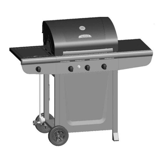
PRODUCT GUIDE
MODEL 461360513
Thermos C-343
IMPORTANT: Fill out the product record information below.
Serial Number
Date Purchased
For support and to register your
grill, please visit us at
www.charbroil.com
If you have questions or need
assistance during assembly,
please call 1-800-241-7548.
Printed in China
02
See rating label on grill for serial number.
Assembly instructions © 2013
02/15/13 • G451-001-330801
Advertisement
Table of Contents
Troubleshooting

Related Manuals for Thermos 461360513


Summary of Contents for Thermos 461360513
- Page 1 PRODUCT GUIDE MODEL 461360513 Thermos C-343 IMPORTANT: Fill out the product record information below. Serial Number See rating label on grill for serial number. Date Purchased For support and to register your grill, please visit us at www.charbroil.com If you have questions or need assistance during assembly, please call 1-800-241-7548.
-
Page 2: Table Of Contents
TABLE OF CONTENTS DANGER For Your Safety ........2-3 If you smell gas: Grilling Guide. -
Page 3: Grease Fires
WARNING CAUTION Using pots larger than 6 quarts in capacity could CALIFORNIA PROPOSITION 65 exceed weight limit of the 1. Combustible by-products produced when using side burner shelf this product contains chemicals known to the State or side shelf, of California to cause cancer, birth defects, or resulting in failure other reproductive harm. -
Page 4: Grilling Guide
Temperature - Convective Grills ONLY. GRILLING GUIDE – Getting Started The temperature gauge in the hood of your new grill measures air temperature. The air temperature inside your grill will never First Time Use be as hot as the temperature at the cooking surface. Read your Assembly Manual and ensure the grill is put together properly. - Page 5 Rotisserie Cooking GRILLING GUIDE – Grilling 101 Rotisserie cooking is best for 'round' meat, such as large roasts, whole poultry, and pork. It generally requires an accessory motor Outdoor grilling is really quite simple. You'll succeed with and spit rod that allows the meat to be turned at a constant burgers, dogs, or steaks usually on your very first try.
- Page 6 Wood Chips GRILLING GUIDE – Tips & Tricks For extra smoke flavor when grilling, try adding wood chips. Cooking on your new grill is a hands-on experience, and it is Soak the chips in water for approximately 30 minutes before recommended to remain outside with your grill while cooking.
- Page 7 GRILLING GUIDE – Cleaning Your Grill Cooking surfaces: If a bristle brush is used to clean any of the Why Clean? grill cooking surfaces, ensure no loose bristles remain on cooking We've all heard the saying 'An ounce of prevention is worth a surfaces prior to grilling.
-
Page 8: Use And Care
LP Cylinder USE AND CARE •The LP cylinder used with your grill must meet the following requirements: DANGER •Use LP cylinders only with these required measurements: 12" (30.5cm) (diameter) x 18" (45.7 cm) (tall) with 20 lb. (9 kg.) capacity maximum. •... - Page 9 LP Cylinder Exchange Connecting Regulator to the LP Cylinder •Many retailers that sell grills offer you the option of replacing 1.LP cylinder must be properly secured onto grill. (Refer to your empty LP cylinder through an exchange service. Use only assembly section.) those reputable exchange companies that inspect, precision fill, 2.Turn all control knobs to the OFF position.
- Page 10 Leak Testing Valves, Hose and Regulator 1.Turn all grill control knobs to OFF. 2.Be sure regulator is tightly connected to LP cylinder. 3.Completely open LP cylinder valve by turning hand wheel counterclockwise. If you hear a rushing sound, turn gas off immediately.
- Page 11 Safety Tips WARNING ▲ Before opening LP cylinder valve, check the coupling nut for tightness. ▲ When grill is not in use, turn off all control knobs and LP For Safe Use of Your Grill and to Avoid Serious cylinder valve. Injury: ▲...
- Page 12 Burner Flame Check • Remove cooking grates and flame tamers. Light burners, rotate WARNING knobs from HIGH to LOW. You should see a smaller flame in LOW position than seen on HIGH. Perform burner flame check Turn controls and gas source or tank OFF when not on sideburner, also.
-
Page 13: Spider Alert
3. Remove carryover tubes and burners. CAUTION Detach electrode from burner. NOTE: Removal/Detachment method will depend on the burner configuration. See different configurations in illustrations below. 5. Carefully lift each burner up and away from valve openings. SPIDER ALERT! We suggest three ways to clean the burner tubes. Use the one easiest for you. -
Page 14: Limited Warranty
LIMITED WARRANTY This warranty only applies to units purchased from an authorized retailer. Manufacturer warrants to the original consumer-purchaser only that this product shall be free from defects in workmanship and materials after correct assembly and under normal and reasonable home use for the periods indicated below beginning on the date of purchase*. -
Page 15: Parts List
PARTS LIST Qty Description Qty Description LEFT LEG ASSEMBLY BUTTON, F/ EI MODULE MATCH HOLDER CLIP, F/ GREASE CUP RIGHT LEG ASSEMBLY GREASE CUP BOTTOM SHELF TANK THUMBSCREW AXLE ROD TANK EXCLUSION WIRE, SHORT WHEEL LOGO PLATE LEG EXTENDER TANK EXCLUSION WIRE, LONG NOT Pictured FRONT PANEL …... -
Page 16: Parts Diagram
PARTS DIAGRAM... -
Page 17: Assembly
ASSEMBLY Place bottom shelf with cut out hole for LP tank next to legs with axle holes. Attach to right and left leg assemblies with 1/4-20x1-1/2" screws and 1/4-20 flange nuts. Left Leg Assembly Bottom Shelf Right Leg Assembly Axle Hole 1/4-20 1/4-20x1-1/2"... - Page 18 Insert the straight end (without hole) of the short tank exclusion wire into the hole on right front leg. Attach the other end (with ASSEMBLY hole) to right rear leg with #8x3/8" sheet metal screw, as shown (A). Insert the straight end (without hole) of the long tank exclusion wire into the hole on right front leg. Attach the other end (with hole) to bottom shelf with #8x3/8"...
- Page 19 Stand cart upright. This step requires two people to lift and position grill head onto cart. Carefully lower the grill head onto the cart. Make sure the regulator hose is hanging outside the cart. Attach with 1/4-20x1/2" machine screws. 1/4-20x1/2" Grill Head Machine Screw Qty: 4...
- Page 20 Hook side wall of shelf over support brackets on side of firebox. At back of firebox, insert 7x15 fiber washer and 1/4-20x1/2" machine screw as shown (A). Inside firebox insert 7x15 fiber washers and 1/4-20x1/2" machine screws as shown (B). Attach shelf with 1/4-20 flange nuts on each side (C).
- Page 21 Hook side wall of sideburner shelf over support brackets on side of firebox. At back of firebox, insert 7x15 fiber washer and 1/4-20x1/2" machine screw as shown (A). Inside firebox insert 7x15 fiber washers and 1/4-20x1/2" machine screws as shown (B). Attach sideburner shelf with 1/4-20 flange nuts on each side (C).
- Page 22 Position side burner valve bracket beneath side burner shelf fascia so that valve stem comes through larger center hole in fascia. Align the holes on valve bracket with left and right holes on fascia. Secure with #8-32x3/8" Stainless Steel screws (A). Place side burner into shelf.
- Page 23 Place heat tents over burners by inserting tabs into slots in front of firebox. Opposite ends of heat tents rest on pins in back of firebox. Place cooking grates onto grate rests. Unscrew ignitor cap and place AA battery into ignitor slot with positive end (+) facing outward. Replace ignitor cap onto ignitor. Cooking Grate AA Battery...
- Page 24 Hang grease cup clip from bottom of firebox and place grease cup into grease cup clip. Grease Cup Clip Grease Cup CAUTION Failure to install grease cup clip and cup will cause hot grease to drip from bottom of grill with risk of fire or property damage. LP tank is sold separately.
-
Page 25: Troubleshooting
DANGER: If a gas leak cannot be stopped, or a fire occurs due to gas leakage, call the fire department. Emergencies Possible Cause Prevention/Solution Gas leaking from • Damaged hose. • Turn off gas at LP cylinder or at source on natural gas systems. If cracked/cut/burned anything but burned, replace valve/hose/regulator. - Page 26 Troubleshooting (continued) Problem Possible Cause Prevention/Solution Burner(s) will not light ELECTRONIC IGNITION: using ignitor. • No spark, no ignition noise. • See Section I of Electronic Ignition System. (See Electronic Ignition Troubleshooting also) • No spark, some ignition noise. • See Section II of Electronic Ignition System. •...
-
Page 27: Troubleshooting
Troubleshooting - Electronic Ignition Problem (Ignition) Possible Cause Check Procedure Prevention/Solution SECTION I No sparks appear at • Battery not installed • Check battery orientation. • Install battery (make sure that “+” and “–” any electrodes when properly. connectors are oriented correctly, with “+” end up Electronic Ignition Button and “–”... - Page 28 NOTE...
- Page 29 NOTE...
- Page 30 NOTE...