Table of Contents
Advertisement
INSTALLER'S
GUIDE
Customer Property - Contains wiring, service,
and operation information. Please retain.
Model:
Used with:
BAYSENS019B
2-25 T. Packaged Heat/Cool Units
ASYSTAT666B
2-20 T. Packaged Heat Pump Units
27.5-50 T. Packaged Heat/Cool Units
20-130 T. Packaged Rooftop Units
20-80 T. Commercial Self-Contained Units
American Standard Inc, 2000
Library
Product Section
Product
Model
Literature Type
Sequence
Date
File No.
Supersedes
PROGRAMMABLE ZONE SENSOR
FOR CONSTANT VOLUME (CV) UNITS
AND HEAT PUMP (HP) UNITS
Note: The installation of this equipment must
comply with all National, State, and Local
Codes.
Since the manufacturer has a policy of continuous product
improvement, it reserves the right to change specifications and
design without notice.
SENS-IN-1D
18-HD60D29-4
Service Literature
Unitary
Unitary Accessory
T'stat, Panels, Timers, Relays
Installer's Guide
January 2001
SV-UN-ACC-SENS-IN-1D 1/01
SENS-IN-1C
1D
Advertisement
Table of Contents

Related Manuals for Trane SENS-IN-1D18-HD60D29-4


Summary of Contents for Trane SENS-IN-1D18-HD60D29-4
- Page 1 INSTALLER’S SENS-IN-1D 18-HD60D29-4 GUIDE Library Service Literature Product Section Unitary Customer Property - Contains wiring, service, Product Unitary Accessory and operation information. Please retain. Model T’stat, Panels, Timers, Relays Literature Type Installer’s Guide Sequence Date January 2001 File No. SV-UN-ACC-SENS-IN-1D 1/01 Supersedes SENS-IN-1C Model:...
-
Page 2: Literature Change History
About the Manual Literature Change History Overview of Manual SENS-IN-1A September 1997 Note: One copy of this document ships inside each Original Installation manual for mounting, wiring and pro- Programmable Zone Sensor kit and is customer gramming the Programmable Zone Sensor. property. -
Page 3: Kit Inspection
General Information Kit Inspection Remote Panel w/ NSB - BAYSENS019B This 7 day programmable sensor features 2,3 or 4 periods Upon receipt of the kit, immediately note; for Occupied or Unoccupied programming per day. If the power is interrupted, the program is retained in permanent [ ] Any visible damage to the exterior shipping package. - Page 4 General Information...
-
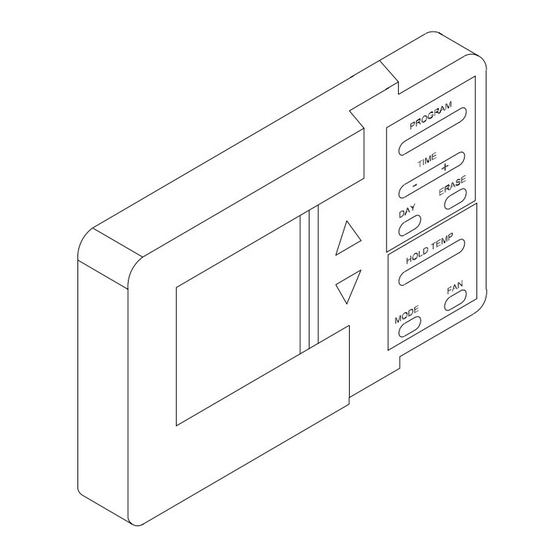
Page 5: Sensor Mounting
Installation Sensor Mounting Figure 1 Removing the Sensor from the Sub Base 1. Mounting location. - Choose a location on an interior wall near the return air grille, approximately five feet above floor level, where air circulates freely and is of average temperature for the zone. - Page 6 Installation UCM Status Inputs (4 Wires Optional) Wiring The Sub Base The ZSM can be wired to receive four (4) operating status signals from the UCM (HEAT, COOL, SYSTEM “ON”, SER- VICE). Four (4) wires from the UCM should be connected to the appropriate terminals (7, 8, 9 &...
- Page 7 Installation Figure 3 Zone Sensor Connection Diagram...
-
Page 8: Initial Power-Up
Programming And Operation Initial Power-Up To set the time, simply press the (“+”) or (“-“) side of the KEY marked TIME. Press the positive (“+”) side to advance the time in one minute intervals. Press the negative (“-“) Before applying power to the unit, verify that all wiring is side to decrease the time in one minute intervals. -
Page 9: Option Menu
Programming And Operation Option Menu Refer to the Option Menu Screen illustration and the ZSM options and option values table with a description of each option. Refer to this table while viewing or programming The Option Menu is used to set all programmable options the sensor. - Page 10 Programming And Operation Option Function Option Value Default Description Morning warm-up 0 = Disabled When enabled, Heat is turned on if the Zone 1 = Enabled temperature is 2 degrees below the heat set point temperature when the program switches from unoccupied to occupied.
-
Page 11: Programming Menu
Programming And Operation Programming Menu 9. Pressing the ERASE KEY will erase the Start Time and Desired set points. They can be left blank or re-en- tered using steps 5 through 8. Before entering the Programming Menu, select the MODE of operation using the MODE KEY. - Page 12 Programming And Operation...
- Page 13 Programming And Operation Weekly Program Record Monday Start Time Heat Set Point Cool Set Point Occupied/Unoccupied Morn Unocc Unocc Unocc Nite Unocc Tuesday Start Time Heat Set Point Cool Set Point Occupied/Unoccupied Morn Unocc Unocc Unocc Nite Unocc Wednesday Start Time Heat Set Point Cool Set Point Occupied/Unoccupied...
- Page 14 Programming And Operation Temporary Override Menu Press the FAN KEY to program the fan for ON or AUTO operation during the override period. The Temporary Override Menu is used to change tempera- Press and hold the UP and DOWN arrows simulta- ture set points, Mode of Operation, and the Zone status neously for 2 seconds to toggle the zone status be- (OCCUPIED or UNOCCUPIED) for a designated length of...
- Page 15 Programming And Operation...
- Page 16 Programming And Operation...
-
Page 17: Troubleshooting
Troubleshooting Zone Sensor Status Indicators Terminal # 10 – (SERVICE Icon) ON - Indicates by a continuously illuminated icon that the unit requires service. The Unit Control Processor (UCP) has the capability of FLASHING – Indicates that a Fan Failure has communicating four input signals (HEAT, COOL, ON, SER- occurred and service is required. - Page 18 Troubleshooting Problem Solution Check the 24 VAC power supply at terminals 11 and 14 at the Zone Sensor. Display does not come on. Verify that the terminal block is properly positioned on its pins. Check for 22 to 42 VDC between terminals 11 and 12 at the Zone Sensor. No communications to the UCP.