
Related Manuals for Lowrance GlobalMap 3300C


Summary of Contents for Lowrance GlobalMap 3300C
- Page 1 Pub. 988-0156-021 www.lowrance.com GlobalMap 3300C Mapping GPS Receiver Installation and Operation Instructions...
-
Page 2: Visit Our Web Site
Copyright © 2004 Lowrance Electronics, Inc. ® Lowrance is a registered trademark of Lowrance Electronics, Inc. MapCreate is a trademark of Lowrance Electronics, Inc. Navionics Points of Interest Data in this unit are by infoUSA, copyright 2001-2004, All Rights Reserved. infoUSA is a trademark of infoUSA, Inc. -
Page 3: Table Of Contents
Sec. 1: Read Me First! ... 1 Capabilities and Specifications: GlobalMap 3300C ... 2 How Lowrance GPS Works ... 4 Introduction to GPS and WAAS... 6 Free Training Aids Available ... 8 Unit Emulator ... 8 How to Use this Manual: Typographical Conventions... 9 Sec. - Page 4 Set Man Overboard (MOB) Waypoint... 48 Navigate Back to MOB Waypoint ... 48 Navigate to Cursor Position on Map... 49 Navigate to a Point of Interest... 50 Creating and Saving a Trail... 50 Displaying a Saved Trail ... 52 Navigating Trails... 53 Visual Trailing ...
- Page 5 Selecting a Waypoint ... 72 Set a Waypoint by Average Position ... 72 Set a Waypoint by Projecting a Position... 72 Sec. 5: System & GPS Setup Options... 73 Alarms ... 73 Check MMC Files and Storage Space ... 74 Communications Port Configuration ...
- Page 6 Track Smoothing... 97 Trail Options ... 98 Delete All Trails ... 98 Update Trail Option... 98 Update Trail Criteria (Auto, Time, Distance)... 98 Trail Update Rate (Time, Distance) ... 99 Delete Trail ... 99 New Trail... 100 Trail Visible/Invisible and Other Trail Options ... 100 Transparency ...
-
Page 7: Sec. 1: Read Me First
We'll also tell you about some of the available accessories. Section 3 covers Basic GPS Operation. It will show you how easy it is to run the GlobalMap 3300C, right out of the box. This section features a one-page GPS Quick Reference. (If you've already jumped ahead... -
Page 8: Capabilities And Specifications: Globalmap 3300C
GPS options in Section 5, System Setup and GPS Setup Options. Section 5 is organized in alphabetical order. In Section 6, we go into more detail on one of the GlobalMap 3300C's most remarkable capabilities — Searching. We'll introduce a search... - Page 9 MMC slots:...One with waterproof door (SD card compatible). Recording:... GPS uses MMC & SD cards for recording trip Back-up memory: ... Built-in memory stores GPS data for dec- Languages:... 10; menu languages selectable by user. Receiver/antenna:...External; LGC-2000 12 parallel channel Background map:...
-
Page 10: How Lowrance Gps Works
NOTICE! The storage and operation temperature range for your unit is from -4 degrees to +167 degrees Fahrenheit (-20 degrees to +75 degrees Cel- sius). Extended storage or operation in temperatures higher or lower than specified will damage the liquid crystal display in your unit. This type of damage is not covered by the warranty. - Page 11 *.lcm) can also be shared between other Lowrance GPS or so- nar/GPS units and personal computers. (For example, the exact same MMC, custom map files and GPS data files can be used interchangea- bly between your gimbal-mounted GlobalMap 3300C and the hand-held iFINDER GPS receiver.)
-
Page 12: Introduction To Gps And Waas
The unit automatically reads Custom Map Files directly from the MMC or SD card. To use a custom map, all you need to do is slide an MMC containing a map into the unit. Introduction to GPS and WAAS Well, now you know the basics of how the unit does its work. You might be ready to jump ahead to Section 2, Installation &... - Page 13 WAAS reception, but terrain, foliage or even large man-made structures can sometimes block the WAAS signal from ground receivers. You'll find that using your GPS receiver is both easy and amazingly accurate. It’s easily the most accurate method of electronic navigation available to the general public today.
-
Page 14: Free Training Aids Available
Also remember that this unit will always show navigation information in the shortest line from your present position to a waypoint, regardless of terrain! It only calculates position, it can’t know what’s between you and your destination, for example. It’s up to you to safely navigate around obstacles, no matter how you’re using this product. -
Page 15: How To Use This Manual: Typographical Conventions
The emulator works exactly like your real GPS unit. Using the GPS Simulator feature, it allows you to run GPS routes and trails, even cre- ate real waypoints you can use in the field! And that's just some of the material available on our web site. To find out all we have available, go to and look around. - Page 16 2. Press ↓ to Trail 1| 3. You are asked to wait while it converts the trail into a route. 4. The wait message disappears and the unit begins showing navigation information along the trail. Now, begin moving and follow your unit's directions. Translated into complete English, step 1 above would mean: "Start on the Map Page.
-
Page 17: Sec. 2: Installation & Accessories
Installation & Accessories Preparations You can install the GPS system in some other order if you prefer, but we recommend this installation sequence: Caution: You should read over this entire installation section before drill- ing any holes in your vehicle or vessel! 1. -
Page 18: Gps Module Installation
LGC-2000 Module, bottom view (left) and top view (right). GPS Module Installation The GPS module can be mounted on any flat surface, provided there is access behind the mounting surface for the screws. The optional mag- net allows the module to be easily used on cars or off-road vehicles. The pole mount adapter lets you mount the antenna on a pole or swivel mount that uses standard marine 1"... - Page 19 If you need to route the cable through the mounting surface, drill a 1" (25mm) hole for the cable's connector. There is a notch in the antenna housing that allows the cable to pass through to the outside, if desired, instead of routing it through the mounting surface.
-
Page 20: Connecting Directly To The Unit
GPS module mounting template. After the module is installed, connect it to the unit. The LGC-2000 can communicate with your GPS unit either directly (using the supplied ex- tension cable) or through a NMEA 2000 network. Connecting Directly to the Unit After the module is installed, attach it to the end of the Y-adapter ex- tension cable as shown in the following diagram. -
Page 21: Connecting To A Nmea 2000 Network
NOTE: The extension cable’s shorter branch will have a 60-ohm terminator at- tached to it. Do not remove this terminator. When you're not con- necting to a NMEA 2000 buss, you must leave the terminator con- nected to this socket for your antenna/receiver to function correctly. Connecting to a NMEA 2000 Network The LGC-2000 can be connected to a NMEA 2000 buss, providing GPS information to any Lowrance GPS units attached to the buss. -
Page 22: Power Connections
NOTE: An existing operational NMEA 2000 buss will already have termina- tors in place and will already be powered. If you're connecting to such a network, you won't need the terminators provided. Do not add termi- nators or power to a functional NMEA 2000 buss! When the LGC-2000 is connected to the unit (directly or indirectly), it will begin providing GPS signal information. -
Page 23: Powering A Nmea 2000 Buss (Nmea 2000 Power Cable)
Powering a NMEA 2000 Buss (NMEA 2000 Power cable) A NMEA 2000 buss must be connected to a power source to operate. If you have a pre-existing NMEA 2000 installation, it may already be connected to another power source. If your NMEA 2000 buss is already powered, you can ignore the NMEA 2000 Power cable. - Page 24 power cable when the unit is not in use. When you are not using the unit, you should always shut off power to the power cable, es- pecially when the power cable is disconnected from the unit. If possible, keep the power cable away from other boat wiring, especially the engine's wires.
-
Page 25: Nmea 2000 Cable Connections
If a malfunction happens inside the unit, extensive dam- age can occur if the enclosed fuse is not used. As with all electrical devices, this unit could be damaged to a point that it is unrepairable and could even cause harm to the user when not properly fused. -
Page 26: Nmea 0183 Cable Connections (Data Cable)
Com-1 wiring to receive NMEA position information Yellow (Transmit) Com-1 Shield (Ground) To unit Com-1 wiring to transmit NMEA position information to another NMEA-compatible device. from some other GPS receiver. NMEA Transmit GPS Receiver Ground NMEA Receive Ground To Other... -
Page 27: Mounting The Unit: Bracket Or In-Dash Installation
GPS unit, rear view Power/Data socket NMEA 0183 Data cable (four wires) NMEA 2000 Power cable Power Supply Mounting the Unit: Bracket or In-Dash Installation You can install the unit on the top of a dash with the supplied gimbal bracket. - Page 28 Optional R-A-M mounting system. Bracket Installation Mount the unit in any convenient location, provided there is clearance behind the unit when it's tilted for the best viewing angle. You should also make sure there is enough room behind the unit to attach the power, transducer and GPS antenna/receiver module cables.
- Page 29 Drill a 1-inch (25.4 mm) hole in the dash for the power, transducer and antenna cables. The best location for this hole is immediately under the gimbal bracket location. This way, the bracket can be installed so that it covers the hole, holds the cables in position and results in a neat in- stallation.
-
Page 30: Mmc Or Sd Card Memory Card Installation
Adapter Kit. The kit includes mounting hardware, a template for cut- ting the hole and an instruction sheet, part 988-0147-43. In-dash mounting template for GlobalMap 3300C GPS unit, showing dimensions. NOTE: The figure above is not printed to scale. A scaled template (FM-5 In-Dash Adapter Kit instructions) is available for free download from our web site, www.lowrance.com. -
Page 31: Face Cover
Additional MMC cards are available from LEI Extras; see ordering in- formation inside the back cover of this manual. MMCs and SD cards are also available at many camera and consumer electronics stores. The MMC slot is located in a compartment on the front of the case. The compartment door is located at the lower right corner. -
Page 32: Other Accessories
Other Accessories Other accessories include MMC cards, MMC card readers and MapCre- ate™ 6 custom mapping software for your computer. MMC card readers are available in USB and parallel port versions. MapCreate™ 6 CD-ROM, left; MMC card reader for USB ports, right. WARNING: When the unit is mounted in an unprotected area, such as an open boat cockpit, the protective face cover must... -
Page 33: Sec. 3: Basic Gps Operations
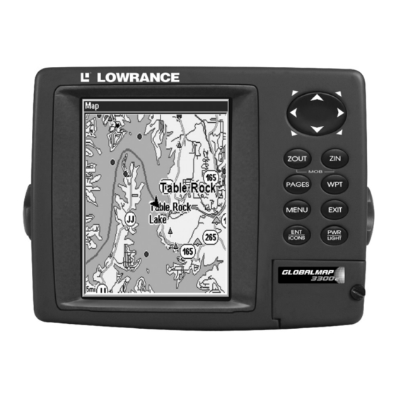
BUT, if you just can't wait to get outside, turn to the one-page Quick Reference on page 40. Keyboard GlobalMap 3300C GPS unit, front view, showing full map, keyboard and access door for the MMC slot. 1. PWR/LIGHT (Power & Light) – The PWR key turns the unit on and off and activates the backlight. -
Page 34: Power/Lights (Turn Unit On And Off)
3. MENU – Press this key to show the menus and submenus, which allow you to select a command or adjust a feature. This also accesses search functions for streets, intersections, addresses and highway exits. 4. ARROW KEYS – These keys are used to navigate through the menus, make menu selections and move the map cursor. - Page 35 Point of Interest or map cursor location; or after you reach the end of a route or trail. GPS Setup command: sets various GPS receiver options. System Setup command: sets general configuration options. Sun/Moon Calculations command: finds the rising and setting time...
-
Page 36: Satellite Status Page
Trip Calculator command: shows trip status and statistics. Timers command: controls the up timer, down timer and alarm clock settings. Browse MMC Files command: this allows you to view the installed MMC card and the files it contains. Pages The unit has three Page displays that represent the three major oper- ating modes. - Page 37 You can use this to see which satellites are obstructed by obstacles in your immediate area if the unit is facing north. The GPS receiver is tracking satellites that are in bold type. The re- ceiver hasn't locked onto a satellite if the number is grayed out, there- fore it isn't being used to solve the position.
-
Page 38: Navigation Page
This also gives you an indicator of the fix quality the unit currently has. The smaller the position error number, the better (and more ac- curate) the fix is. If the position error flashes dashes, then the unit hasn't locked onto the satellites, and the number shown isn't valid. (For details, see the Customize Page Displays entry in Sec. - Page 39 NOTE: Remember, when the Speed, Track and Position information dis- plays are flashing, satellite lock has not been achieved and no posi- tion fix has been determined. A question mark will also flash on the present position arrow in the center of the compass rose. Speed (ground speed) is the velocity you are making over the ground.
-
Page 40: Map Page
The cross track error range is shown on the compass rose as a wide, white, corridor enclosing the course line. The outer edges of this white corridor represent lines that show the current cross track error range. The default for the cross track error range is 0.20 miles. For example, if the present position symbol touches the right cross track error line, then you are 0.20 miles to the right of the desired course. - Page 41 The arrow in the center of the screen is your present position. It points in the direction you're traveling. The solid line extending from the back of the arrow is your plot trail, or path you've taken. The map zoom range is the distance across the screen. This number shows in the lower left corner of the screen.
-
Page 42: Background Map Vs. Mapcreate Map Content
Map Pages with high-detail MapCreate map of an urban area loaded on the MMC. At left, arterial streets are visible at the 4 mile zoom range. Center, numerous dots representing Points of Interest are visible at the 2 mile range, along with minor streets. Right, at the 0.4 mile zoom, you can see an interstate highway with an exit, major and minor streets as Background map vs. - Page 43 NOTE: Available through LEI Extras (look inside back cover for accessory ordering information), FreedomMaps are pre-made maps that con- tain all of the same information available in a custom MapCreate map, without any of the work of preparation. Interstate Minor Streets Marker School POI...
-
Page 44: Resize Window Command
The Pages Menu also offers several map display options under the Map |← or → to Page category. To access them, press |↓ to Op- PAGES tion| EXIT Digital Data map page option. In pages that have two major windows (such as two maps) you can tog- back forth between... - Page 45 1. From any two-window display, press 2. Four flashing arrows appear along the centerline dividing the two windows. Press an arrow key perpendicular to the centerline to adjust the window widths. Press an arrow key parallel to the centerline to switch between horizontal and vertical layout.
-
Page 46: Basic Gps Quick Reference
Basic GPS Quick Reference Start outdoors, with a clear view of the open sky. As you practice, try navigating to a location at least a few blocks away. While you're learning, navigation in too small an area will constantly trigger arrival alarms. 1. -
Page 47: Find Your Current Position
Find Your Current Position Finding your current position is as simple as turning the unit on. Un- der clear sky conditions, the unit automatically searches for satellites and calculates its position in approximately one minute or less. NOTE: "Clear sky" means open sky, unobstructed by terrain, dense foliage or structures. -
Page 48: Selecting Any Map Item With The Cursor
Distance measured by cursor Cursor line The selected wreck (the Empress) to the southeast is 12.81 miles away. Selecting Any Map Item With the Cursor 1. Use the zoom keys and the arrow keys to move around the map and find the item you wish to select. - Page 49 NOTE: This example requires the Point of Interest (POI) database included with a high detail MapCreate 6 custom map. After the unit has acquired a position: 1. Press |↓ to POI-R 2. You could search the entire restaurant category, but in this example we will narrow our search.
- Page 50 POI information screen on fast food restaurant nearest this position. Screen shows name, street address, phone number, latitude/longitude, distance to restaurant and its compass bearing. Figure at left shows Go To waypoint command; right figure shows Find On Map command. 6.
-
Page 51: Set A Waypoint
NOTE: Search works from mapping and POI data loaded in the unit. If you do not have a high-detailed custom map (containing POI data) for the area you are searching loaded on the MMC, you may not find anything. Set a Waypoint A waypoint is simply an electronic "address,"... -
Page 52: Create Waypoint On Map
Step 1. Step 3. Sequence for setting a waypoint. Step 1: while traveling, quickly press WPT twice to call up Find Waypoint screen (seen in Step 2) and set a point. Step 3: a message says the waypoint has been saved. Step 4: ve- hicle continues on its way;... -
Page 53: Navigate To A Waypoint
4. Press ↓ to ONGITUDE change the first character, then press → to the next character and repeat until the longitude is correct. Press previous page display. The waypoint is saved and automatically given a name with a sequential number, such as "waypoint 001." The waypoint symbol and number appear on the map and in the waypoint list. -
Page 54: Set Man Overboard (Mob) Waypoint
Set Man Overboard (MOB) Waypoint One of boating's most terrifying events is having a friend or family member fall overboard. This situation can be deadly on any body of wa- ter — fresh or salt. It's particularly dangerous at night or if you're out of sight of land. -
Page 55: Navigate To Cursor Position On Map
The man overboard position is also stored in the waypoint list for future reference. It can be edited the same as any other waypoint. This pre- vents the inadvertent loss of the current Man Overboard position. To cancel navigation to MOB, press |↓... -
Page 56: Navigate To A Point Of Interest
The 30-mile zoom figure at left clearly shows the red course line connect- ing your current position to your destination. The 30-mile zoom, center, shows both current position and direction to destination on screen. The Navigation Page, right, will also show navigation information. To stop navigating to the cursor, use the Cancel Navigation command: press |↓... - Page 57 The unit is set at the factory to automatically create and record a trail while the unit is turned on. The unit will continue recording the trail until the length reaches the maximum trail point setting (default is 2,000, but the unit can record trails 9,999 points long). When the point limit is reached, the unit begins recording the trail over itself.
-
Page 58: Displaying A Saved Trail
New trail, named "Trail 4," is created when Trail 3 is made inactive. Any new travel will be recorded in this trail, which is active and visi- ble. Trails do not need to be visible in order to be active. You can save and recall up to 10 different plot trails, which can also be copied to your MMC for archiving or for transfer to your MapCreate software. -
Page 59: Navigating Trails
To turn on trail display: 1. Press MENU MENU 2. Press ↓|↓|↓ to enter the Saved Trail list, then use ↑ or ↓ to select the desired Trail Name| 3. Press ↓ to ISIBLE EXIT EXIT EXIT EXIT Navigating Trails There are three methods for following a trail: visual trailing, navigating a trail (forward) and backtracking a trail (backward). - Page 60 NOTE: If you are already located at or near the beginning of your trail, the arrival alarm will go off as soon as you hit Enter. Just press clear the alarm and proceed. 5. Now, begin moving and follow your unit. 6.
- Page 61 much turn off the visible trail option. The Navigation Page will show only the red course line, unless you are recording a new trail. The bear- ing arrow on the compass rose points to the next waypoint on the trail. As you travel, the arrival alarm will go off when you near a trail way- point, and the bearing arrow on the compass rose will swing around and point to the next trail waypoint.
-
Page 62: Navigate A Back Trail (Backtrack, Or Reverse)
Navigate a Back Trail (backtrack, or reverse) 1. Press MENU MENU 2. Press ↓|↓|↓ to enter the Saved Trail list, then use ↑ or ↓ to select the desired Trail Name| 3. Press ↓ to ELETE 4. Press → to EVERSE begins showing navigation information along the trail, in reverse. - Page 63 The Transfer My Data submenu asks if you want to save data to the MMC or load data from the MMC into the unit's memory. 2. The Transfer My Data menu includes a message which tells you if an MMC is present or not. If no MMC is present, you must first insert a card into the unit in order to activate the Load or Save commands.
-
Page 64: Cancel Navigation
4. Loading to unit memory: There may be more than one GPS Data File (*.USR) on the card. To select a file, press to activate the selec- tion box, use ↓ or ↑ to highlight the file, then press to accept the selection. -
Page 65: Sec. 4: Advanced Gps Operations
Advanced GPS Operations Find Distance From Current Position To Another Location 1. While on the Map Page press: 2. Center your cursor over the position you want to find the distance to. A rubber band line appears, connecting your current position to the cursor's location. -
Page 66: Icons
Icons Icons are graphic symbols used to mark some location, personal point of interest or event. They can be placed on the map screen, saved and re- called later for navigation purposes. These are sometimes referred to as event marker icons. This unit has 42 different symbols you can pick from when creating an icon. -
Page 67: Delete An Icon
Delete an Icon You can delete all the icons at one time, you can delete all icons repre- sented by a particular symbol, or you can use the cursor to delete a se- lected icon from the map. 1. Press |↓... -
Page 68: Routes
Routes A route is a series of waypoints, linked together in an ordered sequence, that's used to mark a course of travel. You can visualize a route as a string of beads: The beads represent waypoints and the string repre- sents the course of travel connecting waypoint to waypoint. - Page 69 Route Planning command on Main Menu, left, will open the Route List screen, right. 2. If necessary, press ↑ to select , then press . (To add to OUTE an existing route, press ↓ or ↑ to route name| 3. Press ↓ to |↓...
- Page 70 Route creation sequence, from left: Fig. 1. Set route waypoint (1) at the cove entrance. Fig. 2. Move cursor northeast to set point (2) at channel entrance. Fig. 3. With point (2) set, move cursor southeast to mark channel exit with waypoint (3). In figures 2 and 3, notice the rubber band line extending from the previously set waypoint to the cursor.
-
Page 71: Delete A Route
8. To save your route, press screen, with the route automatically named "Route 1" and stored in the unit's internal memory. You can edit the route and run other commands, but if you are finished with the route for now, return to the last page displayed by pressing EXIT EXIT... -
Page 72: Navigate A Route
1. From the AVIGATION press |↓ to MENU MENU 2. Press ↓ to route name| to select a waypoint, then press 3. Use ↓ and ↑ to select a command from the Edit Route Waypoints menu and press route by clicking on a map location with the cursor. Add Waypoint calls up the Waypoint List so you can insert a waypoint from the list. -
Page 73: Navigate A Route In Reverse
Route Planning command on Main Menu, left; Routes menu, center; Edit Route menu, right. Navigate Route command is selected. 2. Press ↓ to select route name| 3. Upon arrival at your destination, cancel navigation: press |↓ to MENU MENU The following figures show what the Navigation Page and Map Page look like while navigating a route. -
Page 74: Trails
Figure 1. Navigating along a route: Fig. 1 shows the Navigation Page at the start of a route, heading straight for the first waypoint (Wpt 1). In Fig. 2, the traveler has arrived at Wpt 1; the arrival alarm has been triggered and the bearing arrow on the compass rose has turned to point toward Wpt Figure 3. -
Page 75: Edit A Trail Name
Tip: You can also delete all trails at once: 1. Press MENU 2. Press → to Edit a Trail Name To edit a trail name: press . Press ↑ or ↓ to change the first character, then press name| → to the next character and repeat until the name is correct. Press then EXIT EXIT... -
Page 76: Utilities
At left, Edit Trail Menu with Pattern option selected. At right, edited Utilities Utilities are useful tools for traveling or for outdoor activities. Alarm Clock To get to the alarm clock menu: press LARM LOCK Sun/Moon Rise & Set Calculator To get to the Sun/Moon menu: press ALCULATIONS Trip Calculator... -
Page 77: Edit A Waypoint (Name, Symbol Or Position)
To delete a waypoint from the map: 1. Use the arrow keys to select the waypoint with the cursor. 2. Press |→ to the previous page and clear the cursor, press To delete all waypoints at one time: press |↓ to ETUP ELETE to the previous page, press... -
Page 78: Selecting A Waypoint
Selecting a Waypoint To select a waypoint on the map (for navigating to, for editing, etc.,) use the arrow keys and center the cursor over the waypoint. A highlighted halo will appear around the waypoint. Set a Waypoint by Average Position This feature sets a waypoint at the current position after taking several position readings and averaging them. -
Page 79: Sec. 5: System & Gps Setup Options
Section 5: System & GPS Setup Options Alarms This unit has several GPS alarms. The factory default setting has all of these but the anchor alarm turned on. You can turn the alarms off and on and change their distance settings. You can set an arrival alarm to flash a warning message and sound a tone when you cross a preset distance from a waypoint. -
Page 80: Check Mmc Files And Storage Space
3. To change distance settings, scroll gory, then press → | ↓ to change the first character, then press → to the next character and repeat until the name is correct. 4. When your adjustments are finished, return to the last page dis- played by repeatedly pressing IMPORTANT ALARM NOTES: Anchor Alarm - The anchor alarm may be triggered even when... -
Page 81: Configure Nmea
Menus for changing Com Port settings. For connectors and wiring information for another device, see page 20. For assistance in configuring the unit to communicate with another device, consult the factory; customer service phone numbers are in the back of this manual. Also see the entry below for Configure NMEA. To set Com Port Configuration: 1. -
Page 82: Coordinate System Selection
• GGA transmits time, position, and fix related data. • GSA and GSV transmits fix mode, DOP values, and satellites in view information. • DBT transmits the depth below the transducer. • DPT transmits the depth • MTW transmits the water temperature. •... -
Page 83: Setup Loran Td
(Universal Transverse Mercator) projection; MGRS (Standard); MGRS (Standard + 10); Map Fix; Loran TD; British, Irish, Finnish, German, New Zealand, Swedish, Swiss, Taiwan and Greek grid systems. UTM's are marked on USGS topographic charts. This system divides the Earth into 60 zones, each 6 degrees wide in longitude. British, Irish, Finnish, German, New Zealand, Swedish, Swiss, Taiwan, and Greek grid systems are the national coordinate system used only in their respective countries. -
Page 84: Map Fix
Map Fix Map Fix is used with charts or maps. This system asks for a reference position in latitude/longitude, which you take from a marked location on the map. It then shows the present position as distance on the map from that reference point. -
Page 85: Customize Page Displays
Press → to ELECT Select the waypoint (or a landmark of POI) that you saved the reference point under and press screen with the command returns to the Configure Map Fix menu. Finally, press this menu. Now press ↑ to list and press tance from the reference point you chose. -
Page 86: Simulating Trail Or Route Navigation
GPS Setup Menu, left; GPS Simulator menu, center. Map Page showing Track and Speed steering arrow indicators, right. In this example, you are "traveling" across Mudisland Point on a track of 19º at a speed of 50 miles per hour. Make the desired settings, then turn the simulator on by highlighting GPS S IMULATOR... -
Page 87: Initialize Gps
tion begins. Press press ↑ to increase speed to the desired setting. 4. Press to turn off the steering and speed boxes. The unit will now EXIT automatically "steer" along the trail or route. When you arrive at your "destination," cancel navigation as you normally do. Tip: You can pick any spot on the map to begin your simulation session by using the Initialize GPS command. -
Page 88: Map Data
Map Data This menu lets you turn the map off, if desired (which turns the map screen into a GPS plotter); turn off or on the pop-up map info boxes; draw the map boundaries or boxes around the areas of high detail; or fill land areas with gray. -
Page 89: Fill Water With White
Fill Water With White From the Map Page, press . With the option highlighted, press ATER HITE (turn on) and uncheck it (turn off.) After the option is set, press to return to the page display. EXIT EXIT Map Overlays (Range Rings; Lat/Long Grid) The map screen can be customized with four range rings and/or grids that divide the plotter into equal segments of latitude and longitude. -
Page 90: Map Detail Category Selection
3. To return to the last page displayed, press A list of the datums used by this unit is in the back of this manual. GPS Setup Menu, left, Map Datum Menu, right. Map Detail Category Selection This menu determines which of the mapping features are shown on the screen. -
Page 91: Map Orientation
Map Orientation By default, this receiver shows the map with north always at the top of the screen. This is the way most maps and charts are printed on paper. In Track Up mode, map shows "N" and arrow to indicate north. Map orientation at left is shown in north up and at right, track up. -
Page 92: Navionics Charts
Map Menu, left; Map Orientation menu with the North Up map orientation option selected, right. NOTE: In North Up and Course Up, the present position arrow appears in the center of the map page. In Track Up, the position arrow appears centered in the lower third of the page. -
Page 93: Port Information
These figures show menu sequence (from left to right) for selecting a Navionics chart for the South Chesapeake Bay area. 3. To turn off a Navionics chart, From the Map Page, press |↓ to , then press OWRANCE Port Information Navionics charts contain Port Services information, represented by an- chor icons on the map display. -
Page 94: Tidal Current Information
3. To scroll through the Service Categories window: press ↑ or ↓ to see the types of services available. As you highlight a different category, the list in the lower window changes. To return to the Map Page, press EXIT EXIT 4. - Page 95 Pop-up name box Navionics chart showing Tidal Current Station icon selected by cur- sor. In this example, the current is flowing to the west at 0.2 kn. 2. Press to display the Tidal Current Information screen. The Tidal Current Information screen displays daily tidal current data for this station on this date at the present time.
-
Page 96: Tide Information
1. Use → and ← to highlight month, day or year, then press 2. Use ↑ and ↓ to select the desired month, day or year, then press To clear the information screen, press Tide Information Navionics charts represented at large zoom ranges by a box icon with the letter "T."... -
Page 97: Pop-Up Help
Tide Information screen. The Tide Information screen displays daily tidal data for this station on this date at the present time. The graph at the top of the screen is an approximate view of the tidal range pattern for the day, from midnight (MN), to noon (NN) to midnight (MN). -
Page 98: Position Pinning
System Setup Menu, left, with Pop-up Help command highlighted. At right, this example shows the Pop-up Help message for the Overlay Data command, located on the Map Page menu. Position Pinning When you are standing still or moving at extremely slow speed, a GPS receiver can have trouble determining the direction you are traveling. -
Page 99: Require Waas
System Menu with Reset Options command selected. Require WAAS You can force the unit to require WAAS for reporting a valid position. (The default setting, off, uses WAAS automatically, but doesn't require it to yield a position.) Here's how to turn it on and off: 1. - Page 100 Once in the Screen menu: To adjust the display's contrast: slider bar is already selected. Press → or ← to move the ONTRAST bar. The left end of the scale is minimum contrast; the right end is maximum contrast. Screen Command, left, and Screen Menu with Contrast bar selected, right. To adjust the display's brightness: Press ↓...
-
Page 101: Set Language
Set Language This unit's menus are available in 10 languages: English, French, Ger- man, Spanish, Italian, Danish, Swedish, Russian, Dutch and Finnish. To select a different language: 1. Press MENU MENU 2. Press ↓ to ANGUAGE 3. Use ↓ or ↑ to select a different language and press now appear in the language you selected. -
Page 102: Software Version Information
That can result in the alarm repeatedly going on and off. If you want, you have the option of turning off the WAAS Acquired/Lost alarm with- out affecting how the unit uses WAAS. Here's how: 1. Press MENU MENU 2. With the option highlighted, press check it (turn on.) After the option is set, press the page display. -
Page 103: Track Smoothing
Sounds command, left. At right, the Sounds menu. Once in the Sounds menu: To set Key Press Sounds: With the option highlighted, press check it (turn on) and uncheck it (turn off.) After the option is set, press to return to the page display. EXIT EXIT To set Alarm Sounds: Press ↓... -
Page 104: Trail Options
Trail Options There are several options you can use with trails. Some affect all trails, other options can be applied to a particular trail. You can change the way trails are updated, display or hide trails, create a new trail, delete a trail, etc. -
Page 105: Trail Update Rate (Time, Distance)
unit "drops" a plot point (trail waypoint) onto the trail. This conserves plot trail points. If a plot trail uses all of the available points allotted to it, the beginning points are taken away and placed at the end of the trail. From the Trails Menu, press ↓... -
Page 106: New Trail
Edit Trail menu. New Trail To manually start a new trail, in the Trails Menu, make sure RAIL is highlighted and press Trail Visible/Invisible and Other Trail Options The name, maximum number of points in the trail, activity, and visi- bility are all changed on the Edit Trail menu screen. -
Page 107: Units Of Measure
Main Menu with Transparency command selected. To adjust Menu Transparency level: Press |↓ to . The slider bar MENU MENU RANSPARENCY RANSPARENCY appears. Press ↑ or ↓ to move the bar. The lower end of the scale makes the menus opaque; the upper end is maximum transparency. Units of Measure This menu sets the speed and distance (statute or nautical miles, me- ters), depth (feet, fathoms, or meters), temperature (degrees Fahrenheit... - Page 108 Notes...
-
Page 109: Sec. 6: Searching
NOTE: The background map loaded in your unit lets you to search for U.S. Interstate Highway exits and exit services, as well as some land features, including cities and lakes. For a full set of searchable land features, including landmarks, streets, addresses and Points of In- terest, you must load your own high-detail custom map produced with our MapCreate 6 software. -
Page 110: Find Addresses
In search results, the distance and bearing to the selected item will be calculated from the current position. In the case of a cursor search, the search results show distance and bearing from the cur- sor, but an individual waypoint's information screen shows distance and bearing from the current (or last known) position. - Page 111 Find Address menu, left; Find Street menu, center, with Find By Name field active; street name entry complete, right. 5. To enter a city name, press ↓ to want to find addresses only within a particular city. This option is de- signed so you can limit an address search to a single city if necessary (see the following note).
- Page 112 6. When the necessary search fields are filled in, press ↓ to . Your unit asks you to wait while it searches for the address. DRESS (If an address is not in the database, a message appears saying the ad- dress could not be found.) 7.
-
Page 113: Find Any Item Selected By Map Cursor
Left, Map Page showing location of the address on the map, high- lighted by cursor. Center, this address is a business in the POI data- base, so you can display the POI information window, then navigate to it. At right, this address is not in the POI database, so the Waypoint key will not display any information for this address. - Page 114 Find Highway Exits command, left, and Find Exit menu, right. 2. First, select a highway name by pressing , which calls up the Find By Name menu. There are two highway search options: A. You can spell out the highway name in the top selection box. Press ↑ or ↓ to change the first letter, then press →...
- Page 115 Find Exit menu, with an exit selected in the Exit List. 4. In the Exit Information screen you have two choices. A. Press navigate or "go to" the exit. B. Press →| "Go To Exit" option, left, "Find On Map" option, right. Tip: You can also look up some additional information on the Exit Serv- ices located near this exit.
-
Page 116: Find Map Places Or Points Of Interest (Poi)
Exit Information screen, left; general location and amenities information, at right. Find Map Places or Points of Interest (POI) ↓ ↑ 1. Press , press to select a map place or POI category, then . (To narrow your search, press → or ← to select a subcate- press gory before pressing .) You will be given two options;... - Page 117 Find by Nearest option, left, Calculating screen, center, POI list, right. 3. Search by name of POI. Press . There are two options: A. You can spell out the POI in the top selection box. Press ↑ or ↓ to change the first letter, then press →...
-
Page 118: Find Streets Or Intersections
"Go To" POI option, left, "Find on Map" POI option, right. Find Streets or Intersections Find a Street 1. From the Map Page, press |↓ to and the Find MENU TREETS Streets Menu appears. Find Streets command, left, Find Streets menu, right. 2. - Page 119 Find Street By Name menu. Spell out name in the top box, or select from the list in the lower box. 3. The Find Streets menu reappears with the street you're searching for in the First Street box. (In this example, it's I-35.) To search for that street, press ↓...
- Page 120 Map Page showing results of a street search. The cursor points to the located street. If you want to navigate to the found street at the cursor location, just press MENU EXIT Find an Intersection You must enter one street in the First Street dialog box and enter the next street in the Second Street dialog box.
- Page 121 5. The Find Streets menu reappears with the first and second street dialog boxes filled in. In this example, we selected I-44 as our second street. You could now use similar techniques to select a city or Zip code, but your search will probably be faster if you leave those boxes blank. (You can specify a city and/or Zip code later on to narrow the search, if the resulting list is too long.) Find Intersection command highlighted, left.
-
Page 122: Find Waypoints
If you want to navigate to the found intersection, just press MENU EXIT Find Waypoints 1. Press |↑ to AYPOINTS 2. If searching for the waypoint By Name, press . If searching for the Nearest waypoint, press ↓ to . (To search by name, |ENT EAREST jump to step 5.) - Page 123 4. To see location information on the closest (highlighted) waypoint, press and the Waypoint Information screen appears. (If you wanted to, you could select another waypoint from the list with the ↑ or ↓ keys.) A. To navigate to the waypoint, press command is already highlighted.) The unit will show navigation in- formation to the waypoint.
- Page 124 Find By Name menu, left. Waypoint Information screen, center. At right, the found waypoint is highlighted by the cursor on the Map Page. A. To navigate to the waypoint, press . (Go To Waypoint com- mand is already highlighted.) The unit will show navigation infor- mation to the waypoint.
-
Page 125: Sec. 7: Supplemental Material
Section 7: Supplemental Material Datums Used by This Unit WGS 1984 Default Adindan Mean for Ethiopia, Sudan Adindan Burkina Faso Adindan Cameroon Adindan Ethiopia Adindan Mali Adindan Senegal Adindan Sudan Afgooye Somalia Ain el Abd 1970 Bahrain Ain el Abd 1970 Saudi Arabia Anna 1 Astro 1965 Cocos Islands... - Page 126 Chua Astro Paraguay Corrego Alegre Brazil Dabola Guinea Djakarta (Batavia) Indonesia (Sumatra) DOS 1968 New Georgia Islands (Gizo Island) Easter Island 1967 Easter Island European 1950 Mean for Austria, Belgium, Denmark, Finland, France, West Germany, Gi- braltar, Greece, Italy, Luxembourg, Neth- erlands, Norway, Portugal, Spain, Sweden, Switzerland...
- Page 127 Naparima BWI Trinidad & Tobago North American 1927 Mean for Antigua, Barbados, Barbuda, Caicos Islands, Cuba, Dominican Republic, Grand Cayman, Jamaica, Turks Islands North American 1927 Mean for Belize, Costa Rica, El Sal- vador, Guatemala, Honduras, Nicaragua North American 1927 Mean for Canada North American 1927 Mean for CONUS...
- Page 128 Point 58 Sweden Santo (DOS) 1965 Espirito Santo Island Sao Braz Azores (Sao Miguel, Santa Maria Islands) Sapper Hill 1943 East Falkland Island Schwarzeck Nambia Selvagem Grande Salvage Islands SGS 85 Soviet Geodetic System 1985 South American 1969 Mean for Argentina, Bolivia, Brazil, Chile, Colombia, Ecuador, Guyana, Paraguay,...
-
Page 129: Fcc Compliance
This device complies with Part 15 of the U.S. Federal Communi- cations Commission (FCC) Rules. Operation is subject to the fol- lowing two conditions: (1) this device may not cause harmful in- terference, and (2) this device must accept any interference re- ceived, including interference that may cause undesired opera- tion. - Page 130 Notes...
-
Page 131: Index
Accessories, 1, 3, 4, 5, 6, 11, 21, 22, 26, 37, 56, 103 Sec. 2, Installation & Accessories, 11 Alarm Clock, 70 Alarms, 29, 40, 54, 55, 56, 68, 73, 74, 80 Anchor Alarm, 73, 74 Antenna, 1, 3, 4, 11, 12, 13, 15, 19, 22, 23, 40, 41, 123 Arrival Alarm, 40, 54, 55, 56, 68, 73, 74, Backlights / Lighting, 2, 27... - Page 132 57, 58, 62, 74, 86 Navigating, 10, 40, 47, 48, 49, 50, 53, 54, 55, 56, 61, 66, 67, 74 A Route, 66, 67 A Trail, 53 Cancel, 29, 40, 49, 50, 54, 56, 58, 67 To Cursor Position, 49 To Icon, 61 Nearest, 42, 43, 44, 47, 103, 110, 111, NMEA, 3, 11, 14, 15, 16, 17, 18, 19, 20,...
- Page 133 Utilities, 27, 30, 70 WAAS, 3, 4, 6, 7, 11, 31, 93, 95, 96 Require WAAS, 93 Waypoints, 2, 3, 5, 8, 9, 24, 28, 29, 32, 33, 34, 40, 42, 43, 44, 45, 46, 47, 48, 49, 50, 55, 56, 60, 62, 63, 64, 65, 66, 67, 68, 70, 71, 72, 73, 74, 77, 78, 79, 80, 81, 84, 85, 92, 95, 99, 103, 104, 106, 107, 110, 111, 116, 117, 118...
- Page 134 Notes...
- Page 135 LOWRANCE DATABASES LICENSE AGREEMENT THIS IS A LEGAL AGREEMENT BETWEEN THE END-USER WHO FIRST PURCHASES THIS PRODUCT AS A CONSUMER ITEM FOR PERSONAL, FAMILY, OR HOUSEHOLD USE ("YOU") AND LOWRANCE ELECTRONICS, INC., THE MANUFACTURER OF THIS PRODUCT ("WE", "OUR", OR "US"). USING THE PRODUCT ACCOMPANIED BY THIS LICENSE AGREEMENT CONSTITUTES ACCEPTANCE OF THESE TERMS AND CONDITIONS.
- Page 136 DATABASES LIMITED WARRANTY "We", "our", or "us" refers to Lowrance Electronics, Inc., the manufacturer of this product. "You" or "your" refers to the first person who purchases the prod- uct as a consumer item for personal, family, or household use. The Databases Limited Warranty applies to the one or more databases that your product may contain.
- Page 137 LOWRANCE ELECTRONICS FULL ONE-YEAR WARRANTY "We," "our," or "us" refers to LOWRANCE ELECTRONICS, INC., the manufacturer of this product. "You" or "your" refers to the first person who purchases this product as a consumer item for personal, family or household use. We warrant this product against defects or malfunctions in materials and workmanship, and against failure to conform to this product's written specifications, all for one (1) year from the date of original purchase by you.
-
Page 138: How To Obtain Service
How to Obtain Service… …in the USA: We back your investment in quality products with quick, expert service and genuine Lowrance parts. If you're in the United States and you have technical, return or repair questions, please contact the Factory Customer Service Department. - Page 139 Accessory Ordering Information for all countries To order Lowrance accessories such as power or adapter cables, please contact: 1) Your local marine dealer or consumer electronics store. Most quality dealers that handle marine electronic equipment or other consumer electronics should be able to assist you with these items. To locate a Lowrance dealer near you, visit our web site, www.lowrance.com and look for the Dealer Locator.
- Page 140 Visit our web site: Lowrance Pub. 988-0156-021 © Copyright 2004 All Rights Reserved Printed in USA 020604 Lowrance Electronics, Inc.