
Related Manuals for Contec SCP-8550-LLV


Summary of Contents for Contec SCP-8550-LLV
- Page 1 SBC Series Single Board Computer 6U CompactPCI with LAN*2, Video SCP-8550-LLV User’s Manual CONTEC CO.,LTD.
- Page 2 Check Your Package Thank you for purchasing the CONTEC product. The product consists of the items listed below. Check, with the following list, that your package is complete. If you discover damaged or missing items, contact your retailer. Product Configuration List CPU board [SCP-8550-LLV] …1...
-
Page 3: Copyright
No part of this document may be copied or reproduced in any form by any means without prior written consent of CONTEC CO., LTD. CONTEC CO., LTD. makes no commitment to update or keep current the information contained in this document. The information in this document is subject to change without notice. -
Page 4: Table Of Contents
Storage .............................. 4 Disposal ............................4 SYSTEM REFERENCE Specification ............................5 Power Management Features ........................7 Power Requirements..........................7 Power Consumption ......................... 7 Connector & Jumper Location ........................ 8 Daughter Board ..........................8 CPU Board............................9 Block Diagram............................10 SCP-8550-LLV... - Page 5 PS/2 Mouse Connector ..........................23 PS/2 Keyboard Connector ........................23 Printer Connector ...........................24 LAN1 connector.............................25 LAN2 connector.............................25 USB1 - 4 Connectors ..........................26 SER1/SER2 connectors .........................26 DVI-D Connector...........................27 VGA Connector .............................28 RAS Connector ............................28 JUMPER SETTING Clear ROM: JP1 .............................29 Clear CMOS: JP2...........................29 SCP-8550-LLV...
- Page 6 Interrupters............................. 43 BIOS SETUP Introduction ............................45 keystrokes .............................. 45 Main Menu ............................46 Advanced Menu............................. 48 Security Menu............................58 Power Menu............................59 PC Health Menu ............................ 61 Boot Menu ............................. 63 Exit Menu .............................. 64 POST Codes ............................66 SCP-8550-LLV...
- Page 7 SCP-8550-LLV...
-
Page 8: Introduction
Option List PCPM-16F Pentium M 1.6GHz (with heat sink-fan) PCPMC-13F Celeron M 1.3GHz (with heat sink-fan) Memory (PC2700 DDR SDRAM DIMM, No parity) PC-MDD256-184A DDR SDRAM DIMM, 256MB PC-MDD512-184A DDR SDRAM DIMM, 512MB OTHER SCP-RPIO-01 Rear Panel I/O Board SCP-8550-LLV... -
Page 9: Customer Support
You can download updated driver software and differential files as well as sample programs available in several languages. Note! For product information Contact your retailer if you have any technical question about a CONTEC product or need its price, delivery time, or estimate information. Limited One Year Warranty CONTEC Industrial CPU board is warranted by CONTEC CO., Ltd. -
Page 10: Safety Precautions
Handling Precautions CAUTION Do not modify the product. CONTEC will bear no responsibility for any problems, etc., resulting from modifying this product. Do not strike or bend the board. Otherwise, the board may malfunction, overheat, cause a failure or breakage. -
Page 11: Environment
Wrap it in the packing material, then put it in the box. Store the package at room temperature at a place free from direct sunlight, moisture, shock, vibration, magnetism, and static electricity. Disposal When disposing of the product, follow the disposal procedures stipulated under the relevant laws and municipal ordinances. SCP-8550-LLV... -
Page 12: System Reference
Reset mode : Input to general purpose I/O of the external signal. General-purpose I/O 3ch optical isolated inputs and outputs, 15Pin D-SUB(FEMALE) x1 Monitoring of the temperature of CPU and board, power supply voltage, and fan Hardware Monitor speed SCP-8550-LLV... - Page 13 *5: Access LED blinks at the time of access to on board HDD and CF card. It does not blink at the time of access to the drive connect to IDE signal of J4, J5 connectors. (SCP-RPIO-01 has the access LED of the device that connected to the IDE port of J4, J5 connectors.) SCP-8550-LLV...
-
Page 14: Power Management Features
Your system requires a clean, steady power source for reliable performance of the high frequency CPU on the SCP-8550-LLV Industrial CPU board, the quality of the power supply is even more important. For the best performance makes sure your power supply provides a range of 4.75 volts minimum to 5.25 volts maximum DC power source. -
Page 15: Connector & Jumper Location
2. System Reference Connector & Jumper Location Daughter Board Back side CF slot SER2 connector Printer port connector S1: CF master/ slave selector, general-purpose SW Unused connector connector CF slot On-board HDD connector Figure 2.1. Connector & Jumper Location (Daughter Board) SCP-8550-LLV... -
Page 16: Cpu Board
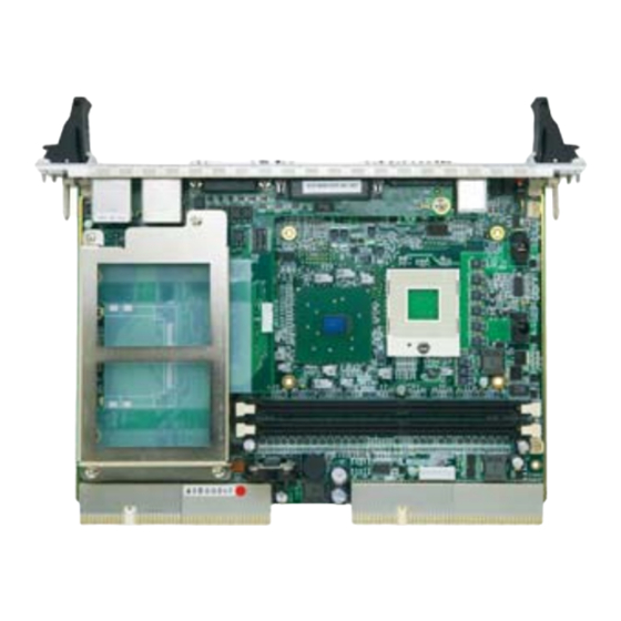
DVI connector External Battery connector VGA connector DIMM1/2: 184 pin DDR RAM connector LAN1 connector & USB 3/4 connector LAN2 connector & USB 1/2 connector JP1: Clear CMOS JP2: Clear CMOS Figure 2.2. Connector & Jumper Location (CPU Board) SCP-8550-LLV... -
Page 17: Block Diagram
Sil164 USBX4 PIDE CPCI/J5 82541PI RJ-45 ICH4 10/100/1K 82801DB SIDE CPCI/J4 HUB Link 82562EZ 421 BGA RJ-45 BIOS PCI BUS CPCI/J1 SUPER I/O CPLD CPCI/J5 W83627HF PCI Bridge 2050B CPCI/J2 SER2 SER1 Parallel RS232 RS232 Figure 2.3. Block Diagram SCP-8550-LLV... -
Page 18: Hardware Installation
3. Hardware Installation 3. Hardware Installation This chapter provides information on how to use the jumpers and connectors on the SCP-8550-LLV in order to set up a workable system. Installation procedure Confirm the power supply is off. Install the processor with correct orientation. -
Page 19: Cpu Installation
Main Memory Installation: DIMM1/DIMM2 The SCP-8550-LLV CompactPCI Industrial CPU board supports two dual inline memory module (DDR SDRAM DIMM 184-pin) sockets for a maximum total memory of 2GB. Using the serial presence detect... -
Page 20: On Board Hdd Connector
There is a HDD connector connected to the primary port of IDE on this board. This connector can connect 2.5inch HDD directly. Table 3.1. On board HDD connector Pin No. Function Pin No. Function RESET N.C. DREQ IORDY DACK N.C. PDIAG HD ACT N.C. SCP-8550-LLV... -
Page 21: Hdd Attachment Method
(2) Three screws which are fixing the daughter board are removed. CPCI J1 Connector CPCI J2 Connector Onboard HDDConnector (3) The HDD fixed bracket is made to slide and the connector of HDD is connected to the on board HDD connector. SCP-8550-LLV... - Page 22 The HDD fixed bracket is combined with fall prevention of CF card. At the time of CF card use, please attach the HDD fixed bracket after inserting CF card. When using only CF card (HDD is not used), fall prevention of CF card is possible by attaching only HDD fixed bracket at the same method. SCP-8550-LLV...
-
Page 23: Compact Flash Slot
3. Hardware Installation Compact Flash Slot The CPU board SCP-8550-LLV provides a Compact Flash (CF) slot. This slot is a very small removable mass storage device. It provides compatibility plus True IDE functionality compatible with ATA/ATA-4. Boot from CF card is possible. -
Page 24: Cf Master/Slave Select Switch: S1
6 : OFF, 8 : ON Slave External ATX control Power Connector Table 3.4. External ATX control Power Connector Pin No. Function 5V SBY 5VSB ATX Power Control signal PS-ON (Soft ON/OFF) PS-ON 5VSB (PBTN-IN) PS-ON Housing:XHP-6 (JST) Contact:SXH-001T-P0.6 (JST) N.C. Chipset SCP-8550-LLV... -
Page 25: System Fan Connector: Fan1/Fan2
It is a 2 Pin connector used for external battery. An external battery power for used of real-time clock and CMOS memory. Table 3.6. External Battery Connector 3VSB Pin No. Function CMOS Memory 1kΩ Real-time clock External_battery (3V) Housing: IL-2S-S3L-(N) (JAE) On board Contact: IL-C2-10000 (JAE) Litium battery 1kΩ SCP-8550-LLV... -
Page 26: Cpci Connectors: J1/J2/J4/J5
-STOP -LOCK +3.3V -FRAME -IRDY -TRDY AD18 AD17 AD16 -C/BE2 AD21 +3.3V AD20 AD19 -C/BE3 AD23 AD22 AD26 AD25 AD24 AD30 AD29 AD28 AD27 -REQ +3.3V CLK0 AD31 -RST -GNT -HEALTHY INTP INTS -INTA -INTB -INTC -INTD -12V +12v SCP-8550-LLV... - Page 27 3. Hardware Installation Table 3.8. J2 connector PCLK3 PCLK2 -PRST -PREQ2 -PGNT2 -DEG -FAL -PREQ -PGNT1 PCLK1 -PGNT5 -PREQ0 -PGNT0 PCLK5 PLCK6 -SYSEN -PGNT4 -PREQ5 PCLK4 -PREQ3 -PGNT3 -PREQ4 SCP-8550-LLV...
- Page 28 *1 Secondary IDE port is shared with CF card slot. Therefore, when using CF card, J4 connector can connect only one drive. *2 VGA signals cannot be used together with the front panel VGA connector. *3 These signals are the same signals as the external ATX control power connector. These cannot be used together. SCP-8550-LLV...
- Page 29 *3 SERIAL1/2 port signals cannot be used together with the front panel connectors. *4 Primary IDE port is shared with the IDE port of on board 2.5inch HDD. Therefore, when using the on board 2.5inch HDD, J5 connector can connect only one drive. SCP-8550-LLV...
-
Page 30: Front Panel Connects Configuration
PS/2 Keyboard Connector The CPU board provides a standard PS/2 mini DIN connector for attaching the PS/2(R) keyboard. The PS2 Connector pin definition is shown below: Table 4.2. PS/2 Keyboard Connector Pin No. Function Keyboard Data N.C. Keyboard Clock N.C. SCP-8550-LLV... -
Page 31: Printer Connector
Bi-Directional EPP. A driver from the peripheral manufacturer is required for operation. Bi-Directional High-speed ECP Table 4.3. Printer Connector 25pin D-SUB female connector Pin No. Function Pin No. Function -STROBE -AFEED -ERROR -INIT -SLCT IN BUSY -ACK BUSY SELECT SCP-8550-LLV... -
Page 32: Lan1 Connector
The category-5 cable is required for transmission at 100/1000Mbps. Table 4.5. LAN2 connector Pin No. Function Transmit Link N.C. N.C. N.C. N.C. Right LED: Link LED (Link: Green, Active: Blink) Left LED: Transmit LED (10M: Off, 100M: Green, 1000M: Orange) SCP-8550-LLV... -
Page 33: Usb1 - 4 Connectors
SER1/SER2 connectors SER1 and SER2 are RS-232C standard serial ports. The following table shows the pin assignments of these connectors. The pin assignment: Table 4.7. SER1/SER2 connectors No.4-40UNC Inch thread Pin No. RS-232C Pin No. RS-232C N.C. SCP-8550-LLV... -
Page 34: Dvi-D Connector
4. Front Panel connects configuration DVI-D Connector This connector is DVI-D connector for LCD. The Panel Link type flat panel display of CONTEC is connectable. The pin assignment is shown below. The pin 20 and pin 21 are connecting to Serial1 (SER1) for the touch panel signal. When used this signal, SER1signal (Front panel and inside J5 connector signal) cannot be used. -
Page 35: Vga Connector
N.C. N.C. DDC DATA H-SYNC V-SYNC DDC CLOCK RAS Connector This connector is RAS connector for WDT & general-purpose I/O. The pin assignment is shown below. Table 4.10. RAS Connector RESERVED RESERVED RESERVED RESERVED NCOM PO2/WDT NCOM PI2/IRQ PCOM SCP-8550-LLV... -
Page 36: Jumper Setting
Setup program. The CMOS data is powered by the onboard button cell battery. User can erase the CMOS memory content by short pin2 and pin3 of JP2 together. Table 5.2. Clear CMOS jumper Function Normal(Default) Clear CMOS momory contents SCP-8550-LLV... - Page 37 5. Jumper setting SCP-8550-LLV...
-
Page 38: Ras Functions
General purpose input * Fastening screw: No 4-4UNC inch thread port address: 4000h - 4010h CAUTION 4 Pin NCOM (minus common dedicated to PO2) and 6 pin NCOM (minus common shared by PO0 and PO1) are electrically separated from each other. SCP-8550-LLV... -
Page 39: Watch Dog Timer
: Resets or generates an interrupt at time-up (Port setting). External alarm output : Photo-coupler insulated open-collector output (the output status is set by software). For more information, see the general-purpose I/O specifications. I/O addresses : 4001h - 4005h (WDT port) SCP-8550-LLV... -
Page 40: How To Use The Watchdog Timer
4002h : Stop the WDT timer and cancel the alarm. Out 4003h 0Fh : Set the WDT expiration time to 15sec. Out 4002h A5h : Start and clear the WDT. 4002h : Stop the WDT and cancel the alarm. SCP-8550-LLV... - Page 41 W: Start and clear the WDT Write A5h to start and clear the WDT. WDT counter port (4003h) Figure 6.5. WDT counter port (4003h) W:Writes watchdog timer count data. Write watchdog timer counter expiration time data. → 1sec → 8sec → 15sec → 30sec SCP-8550-LLV...
- Page 42 1: The time set on the WDT expired. General-purpose I/O and Remote Reset The CPU board is equipped with three general-purpose insulated signals each for input and output. The input signals can also be used for interrupt input or remote reset input. SCP-8550-LLV...
- Page 43 [Common] I/O addresses 4000h and 4001h How to Use General-purpose I/O and Remote Reset Event output Output data to port 4001h to set PI0, PI2 or PO2 mode. control Implement input and output with port 4000h. Figure 6.10. Flowchart SCP-8550-LLV...
- Page 44 Table 6.3. RESET: RESET: Reset Input Modes RESET PI2/IRQ (14)'s RESET input Inhibit the remote reset input function of the RAS connector's PI2/IRQ (14) signal. Use as the remote reset input function of the RAS connector's PI2/IRQ (14) signal. SCP-8550-LLV...
-
Page 45: External I/O Circuit
Input (PI 0 - 2) contact RAS connector Figure 6.13. Input Circuit Output Circuit (External circuit) Load (PO 0 - 2) 510 Ω PC817 External power (Max. 30VDC) 2N3904 4.7k Ω (NCOM) RAS connector Figure 6.14. Output Circuit SCP-8550-LLV... -
Page 46: Dip-Sw(S1), Led1/2
SW6, SW8 are CF setting, SW5, SW7 are reserved for system. Reserved User Define CF Slot : 6 : ON, 8 : OFF Master W : LED control LED Illumination (ON=”1”), black (OFF=”0”) Reserved registers 4006h - 400Fh are reserved for the system. SCP-8550-LLV... - Page 47 6. RAS Functions SCP-8550-LLV...
-
Page 48: Cpu Board Resources
Reserved 03BC - 03BF 8 bytes LPT3 03C0 - 03DF 32 bytes Video (VGA) 03E8 - 03EF 8 bytes COM3 03F0 - 03F5, 03F7 8 bytes FDD controller 03F6 1 bytes Primary IDE 03F8 - 03FF 8 bytes COM1 SCP-8550-LLV... -
Page 49: Memory Map
System BIOS E0000 - E7FFF 32KB System BIOS (Available as UMB) D0000 - DFFFF 64KB Available high DOS memory (open to ISA and PCI buses) A0000 - CFFFF 192KB Video memory and BIOS 00000 - 9FFFF 640KB Conventional memory SCP-8550-LLV... -
Page 50: Dma Channels
USB/User available Windows Sound System/User available PS/2 mouse port (if present, else user available) Reserved, math coprocessor Primary IDE (if present, else user available) Secondary IDE (if present, else user available) * Default, but can be changed to another IRQ SCP-8550-LLV... - Page 51 7. CPU Board Resources SCP-8550-LLV...
-
Page 52: Bios Setup
The Save Values commands in the Exit Menu save the values currently displayed in all the menus. To display a sub menu, use the arrow keys to move the cursor to the sub menu you want. Then press <Enter>. A pointer (►) marks all sub menus. SCP-8550-LLV... -
Page 53: Main Menu
[Auto] System Memory XxxKB Extended Memory XxxxxKB (General key operation help) *1 It shows Item Specific Help, if the item has a help information. *2 The “>” mark indicates it has a submenu. Figure 8.1. Main Window (Factory Settings) SCP-8550-LLV... - Page 54 2 Masters 2 Masters, 1 Slave 2 Masters, 2 Slaves CAUTION Do not attempt to change these settings unless you have an installed drive that does not autotype properly (such as an older hard-disk drive that does not support autotyping). SCP-8550-LLV...
-
Page 55: Advanced Menu
[Yes] and exiting BIOS Setup while saving the changes you made. This field reverts to [No] automatically the next time you invoke BIOS Setup. Before reinstalling the OS, be sure to set the field to [Yes]. Installed O/S Select the operating system you use.([WinXP]or[Win2000] ) Large Disk Access Mode Normally, set to "DOS". SCP-8550-LLV... - Page 56 [Write Protect] Figure 8.3. Cache Memory Features Window (Factory Settings) Please use it basically by the default setting. Cache System BIOS Enables or disables all memory caching. Cache System BIOS area and another Enables or disables specific area’s cache. SCP-8550-LLV...
- Page 57 Exit PCI Features > PCI IRQ Figure 8.5. PCI Features Window (Factory Settings) PCI IRQ Displays the PCI IRQ setup submenu. You can assign IRQs to individual PCI IRQ lines. All PCI slots are connected to IRQ10 by default. SCP-8550-LLV...
- Page 58 Enabled when a catastrophic IDE failure is about to happen IDE Primary Cable 40 conductor 40 conductor Cable:ATA33 IDE Secondary Cable 80 conductor 80 conductor Cable:ATA33 - 100 Auto Auto Detect by BIOS SCP-8550-LLV...
- Page 59 Thus the AGP display becomes the primary display. Internal DDC ROM Disabled Enable or Disable the internal DDC ROM for CRT interface. Enabled 640 x 480 800 x 600 Splash Screen Size Select the panel device resolution. 1024 x 768 1280 x 1024 SCP-8550-LLV...
- Page 60 USB - Device 29, F0, F1 and F2: [Enabled] USB - Device 29, F1 and F2: [Enabled] USB - Device 29, F2: [Enabled] USB - Device 29, F7: [Enabled] Legacy USB Support: [Disabled] Figure 8.9. USB Features Window (Factory Settings) SCP-8550-LLV...
- Page 61 [IRQ 4] Serial port A: [Enabled] Base I/O address: [2F8] Interrupt: [IRQ 3] Parallel port: [Enabled] Mode: [ECP] Base I/O address: [378] Interrupt: [IRQ 7] DMA channel: [DMA 3] Floppy disk controller: [Enabled] Figure 8.10. IO Features Window (Factory Settings) SCP-8550-LLV...
- Page 62 If you select Enabled for the Parallel Port, choose one of these interrupt Interrupts IRQ5 IRQ7 options. This is the DMA channel setting used when ECP is selected during parallel- DMA channel DMA1 DMA2 port mode setting. Floppy disk Disabled Enabled Enables the on-board floppy disk controller. Disabled turns off. Controller SCP-8550-LLV...
- Page 63 13.3/sec 10/sec 6/sec 2/sec 1/4 sec Keyboard auto repeat 1/2 sec Sets the delay time after the key is held down before it delay 3/4 sec begins to repeat the keystroke. 1 sec SCP-8550-LLV...
- Page 64 When the output to PO2 of a watch dog timer sets up Enabled, select the PO2 output WDT Power-on State state at the time of power-on. When the output to PO2 of a watch dog timer sets up Enabled, select the PO2 output WDT Time-up State state at the time of time up. SCP-8550-LLV...
-
Page 65: Security Menu
Additionally, when a password is enabled, you can also require the BIOS to request a password every time your system is rebooted. This would prevent unauthorized use of this board. CAUTION Once a password is registered, even the password function itself cannot be cancelled without the password. Passwords should be handled with great care. SCP-8550-LLV... -
Page 66: Power Menu
Please set to [Disabled]. Set inactivity period required before Video Timeout Disabled independently turning off monitor. Disabled turns CRT off in Standby. Resume On Time Please set to [Off]. Wakes up system at predetermined time. Resume Time 00:00:00 Please set to [00:00:00]. SCP-8550-LLV... - Page 67 Wakes up system when an incoming call is detected on the modem. Power On Stay Off ACPI Wake on RTC Wakes up system when an incoming call is detected on the Real Time Clock. Power On Resume Time 00:00:00 - 23:59:59 Wakes up system at predetermined time. SCP-8550-LLV...
-
Page 68: Pc Health Menu
These fields display the current speed of fans, if your computer contains a FAN_0/1 monitoring system. +5V / +12V / -12V / +3.3V / 5V These fields display the current voltage of input lines, if your computer contains a standby / VBattery monitoring system SCP-8550-LLV... - Page 69 45 ° C/113 ° F - 75 ° C/167 ° F (Thermal_0) Disabled Warning FAN_0/1 Alarm when the FAN_0 STOP STOP Enabled Disabled Warning FAN_1 STOP Alarm when the FAN_1 STOP Enabled Divisor FAN_0/1 1, 2, 4, 8 FAN R.P.M Divisor SCP-8550-LLV...
-
Page 70: Boot Menu
<+> and <-> keys. CAUTION If you have more than one hard drive, or more than one removable drive, use the sub menus to specify which one to use on the boot order list, as described in the following pages. SCP-8550-LLV... -
Page 71: Exit Menu
During boot up, PhoenixBIOS attempts to load the values saved in CMOS. If those values cause the system boot to fail, reboot and press <F2> to enter Setup. In Setup, you can get the Default Values (as described below) or try to change the selections that caused the boot to fail. SCP-8550-LLV... - Page 72 You can make other changes before saving the values to CMOS. Save Changes Selecting “Save Changes” saves all the selections without exiting Setup. You can return to the other menus if you want to review and change your selections. SCP-8550-LLV...
-
Page 73: Post Codes
RAM failure on data bits xxxx* of low byte of memory bus Enable cache before system BIOS shadow Test CPU bus-clock frequency Initialize Phoenix Dispatch Manager Warm start shut down Shadow system BIOS ROM Auto size cache Advanced configuration of chipset registers Load alternate registers with CMOS values SCP-8550-LLV... - Page 74 Display possible high address for UMB recovery Display error messages Check for configuration errors Check for keyboard errors Set up hardware interrupt vectors Initialize Intelligent System Monitoring Initialize coprocessor if present Disable onboard Super I/O ports and IRQs Late POST device initialization SCP-8550-LLV...
- Page 75 Enter SETUP Clear Boot flag Check for errors Inform RomPilot about the end of POST. POST done - prepare to boot operating system One short beep before boot Terminate QuietBoot (optional) Check password (optional) Initialize ACPI BIOS Prepare Boot SCP-8550-LLV...
- Page 76 Check force recovery boot Checksum BIOS ROM Go to BIOS Set Huge Segment Initialize Multi Processor Initialize OEM special code Initialize PIC and DMA Initialize Memory type Initialize Memory size Shadow Boot Block System memory test Initialize interrupt vectors SCP-8550-LLV...
- Page 77 386SX systems because they have a 16 rather than 32-bit bus. The BIOS also sends the bitmap to theport-80 LED display. It first displays the check point code, followed by a delay, the high-order byte, another delay, and then the low-order byte of the error. It repeats this sequence continuously. SCP-8550-LLV...
- Page 78 3-9-31, Himesato, Nishiyodogawa-ku, Osaka 555-0025, Japan Japanese http://www.contec.co.jp/ English http://www.contec.com/ Chinese http://www.contec.com.cn/ No part of this document may be copied or reproduced in any form by any means without prior written consent of CONTEC CO., LTD. [09152005] [07212005] Management No. A-51-053 [09152005_rev2] Parts No.