Table of Contents
Advertisement
Quick Links
Reference Manual
Industrial Mainboard
GMB-L3WHL200
CONTENTS
Introduction .................................................................. 5
Safety Precautions .................................................... 11
Product Nomenclature and Function ............... 17
BIOS Setup .................................................................. 48
Appendix ...................................................................... 70
List of Optional Products ....................................... 75
Customer Support and Inquiry ............................ 77
Advertisement
Table of Contents

Related Manuals for Contec GMB-L3WHL200


Summary of Contents for Contec GMB-L3WHL200
- Page 1 Reference Manual Industrial Mainboard GMB-L3WHL200 CONTENTS Introduction ..............5 Safety Precautions ............ 11 Product Nomenclature and Function ....17 BIOS Setup ..............48 Appendix ..............70 List of Optional Products ........75 Customer Support and Inquiry ......77...
-
Page 2: Table Of Contents
Table of Contents Introduction ............... 5 1. Related Manuals ..............................6 2. About the Product ..............................7 3. Features ..................................8 4. Supported OS................................9 5. Product Configuration List ..........................10 Safety Precautions ............11 1. Safety Information............................... 12 2. Handling Precautions ............................13 1. - Page 3 Table of Contents 21. Giga LAN RJ-45 Port (LAN1&LAN2) ...................... 40 22. HDMI Port (HDMI1) ............................41 23. Display Port (DP1) ............................42 24. Watch-Dog Timer............................43 BIOS Setup ................ 48 1. Introduction ................................49 1. Starting Setup ..............................49 2.
- Page 4 Table of Contents Customer Support and Inquiry ........83 1. Services ..................................84 - 4 -...
-
Page 5: Introduction
Introduction This section provides necessary information of the product such as the outline, bundled items and manuals before actual use. - 5 -... -
Page 6: Related Manuals
— — Introduction GMB-L3WHL200 Reference Manual 1. Related Manuals The manuals related to the product are listed below. Read them as necessary along with this document. ◆ Must Read the Following Manuals Name Purpose Contents How to get Read this when operating... -
Page 7: About The Product
USB3.2 ports, two USB2.0 ports, audio interface(Mic-in, Line-in, and Mic-out), one 16-bit GPIO port, one HDMI, one DisplayPort, and one LVDS port. GMB-L3WHL200 can operates in temperature range from 0°C to 60°C and has +12~24V DC power supply input. -
Page 8: Features
— — Introduction GMB-L3WHL200 Reference Manual 3. Features ◼ Intel ® Gen. Core i3-8145UE Processor (whiskey Lake-U) ◼ Support 1 x DDR4-2400 SO-DIMM, up to 16 GB ◼ Equip 1 x Full-sized Mini PCIe, 1 x M.2 2280 Key M, and 1 x M.2 2230 Key E... -
Page 9: Supported Os
— — Introduction GMB-L3WHL200 Reference Manual 4. Supported OS Windows®10 IoT Enterprise LTSC 2019 64 bit - 9 -... -
Page 10: Product Configuration List
Screw for fixing M.2 M key card (M3x6) with Standoff Screw for fixing Mini-PCIe card (M2x5) *1 The configuration and parts of this product are shown below. *2 The user manual for this product is available as a PDF file through CONTEC’s website. Production Configuration Drawings GMB-L3WHL200... -
Page 11: Safety Precautions
Safety Precautions Understand the following definitions and precautions to use the product safely. Never fail to read them before using the product. - 11 -... -
Page 12: Safety Information
— — Safety Precautions GMB-L3WHL200 Reference Manual 1. Safety Information This document provides safety information using the following symbols to prevent accidents resulting in injury or death and the destruction of equipment and resources. Understand the meanings of these labels to operate the equipment safely. -
Page 13: Handling Precautions
— — Safety Precautions GMB-L3WHL200 Reference Manual 2. Handling Precautions WARNING Always check that the power supply is turned off before connecting or disconnecting power ⚫ cables. Do not modify the product. ⚫ Always turn off the power before inserting or removing circuit boards or cables. - Page 14 To prevent corruption of files, always shutdown the OS before turning off this product. ⚫ CONTEC reserves the rOKight to refuse to service a product modified by the user. ⚫ In the event of failure or abnormality (foul smells or excessive heat generation), unplug the ⚫...
-
Page 15: Fcc Part 15 Class A Notice
— — Safety Precautions GMB-L3WHL200 Reference Manual 1. FCC PART 15 Class A Notice NOTE This equipment has been tested and found to comply with the limits for a Class A digital device, pursuant to part 15 of the FCC Rules. These limits are designed to provide reasonable protection against harmful interference when the equipment is operated in a commercial environment. -
Page 16: Security Warning
— — Safety Precautions GMB-L3WHL200 Reference Manual 3. Security Warning When connecting to the network, be aware of security-related problems. See the examples of Security measures below and set up the product properly along with the network devices. 1. Information security risks Unauthorized access from the outside through a network could cause the system halt, data ⚫... -
Page 17: Product Nomenclature And Function
Product Nomenclature and Function This section describes product component names and their functions, pin assignment of each connector. - 17 -... -
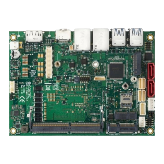
Page 18: Product Overview
— — Product Nomenclature and Function GMB-L3WHL200 Reference Manual 1. Product Overview connectors of the product are shown in the picture below. ◆ Top View - 18 -... -
Page 19: Jumper List
GMB-L3WHL200 Reference Manual 2. Jumper List For users to customize GMB-L3WHL200 features. In the following sections, short means covering a jumper cap over jumper pins; Open or N/C (not connected) means removing a jumper cap from jumper pins. Users can refer to below Top view picture and tables for jumper positions, functions, and signal description. -
Page 20: Flash Descriptor Security Override (Jp1)
— — Product Nomenclature and Function GMB-L3WHL200 Reference Manual Flash Descriptor Security Override (JP1) PIN No. Jumper Description 0= Enable security measures defined in the Flash 1-2, Open (Default) Descriptor. 2-3, Short 1= Disable Flash Descriptor Security (override) AT/ATX Mode Select (JP2) PIN No. -
Page 21: Led Bl- Power Selection (Jp3)
— — Product Nomenclature and Function GMB-L3WHL200 Reference Manual LED BL- Power Selection (JP3) PIN No. Jumper Description 1-2, Short (Default) Normal Operation 2-3, Short ROM Clear Contents LVDS_Panel- Power Selection (JP4) PIN No. Jumper Description 1-2, Short (Default) Normal Operation... -
Page 22: Rom Clear Select Jumper (Jbat2)
— — Product Nomenclature and Function GMB-L3WHL200 Reference Manual ROM Clear Select Jumper (JBAT2) JBAT2 JBAT2 PIN No. Jumper Description 1-2, Short (Default) Normal Operation 2-3, Short ROM Clear Contents - 22 -... -
Page 23: Connector List
— — Product Nomenclature and Function GMB-L3WHL200 Reference Manual 3.Connector List Connector Ref. label Ref. label Ref. label Ref. label SATA2 F_PANEL1 SO-DIMM1 HDMI1 SATA1 CPUFAN1 LAN2 COM1 SPI1 LAN1 COM2 MINI_CARD1 BATTERY1 USB3 COM3 M.2_1 USB1 COM4 AUDIO1 SATAPW1 M.2_2... - Page 24 — — Product Nomenclature and Function GMB-L3WHL200 Reference Manual Ref. Connector Function Display Port Connector HDMI1 HDMI connector LAN2 Giga LAN/ RJ45 Connector LAN1 Giga LAN/ RJ45 Connector USB3 USB 3.2 Gen2/ Type A connector USB1 USB 3.2 Gen2/ Type A connector AUDIO1 Audio(MIC+Line_in+Line_out )/ 2.0mm pitch HDR...
-
Page 25: Dc-In Power Connector (Cn5)
— — Product Nomenclature and Function GMB-L3WHL200 Reference Manual 1. DC-IN Power Connector (CN5) PIN No. Signal Description DC-IN 2. LVDS_Backlight PW Connector (CN2) PIN No. Signal Description LVDS_LCD_VDD BL_EN BKLT_PWM_CTR - 25 -... -
Page 26: Sata Power Connector (Satapw1)
— — Product Nomenclature and Function GMB-L3WHL200 Reference Manual 3. SATA Power Connector (SATAPW1) SATAPW 1 PIN No. Signal Description +5Vdc +5Vdc 4. CPU FAN Connector/ 4P ( CPUFAN1) CPU_FAN1 PIN No. Signal Description +12Vdc FAN_SPEED_OUT FAN_PWM - 26 -... -
Page 27: Front Panel Pin Hdr /8P (F_Panel1)
— — Product Nomenclature and Function GMB-L3WHL200 Reference Manual 5. Front Panel Pin HDR /8P (F_PANEL1) F_PANEL1 PIN No. Signal Description PIN No. Signal Description RST_SW PWRBTN# PWR LED (-) HDDLED(-) PWR LED (+) HDDLED(+) 6. Audio Pin HDR/ 8P (AUDIO1) AUDIO1 PIN No. -
Page 28: Usb2.0 Pin Hdr/ 10P (Usb2)
— — Product Nomenclature and Function GMB-L3WHL200 Reference Manual 7. USB2.0 Pin HDR/ 10P (USB2) USB2 PIN No. Signal Description PIN No. Signal Description USB D5 (+) USB D6 (+) USB D5 (-) USB D6 (-) 5V_USB (+) 5V_USB (+) -
Page 29: Debug Port, Lpc Interface Conn./ 9P (Cn3)
— — Product Nomenclature and Function GMB-L3WHL200 Reference Manual 8. Debug Port, LPC Interface Conn./ 9P (CN3) PIN No. Signal Description +3.3V DBG_PLTRST# LPC_FRAME# LPC_AD0 LPC_AD1 LPC_AD2 LPC_AD3 CLK_TPM_24M - 29 -... -
Page 30: Lvds Connector/ 40P (Cn4)
— — Product Nomenclature and Function GMB-L3WHL200 Reference Manual 9. LVDS Connector/ 40P (CN4) PIN No. Signal Description PIN No. Signal Description LVDS_PANEL_VCC LVDS_PANEL_VCC LVDS_PANEL_VCC LVDS_PANEL_VCC LVDS_DDC_CLK LVDS_VDD_EN LVDS_DDC_DATA LVDS_DET# LVDS_A_TXL+1 LVDS_A_TXL+0 LVDS_A_TXL-1 LVDS_A_TXL-0 LVDS_A_TXL+3 LVDS_A_TXL+2 LVDS_A_TXL-3 LVDS_A_TXL-2 LVDS_B_TXL+1 LVDS_B_TXL+0... -
Page 31: Gpio Pin Hdr/ 20P (Gpio1)
— — Product Nomenclature and Function GMB-L3WHL200 Reference Manual 10. GPIO Pin HDR/ 20P (GPIO1) GPIO1 PIN No. Signal Description PIN No. Signal Description +5VSB +5VSB DIO_16 DIO_15 DIO_14 DIO_13 DIO_12 DIO_11 DIO_10 DIO_9 DIO_8 DIO_7 DIO_6 DIO_5 DIO_4 DIO_3... -
Page 32: Spi Connector/ 9P (Spi1)
— — Product Nomenclature and Function GMB-L3WHL200 Reference Manual 11. SPI Connector/ 9P (SPI1) SPI1 Solder Side PIN No. Signal Description +3.3V_SPI SPIROM_SCK SPI_TPM_RST SPIROM_SI SPI_PIRQ SPIROM_SO SPIROM_CS0# - 32 -... -
Page 33: Serial Port Rs-232/422/485 /9P (Com1)
— — Product Nomenclature and Function GMB-L3WHL200 Reference Manual 12. Serial Port RS-232/422/485 /9P (COM1) Signal Description PIN No. RS 232 RS 422 RS 485 DCD 1 TX(-) TX(-) RX 1 TX(+) TX(+) TX 1 RX(+) RX(+) DTR 1 RX(-) -
Page 34: Serial Port Rs-232/ 9P (Com2~Com4)
— — Product Nomenclature and Function GMB-L3WHL200 Reference Manual 13. Serial Port RS-232/ 9P (COM2~COM4) PIN No. Signal Description DCD (n) RX (n) TX(n) DTR (n) DSR (n) RTS (n) CTS (n) RI (n) - 34 -... -
Page 35: Rtc Battery Connector (Battery1)
— — Product Nomenclature and Function GMB-L3WHL200 Reference Manual 14. RTC Battery Connector (BATTERY1) BATTERY1 PIN No. Signal Description +3V DC (+) GND (-) CAUTION The connector of RTC Battery has (+) and (-) polarities. ⚫ - 35 -... -
Page 36: Nano Sim Socket (Cn1)
— — Product Nomenclature and Function GMB-L3WHL200 Reference Manual 15. Nano SIM Socket (CN1) PIN No. Signal Description UIM_PWR UIM_RESET UIM_CLK UIM_VPP UIM_DATA CAUTION [ Figure-B ] [ Figure-A ] 1) Slide the socket lid (Unlock ) as Figure-A 2) Open the socket lid, place the card into the socket... -
Page 37: Spi Rom Programming Pin (Sata1,Sata2)
— — Product Nomenclature and Function GMB-L3WHL200 Reference Manual 16. SPI ROM Programming Pin (SATA1,SATA2) SATA1.SATA2 Two SATA 3.1 Gen2 (10 Gb/s)Port . 17. M.2 E Key Socket (M2_1) M2_1 M.2 / E Key H= 4.2mm 2230 Screw Size Thread Size :M3... -
Page 38: M Key Socket (M2_2)
— — Product Nomenclature and Function GMB-L3WHL200 Reference Manual 18. M.2 M Key Socket (M2_2) M2_2 H= 8.5mm Screw Size 2242/2280 Thread Size :M3 Total length: 3mm Thread length: 2mm Head diameter: 4mm M.2 M Key Socket (PCIe + SATA Signal) The board has one mechanical connector key M, accepting type 2280 of M.2 modules (H-8.5mm/... -
Page 39: Usb Connector (Usb1&Usb3)
— — Product Nomenclature and Function GMB-L3WHL200 Reference Manual 20. USB Connector (USB1&USB3) USB 1 USB 3 USB1,USB3 USB3.2 Gen2 Type A PIN No. Signal Description PIN No. Signal Description USB RX- USB RX+ USB D- USB D+ USB TX-... -
Page 40: Giga Lan Rj-45 Port (Lan1&Lan2)
— — Product Nomenclature and Function GMB-L3WHL200 Reference Manual 21. Giga LAN RJ-45 Port (LAN1&LAN2) LAN 1 LAN 2 RJ45 Connector RJ45 LEDs for display of network status: PIN No. Signal Description TX1+ TX1- TX2+ TX3+ TX3- TX2- TX4+ TX4-... -
Page 41: Hdmi Port (Hdmi1)
— — Product Nomenclature and Function GMB-L3WHL200 Reference Manual 22. HDMI Port (HDMI1) HDMI 1 PIN No. Signal Description PIN No. Signal Description HDMI1 DATA2(+) HDMI1 DATA2(-) HDMI1 DATA1(+) HDMI1 DATA1(-) HDMI1 DATA0(+) HDMI1 DATA0(-) HDMI1 CLK(+) HDMI1 CLK(-) HDMI1 DDC_SCL... -
Page 42: Display Port (Dp1)
— — Product Nomenclature and Function GMB-L3WHL200 Reference Manual Display Port (DP1) DP 1 PIN No. Signal Description PIN No. Signal Description ML_Lane 0(+) ML_Lane 0(-) ML_Lane 1(+) ML_Lane 1(-) ML_Lane 2(+) ML_Lane 2(-) ML_Lane 3(+) ML_Lane 3(-) AUX_CH(+) AUX_CH(-)... -
Page 43: Watch-Dog Timer
— — Product Nomenclature and Function GMB-L3WHL200 Reference Manual 24. Watch-Dog Timer The watchdog timer serves as a safeguard against possible system lock-up in your industrial computer system. In most industrial environments, there are heavy equipment, generators, high- voltage power lines, or power drops that have adverse effects on your computer system. For instance, when a power drop occurs, it could cause the CPU to come to a halt state or enter into an infinite loop, resulting in a system lock-up. - Page 44 — — Product Nomenclature and Function GMB-L3WHL200 Reference Manual Example programming The following example is written in Intel8086 assembly language. ;=============== ;<WDT Initial> ;=============== ;------------------------------------------- ;Enter the extended function mode ;------------------------------------------- MOV DX,2EH MOV AL,87H OUT DX,AL OUT DX,AL ;---------------------------------------------- ;Select logical device WDT(number 8)
- Page 45 — — Product Nomenclature and Function GMB-L3WHL200 Reference Manual MOV AL,00H OUT DX,AL ;------------------------------------------ ;Exit the extended function mode ;------------------------------------------ MOV DX,2EH MOV AL,AAH OUT DX,AL ;=============================== ;<WDT START: counter set and a start> ;=============================== ;--------------------------------------------- ;Enter the extended function mode ;---------------------------------------------...
- Page 46 — — Product Nomenclature and Function GMB-L3WHL200 Reference Manual ;---------------------------------------------------------------------------------- OUT DX,AL ;--------------------------------------- ;Exit the extended function mode ;--------------------------------------- MOV DX,2EH MOV AL,AAH OUT DX,AL ;============== ;<WDT STOP> ;============== ;----------------------------------------- ;Enter the extended function mode ;----------------------------------------- MOV DX,2EH MOV AL,87H...
- Page 47 — — Product Nomenclature and Function GMB-L3WHL200 Reference Manual ;----------------------------------- OUT DX,AL ;----------------------------------- ;Exit the extended function mode ;----------------------------------- MOV DX,2EH MOV AL,AAH OUT DX,AL CAUTION The timer’s intervals have a tolerance of ± 2 seconds. ⚫ - 47 -...
-
Page 48: Bios Setup
BIOS Setup This section describes AMI’s Setup program built into the FLASH ROM BIOS. - 48 -... -
Page 49: Introduction
— — BIOS Setup GMB-L3WHL200 Reference Manual 1. Introduction The BIOS setup program allows users to modify the basic system configuration. In this following chapter will describe how to access the BIOS setup program and the configuration options that may be changed. -
Page 50: Using Setup
— — BIOS Setup GMB-L3WHL200 Reference Manual 2. Using Setup In general, you use the arrow keys to highlight items, press <Enter> to select, use the PageUp and PageDown keys to change entries, press <F1> for help and press <Esc> to quit. The following table provides more detail about how to navigate in the Setup program using the keyboard. -
Page 51: Main Menu
— — BIOS Setup GMB-L3WHL200 Reference Manual 2. Main Menu Once you enter the Aptio Setup Utility, the Main Menu will appear on the screen. The Main Menu allows you to select from several setup functions and exit choices. Use the arrow keys to select among the items and press <Enter>... -
Page 52: Setup Items
— — BIOS Setup GMB-L3WHL200 Reference Manual 1. Setup Items The selectable tabs are as follows. Main Record some basic hardware configurations in your computer and set the system clock. Advanced configure your CPU and other system devices for basic operation through the following sub-menus. -
Page 53: Main
— — BIOS Setup GMB-L3WHL200 Reference Manual 3. Main View the basic system structure. The following items are displayed. Indication item of the main menu Item Indication Example Explanation Project Name GMB-L3WHL200 Displays the BIOS name. Project Version BIOS REV. 1.00 Displays the BIOS version. -
Page 54: Advanced
— — BIOS Setup GMB-L3WHL200 Reference Manual 4. Advanced This section allows you to configure your CPU and other system devices for basic operation through the following sub-menus. - 54 -... -
Page 55: Cpu Configuration
— — BIOS Setup GMB-L3WHL200 Reference Manual 1. CPU Configuration CPU Configuration Item Options Description When enabled, a VMM can utilize the Intel (VMX) Virtualization Disabled additional hardware capabilities Technology Enabled provided by vanderpool technology. Number of cores to enable in each... -
Page 56: Pch-Fw Configuration
— — BIOS Setup GMB-L3WHL200 Reference Manual 2. PCH-FW Configuration PCH-FW Configuration Item Options Description Disabled When Disabled ME will be put into ME ME State Enabled temporarily disabled mode. Enable/ Disable Intel® manageability features. Disabled This option disables/ enables manageability... -
Page 57: Trusted Computing
— — BIOS Setup GMB-L3WHL200 Reference Manual 3. Trusted Computing Trusted Computing Item Options Description Enables or Disables BIOS support for security device. Disable Security Device Support O.S. will not show Security Device. TCG EFI protocol Enable and INT1A interface will not be available. -
Page 58: Acpi Settings
— — BIOS Setup GMB-L3WHL200 Reference Manual ACPI Settings ACPI Settings Item Options Description Disabled Enable ACPI Auto Configuration Do not change this setting. Enabled Enables or Disables System ability to Hibernate Disabled Enable Hibernation (OS/S4 Sleep State). This option may not be Enabled effective with some operating systems. -
Page 59: Super Io Configuration
— — BIOS Setup GMB-L3WHL200 Reference Manual 5. Super IO Configuration Super IO Configuration Item Options Description Serial Port 1 Configuration Refer to Serial Port 1 Serial Port 2 Configuration Refer to Serial Port 2 Serial Port 3 Configuration Refer to Serial Port 3... - Page 60 — — BIOS Setup GMB-L3WHL200 Reference Manual Serial Port 2 Configuration Item Options Description Disabled Serial Port Enable or Disable Serial Port (COM). Enabled Serial Port 3 Configuration Item Options Description Disabled Serial Port Enable or Disable Serial Port (COM).
-
Page 61: H/W Monitor
— — BIOS Setup GMB-L3WHL200 Reference Manual 6. H/W Monitor View hardware monitor information such as the CPU temperature. - 61 -... -
Page 62: Usb Configuration
— — BIOS Setup GMB-L3WHL200 Reference Manual 7. USB Configuration USB Configuration Item Options Description Enable Legacy USB support. Enabled Auto option disables legacy support if no USB Legacy USB Support Disabled devices are connected. Disable option will keep USB devices available only for EFI Auto applications. - Page 63 — — BIOS Setup GMB-L3WHL200 Reference Manual 8. NVMe Configuration USB Configuration Item Options Description Select either Short or Extended Self Test. Short Short option will take couple of minutes and Self Test Option extended option will take several minutes to...
-
Page 64: Chipset
— — BIOS Setup GMB-L3WHL200 Reference Manual 5. Chipset 1. System Agent (SA) Configuration System Agent (SA) Configuration Graphic Configuration Item Options Description Auto Select which of IGFX/PEG/PCI graphic IGFX Primary Display device should be primary display or select SG for switchable Gfx. - Page 65 — — BIOS Setup GMB-L3WHL200 Reference Manual Item Options Description Select DVMT5.0 pre-allocated (Fixed) DVMT Pre-Allocated graphic memory size used by the internal graphic device. 32M/F7 128M Select DVMT5.0 total graphic memory DVMT Total Gfx Mem 256M size used by the internal graphic device.
-
Page 66: Pch-Io Configuration
— — BIOS Setup GMB-L3WHL200 Reference Manual 2. PCH-IO Configuration PCH-IO Configuration Item Options Description Enabled Onboard LAN A Controller Enable/ Disable onboard NIC Disabled Enabled Onboard LAN B Controller Enable/ Disable onboard NIC Disabled Enabled Wake on LAN Enable/ Disable integrated LAN to wake the system... - Page 67 — — BIOS Setup GMB-L3WHL200 Reference Manual SATA and RST Configuration Item Options Description Enabled SATA Controller(s) Enable/ Disable SATA Device Disabled SATA Mode Selection AHCI Determines how SATA controllers operate HD Audio Configuration Item Options Description Control Detection of the HD-Audio device.
-
Page 68: Security
— — BIOS Setup GMB-L3WHL200 Reference Manual 6. Security Secure Boot Item Options Description Secure Boot feature is Active if Secure Boot is Enabled, Enabled Secure Boot Platform Key(PK) is enrolled and the System is in Disabled User mode. The mode change requires platform reset Secure Boot mode options: Standard or Custom. -
Page 69: Boot
— — BIOS Setup GMB-L3WHL200 Reference Manual 7.Boot Boot Item Options Description Number of seconds to wait for setup Setup Prompt Timeout activation key. 65535(0xFFFF) means indefinite waiting. Bootup NumLock State Select the keyboard Numlock state Enabled Quiet Boot Enables or disables quite boot option... -
Page 70: Save And Exit
— — BIOS Setup GMB-L3WHL200 Reference Manual 7.Save and Exit Save Changes and Reset Reset the system after saving the changes. Discard Changes and Reset Any changes made to BIOS settings during this session of the BIOS setup program are discarded. -
Page 71: Appendix
Appendix This section lists the specifications and components suggestion, block diagram, driver installation, and mechanical drawing. - 71 -... -
Page 72: System Reference
— — Appendix GMB-L3WHL200 Reference Manual 1. System Reference 1. Specifications Model Name GMB-L3WHL200 8th Intel® Embedded Whiskey Lake-U Core™ i3-8145UE Chipset SoC (System on chipset) BIOS AMI UEFI BIOS Operation System Windows®10 IoT Enterprise LTSC 2019 64 bit System Memory... -
Page 73: Block Diagram
— — Appendix GMB-L3WHL200 Reference Manual 2. Block Diagram - 73 -... -
Page 74: Dimension
— — Appendix GMB-L3WHL200 Reference Manual 3. Dimension - 74 -... -
Page 75: Installation
— — Appendix GMB-L3WHL200 Reference Manual 4. Installation 1. Mainboard Installation Some components are very close to the mounting holes. Please take precautionary measure to avoid damaging these components when installing the motherboard. 2. Memory Installation The DDR4 memory sockets are divided into A and B two channels, each has two sockets showed as below. - Page 76 — — Appendix GMB-L3WHL200 Reference Manual 3. Mini PCIe Card Installation Use M2x5 screw to fix mini PCIe card. 2) Check if the mini PCIe card is loose. - 76 -...
- Page 77 — — Appendix GMB-L3WHL200 Reference Manual 4. M.2 M Key Card Installation (For 2280 Card) 1) Use 5mm socket screwdriver to fix M3x6.5 standoff first. 2) Use M3x6 screw to fix M.2 card. 3) Check if the M.2 card is loose.
- Page 78 — — Appendix GMB-L3WHL200 Reference Manual 5. M.2 M Key Card Installation (For 2242 Card) 1) Use 5mm socket screwdriver to fix M3x6.5 standoff first. 2) Use M3x6 screw to fix M.2 card. 3) Check if the M.2 card is loose.
- Page 79 — — Appendix GMB-L3WHL200 Reference Manual 6. M.2 E Key Card Installation 1) Use M3x6 screw to fix M.2 card. 2) Check if the M.2 card is loose. - 79 -...
- Page 80 — — Appendix GMB-L3WHL200 Reference Manual 7. HDMI Installation 1) Use M3x8 screw to fix HDMI and I/O panel. - 80 -...
-
Page 81: List Of Optional Products
List of Optional Products This section lists optional items that can be used along with the product. - 81 -... -
Page 82: Optional Product
SATA Power Cable LYYY341 SATA Cable LYYY271 Work with storage kit Audio Cable LYYY261 Mainboard DC IN Cable LYYY251 COM Port Cable LYYY281 GPIO Cable 16bit LYYY291 Visit the CONTEC website for the latest optional products. https://www.contec.com/ Download - 82 -... - Page 83 Customer Support and Inquiry CONTEC provides the following support services for you to use CONTEC products more efficiently and comfortably. - 83 -...
- Page 84 — — Customer Support and Inquiry GMB-L3WHL200 Reference Manual 1. Services CONTEC offers the useful information including product manuals that can be downloaded through the CONTEC website. Download https://www.contec.com/download/ You can download updated driver software, firmware, and differential manuals in several languages. Membership registration (myCONTEC) is required to use the services.
- Page 85 No part of this document may be copied or reproduced in any form by any means without ⚫ prior written consent of CONTEC CO., LTD. CONTEC CO., LTD. makes no commitment to update or keep current the information contained ⚫ in this document.
- Page 86 CONTEC CO., LTD. 3-9-31, Himesato, Nishiyodogawa-ku, Osaka 555-0025, Japan https://www.contec.com/ No part of this document may be copied or reproduced in any form by any means without prior written consent of CONTEC CO., LTD. GMB-L3WHL200 Reference Manual NA07904 (LYZC011) [02032021]...