Table of Contents
Advertisement
Available languages
Available languages
Advertisement
Chapters
Table of Contents

Related Manuals for HAMPTON BAY AG524-ORB


Summary of Contents for HAMPTON BAY AG524-ORB
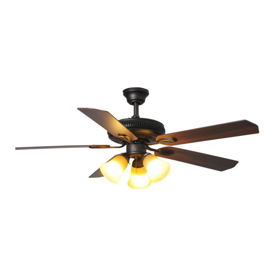
- Page 1 Item #xxx-xxx Model # AG524-ORB USE AND CARE GUIDE GLENDALE 52 INCH CEILING FAN Questions, problems, missing parts? Before returning to the store call Hampton Bay Customer Service 8 a.m. - 6 p.m., EST, Monday-Friday 1-877-527-0313 HAMPTONBAY.COM THANK YOU THANK YOU...
-
Page 2: Table Of Contents
Table of Contents Table of Contents ............Operation ..............Pull Chain Operating Instructions .......... Safety Information ............Reverse Switch Operating Instructions ........Warranty ................. Care and Cleaning ............Pre-Installation .............. Troubleshooting ............Tools Required ................. Service Parts ............... Hardware Included ..............Package Contentd .............. -
Page 3: Safety Information
Safety Information To reduce the risk of electric shock, ensure electricity has WARNING: To reduce the risk of electric shock, ensure been turned off at the circuit breaker or fuse box before electricity has been turned off at the circuit breaker or fuse beginning. -
Page 4: Warranty
Warranty We warrant the fan motor to be free from defects in workmanship and material present at time of shipment from the factory for a period of lifetime after the date of purchase by the original purchaser. We also warrant that all other fan parts, excluding any glass or acrylic blades, to be free from defects in workmanship and material at the time of shipment from the factory for a period of one year after the date of purchase by the original purchaser. -
Page 5: Hardware Included
Pre-Installation (continued) HARDWARE INCLUDED HARDWARE INCLUDED NOTE: Hardware shown to actual size unless noted otherwise in the table below. Part Part Description Description Quantity Quantity Blade attachment hardware Mounting hardware Plastic wire nut Light holder thumbscrews (preassembled) Balance kit (not to scale) Mounting bracket hardware (preassembled) Clevis pin (preassembled) Cotter pin (preassembled) -
Page 6: Package Contentd
Pre-Installation (continued) PACKAGE CONTENTS PACKAGE CONTENTS Part Part Description Description Quantity Quantity Part Part Description Description Quantity Quantity Mounting bracket (preassembled) Fan motor assembly Canopy ring Blades Canopy Blade arms Canopy bottom cover Light kit Hanger ball/downrod assembly Glass shades Coupling cover... -
Page 7: Dual Mounting Instruction
Pre-Installation (continued) DUAL MOUNTING INSTRUCTIONS DUAL MOUNTING INSTRUCTIONS This ceiling fan is supplied with two types of hanging assemblies: the standard ceiling installation using the downrod with ball and socket mounting, and the "close-to-ceiling" mounting. The "close-to-ceiling" mounting is recommended in rooms with less than 8-foot ceilings or in areas where additional space is desired from the floor to the fan blades. -
Page 8: Installation
Installation MOUNTING OPTIONS MOUNTING OPTIONS WARNING: To reduce the risk of fire, electric shock, or NOTE: You may need a longer downrod to maintain proper personal injury, mount the fan to an outlet box marked blade clearance when installing on a steep, sloped ceiling. acceptable for fan support using the screws provided with the The maximum angle allowable is 18°... -
Page 9: Assembly
Assembly — Standard Ceiling Mounting Preparing the canopy Preparing the motor Remove the clevis pin (GG), and cotter pin (HH), and Remove the canopy ring (B) from the canopy (C). loosen the two collar setscrews (II) from the motor collar. Remove the two non-slotted screws (FF) from the canopy (C), and loosen the slotted screws (FF) on the canopy (C). - Page 10 Assembly — Close-to-Ceiling Mounting Preparing the canopy Preparing the motor Remove three of the six collar mounting screws with Remove the canopy ring (B) from the canopy (C). lock washers (JJ) (every other one) from the collar on Remove the two non-slotted screws (FF) from the top of the fan motor assembly (G).
- Page 11 Assembly — Hanging the Fan Attaching the fan to the electrical box WARNING: To reduce the risk of fire, electric shock or other personal injury, mount the fan only to an outlet box or supporting system marked acceptable for fan support and use the mounting screws provided with the outlet box.
- Page 12 Assembly — Hanging the Fan (continued) Installing the safety cable Secure the safety cable (SS) to the building structure using a wood screw (not included). Making the electrical WARNING: Check to see that all connections are tight, including ground, and that no bare wire is visible at the wire connections nuts (except for the ground wire).
-
Page 13: Standard Ceiling Mounting
Assembly — Hanging the Fan (continued) Standard ceiling mounting Close-to-ceiling mounting WARNING: Locking slots of the canopy (C) are provided WARNING: Make sure the tab on the mounting bracket (A) only as an aid to mounting. Do not leave the fan assembly properly sits in the groove in the hanger ball (E) before unattended until all four canopy screws are engaged and attaching the canopy (C) to the mounting bracket (A) by... -
Page 14: Attaching The Fan Blades
Assembly — Attaching the Fan Blades Removing the rubber Attaching the blades to the packing mounts blade arms The fan motor assembly (G) is shipped with rubber Attach the blades (H) to the blade arms (I) using the three screws with fiber washers provided with the packing mounts (XX) to prevent movement during blade attachment hardware (AA). -
Page 15: Installing The Light Kit
Assembly — Installing the Light Kit Making the polarized plug Mounting the glass shades and connections installing the light bulbs Mount the glass shades (K) to the light sockets by CAUTION: Before starting the installation, disconnect the partially unscrewing the three thumbscrews (DD) on power by turning off the circuit breaker or removing the fuse each glass holder, inserting the glass shades (K), and at the fuse box. -
Page 16: Operation
Operation PULL CHAIN OPERATING INSTRUCTIONS PULL CHAIN OPERATING INSTRUCTIONS Install two pull chains and fobs (MM) onto the pull chains located in the switch housing and light kit (J). Turn on the power and check the operation of the fan. The pull chain controls the fan speed as follows: 1 pull - High, 2 pulls - Medium, 3 pulls - Low, and 4 pulls - Off. -
Page 17: Care And Cleaning
Care and Cleaning Do not Do not Check the support connections, brackets, and blade Do not use water when cleaning. Water could damage the attachments twice a year. Make sure they are secure. motor, or the wood, or possibly cause an electrical shock. Because of the fan’s natural movement, some connections may become loose over time. - Page 18 Troubleshooting (continued) Problem Problem Solution Solution This unit is equipped with a wattage limiting device. Lamping in excess of 190 watts will disable your Lights shut off and will ceiling fan's light kit. To reset your light kit, you must turn the power off and relamp, keeping the not come back on.
-
Page 19: Service Parts
Service Parts Part Part Description Description Part Part Description Description Mounting bracket (preassembled) Blade attachment hardware Canopy ring Mounting hardware Canopy Plastic wire nut Canopy bottom cover Light holder thumbscrews (preassembled) Hanger ball/downrod assembly Balance kit Coupling cover Mounting bracket hardware (preassembled) Fan motor assembly Clevis pin (preassembled) 5 blades... - Page 20 Questions, problems, missing parts? Before returning to the store, call Hampton Bay Customer Service 8 a.m. - 6 p.m., EST, Monday-Friday 1-877-527-0313 HAMPTONBAY.COM Retain this manual for future use. AG524000001-C PTS-207168-071612 PTS-208138-081312...
- Page 21 MERCI Nous vous remercions d'avoir fait confiance a Hampton Bay en achetant ce ventilateur de plafond. Nous nous efforcons en permanence de creer des produits de qualite concus pour perfectionner votre maison. Vous pouvez visiter notre site en ligne pour consulter notre gamme complete de produits pour vos besoins de renovation residentielle.
- Page 22 Table des matières Table des matières ............Utilisation ..............Consignes d'utilisation de la chaîne (tirette) ......Consignes de sécurité........... Consignes d'utilisation de l'interrupteur d'inversion ....Garantie ................Entretien et nettoyage ..........Pré-installation .............. Dépannage ..............Caractéristiques ............... Outils requis ................Pièces de rechange .............
-
Page 23: Consignes De Sécurité
Consignes de sécurité Pour réduire les risques d’électrocution, assurez-vous que le AVERTISSEMENT : Pour réduire les risques courant est coupé au niveau des disjoncteurs ou de la boîte d’électrocution, assurez-vous que le courant est coupé au de fusibles avant de procéder a l'installation. niveau des disjoncteurs ou de la boîte de fusibles avant de procéder a l'installation. -
Page 24: Garantie
Garantie Nous garantissons que le moteur du ventilateur est exempt de tout défaut de fabrication et de main-d'œuvre au moment de son expédition de l'usine et ce, pour toute sa durée de vie à compter de la date d'achat par l'acheteur original. Nous garantissons également que toutes les autres pièces du ventilateur, en excluant les pales de verre ou de résine acrylique, sont exemptes de tout défaut de fabrication ou de matériaux au moment de leur expédition de l’usine, et ce, pendant une période d'un an suivant la date d’achat par l’acheteur original. -
Page 25: Quincaillerie Comprise
Pré-installation (suite) QUINCAILLERIE COMPRISE QUINCAILLERIE COMPRISE REMARQUE : Quincaillerie illustrée à la grandeur nature sauf indication contraire dans le tableau ci-dessous. Pièce Pièce Description Description Quantité Quantité Quincaillerie de fixation des pales Quincaillerie de montage Capuchon de connexion en plastique Vis à... -
Page 26: Contenu De L'emballage
Pré-installation (suite) CONTENU DE L’EMBALLAGE CONTENU DE L’EMBALLAGE Pièc Pièc Description Description Quantité Quantité Pièc Pièc Description Description Quantité Quantité Support de fixation (pré-assemblé) Moteur du ventilateur Anneau de coupelle Pales Coupelle Supports de pale Couvercle inférieur de coupelle Luminaire Boule et tige de suspension Abat-jour en verre Couvercle de raccordement... -
Page 27: Doubles Instructions De Montage
Pré-installation (suite) DOUBLES INSTRUCTIONS DE MONTAGE DOUBLES INSTRUCTIONS DE MONTAGE Ce ventilateur de plafond est livré avec deux options d'installation : une tige et une boule de suspension pour une installation normale et le nécessaire pour une installation près du plafond. L’installation près du plafond est recommandée pour les pièces dont le plafond est à... -
Page 28: Installation
Installation OPTIONS D'INSTALLATION OPTIONS D'INSTALLATION AVERTISSEMENT : Pour réduire les risques d'incendie, de REMARQUE : Une tige de suspension plus longue peut choc électrique ou de blessure, fixez le ventilateur à une boîte s'avérer nécessaire pour maintenir une distance correcte de sortie de courant portant la mention capable de supporter entre les pales et le plafond dans le cas d'une installation sur un ventilateur, au moyen des vis fournies avec la boîte de... - Page 29 Assemblage – Installation normale Préparation de la coupelle Préparation du moteur Retirez l'axe d'assemblage (GG) et la goupille fendue Retirez l’anneau de coupelle (B) de la coupelle (C). (HH), et desserrez les deux vis de pression du collet (II) sur le collet du moteur. Retirez complètement les vis sans empreinte fendue (FF) de la coupelle (C) et desserrez les vis à...
- Page 30 Assemblage — Installation près du plafond Préparation de la coupelle Préparation du moteur Retirez trois des six vis de montage du collet avec Retirez l’anneau de coupelle (B) de la coupelle (C). rondelles de blocage (JJ) (en retirer une sur deux) qui Retirez complètement les vis sans empreinte fendue (FF) fixent le collet du moteur au dessus du moteur du de la coupelle (C) et desserrez les vis à...
- Page 31 Assemblage – Suspension du ventilateur Montage du ventilateur sur la boîte électrique Serrez bien les deux vis de montage. AVERTISSEMENT : Pour réduire les risques d’incendie, de choc électrique ou de toute autre blessure. Fixez le ventilateur à une boîte de sortie de courant ou un système de support portant la mention capable de supporter un ventilateur au moyen des vis fournies avec la boîte de sortie Faites passer les fils d’alimentation de 120 volts par...
-
Page 32: Assemblage
Assemblage – Suspension du ventilateur (suite) Installation du câble de sécurité Fixez solidement le câble de sécurité (SS) à la structure du bâtiment à l'aide d'une vis à bois (non inclus) Effectuer les connexions AVERTISSEMENT : Veillez à ce que toutes les connexions soient bien serrées, y compris les fils de mise à... -
Page 33: Installation Normale
Assemblage – Suspension du ventilateur (suite) Installation normale Installation près du plafond AVERTISSEMENT : Les fentes de blocage de la coupelle AVERTISSEMENT : Assurez-vous que la languette du (C) sont uniquement fournies pour faciliter l'installation. Ne support de fixation (A) repose correctement dans le sillon de laissez pas le ventilateur sans surveillance tant que les quatre la boule de suspension (E) avant de fixer la coupelle (C) sur le vis de la coupelle ne sont pas toutes en place et bien serrées. -
Page 34: Installation Des Pales Du Ventilateur
Assemblage – Installation des pales du ventilateur Retirez les cinq attaches Installation des pales sur les d'emballage en caoutchouc supports de pales Le moteur du ventilateur (G) est expédié avec des Fixez les pales (H) sur les supports de pale (I) au moyen des trois vis avec rondelles en fibre fournies attaches d'emballage en caoutchouc (XX) pour avec la quincaillerie de fixation des pales (AA). -
Page 35: Installation Du Luminaire
Assemblage - Installation du luminaire Effectuer les branchements de Installation des abat-jour en verre prise polarisée et des ampoules Installez les abat-jour en verre (K) dans les douilles ATTENTION : Avant de commencer l'installation, en desserrant à moitié les trois vis à oreilles (DD) sur débranchez l'alimentation électrique en fermant le disjoncteur chaque support d'abat-jour, puis en insérant les ou en retirant le fusible approprié... -
Page 36: Utilisation
Utilisation CONSIGNES D'UTILISATION DE LA CHAÎNE CONSIGNES D'UTILISATION DE LA CHAÎNE (TIRETTE) (TIRETTE) Installez deux chaînes (tirettes) et breloques (MM) sur les chaînes situées dans le boîtier d'interrupteur et le luminaire (J). Mettez le ventilateur en marche et vérifiez son fonctionnement. La chaîne (tirette) du ventilateur permet de contrôler sa vitesse comme suit : Tirer une fois pour la vitesse élevée, deux fois pour la vitesse... -
Page 37: Entretien Et Nettoyage
Entretien et nettoyage À faire À faire À ne pas faire À ne pas faire Vérifiez les raccords de support, les brides et les fixations N'appliquez pas d'huile sur le ventilateur ou le moteur. Le des pales deux fois par an. Vérifiez qu’ils sont solidement moteur est doté... - Page 38 Dépannage (suite) Problème Problème Solution Solution Cet appareil est doté d'un dispositif de limitation de puissance. Des ampoules de plus de 190 W Le luminaire s'éteint neutraliseront votre luminaire de ventilateur de plafond. Pour remettre le luminaire en marche, couper et ne se rallume pas.
-
Page 39: Pièces De Rechange
Pièces de rechange Pièc Pièc Description Description Pièc Pièc Description Description Support de fixation (pré-assemblé) Quincaillerie de fixation des pales Anneau de coupelle Quincaillerie de montage Coupelle Capuchon de connexion en plastique Couvercle inférieur de coupelle Vis à oreilles pour support de luminaire (pré-assemblées) Boule et tige de suspension Nécessaire d'équilibrage Couvercle de raccordement... - Page 40 Avant de retourner au magasin, appelez le service à la clientèle Hampton Bay entre 8 h et 18 h (HNE) du lundi au vendredi au 1-877-527-0313 HAMPTONBAY.COM Conservez ce guide pour un usage ultérieur. AG524000001-C PTS-207168-071612...