Table of Contents
Advertisement
Available languages
Available languages
Item # 904-384
Model # 68168
UL Model # 68-ATR
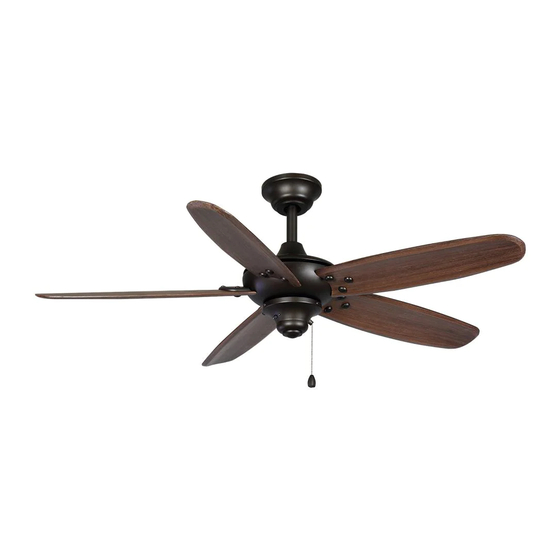
USE AND CARE GUIDE
ALTURA 68-INCH CEILING FAN
Questions, problems, missing parts? Before returning to the store call
Hampton Bay Customer Service
8 a.m. - 6 p.m., EST, Monday-Friday.
1-877-527-0313
HAMPTONBAY.COM
THANK YOU
We appreciate the trust and confidence you have placed in Hampton Bay through the purchase of this ceiling fan. We strive to continually create
quality products designed to enhance your home. Visit us online to see our full line of products available for your home improvement needs.
Thank you for choosing Hampton Bay!
Advertisement
Chapters
Table of Contents

Related Manuals for HAMPTON BAY ALTURA


Summary of Contents for HAMPTON BAY ALTURA
- Page 1 THANK YOU We appreciate the trust and confidence you have placed in Hampton Bay through the purchase of this ceiling fan. We strive to continually create quality products designed to enhance your home. Visit us online to see our full line of products available for your home improvement needs.
-
Page 2: Table Of Contents
Table of Contents Table of Contents ............2 Assembly ............... 7 Safety Information ............2 Operation ..............12 Warranty ................. 3 Care and Cleaning ............13 Pre-Installation .............. 3 Troubleshooting ............14 Installation ..............6 Safety Information To reduce the risk of electric shock, ensure the WARNING: To reduce the risk of personal injury, electricity has been turned off at the circuit breaker or do not bend the blade brackets (also referred to as... -
Page 3: Warranty
A certain amount of “wobble” is normal and should not be considered a defect. Servicing performed by unauthorized persons shall render the warranty invalid. There is no other express warranty. Hampton Bay hereby disclaims any and all warranties, including but not limited to those of merchantability and tness for a particular purpose to the extent permitted by law. - Page 4 Pre-Installation (continued) HARDWARE INCLUDED NOTE: Hardware not shown to actual size. Part Description Quantity Part Description Quantity Blade attachment hardware Balancing kit Plastic wire connector Decorative nut Hanger pin Locking pin...
-
Page 5: Package Contents
Pre-Installation (continued) PACKAGE CONTENTS Part Description Quantity Part Description Quantity Slide-on mounting bracket Decorative motor collar cover (inside the canopy) Blade Ball/downrod assembly Switch cup adaptor Canopy with canopy ring Remote control (battery included) attached Fan-motor assembly Switch cup (receiver included) IMPORTANT: This product and/or components are governed by one or more of the following U.S. -
Page 6: Installation
Installation MOUNTING OPTIONS WARNING: To reduce the risk of re, electric shock, or NOTE: You may need a longer downrod to maintain proper personal injury, mount the fan to an outlet box marked blade clearance when installing on a steep, sloped ceiling. acceptable for fan support using the screws provided with the The maximum angle allowable is 30°... - Page 7 Assembly – Standard Ceiling Mounting Preparing for mounting Routing the wires Remove the canopy ring from the canopy (C) by turning the Route the wires exiting the top of the fan motor (D) into the ring to the right until it unlocks. decorative motor collar cover (F) and through the canopy ring (C).
-
Page 8: Hanging The Fan
Assembly – Hanging the Fan Attaching the fan to the electrical Hanging the fan Carefully lift the fan-motor assembly (D) up to the WARNING: T mounting bracket (A). other personal injury, mount the fan to an outlet box or supporting system marked acceptable for fan support and Seat the hanger ball portion of the ball/downrod assembly use the mounting screws provided with the outlet box. -
Page 9: Assembly
Assembly – Hanging the Fan (continued) Making the electrical connection Mounting the fan IMPORTANT: Use the wire connecting nuts supplied with WARNING: When using the standard ball/downrod your fan. Secure the connectors with electrical tape, and mounting, the tab in the ring at the bottom of the mounting ensure there are no loose strands or connections. -
Page 10: Attaching The Fan Blades
Assembly – Attaching the Fan Blades Attaching the fan blades Attach the blade (G) to the blade bracket using the decorative nuts (FF) and the blade attachment screws (AA) as shown. Start a blade attachment screw (AA) into the decorative nut (FF). Repeat for the two remaining decorative nuts and blade attachment screws. -
Page 11: Attaching The Switch Cup
Assembly – Attaching the Accessories Attaching the switch cup adaptor Attaching the switch cup Remove one screw from the black bracket below the fan CAUTION: To reduce the risk of electric shock, disconnect motor assembly (D). Loosen, but do not remove the other the electrical supply circuit to the fan before installing the two screws. -
Page 12: Operation
Operation Remote Control - Your fan is equipped with a remote control to operate the speed and lights of your new ceiling fan. For more information on how to install the remote control, see the remote ON DIP control instruction packaged with the remote control components. The appropriate speed setting for warm or cool weather depends on factors such as the room size, ceiling height, and number of fans. -
Page 13: Care And Cleaning
Operation (continued) Operating the fan Light button = Press and release the button immediately to turn on or turn off the light. Press and hold the button to dim or brighten the light to the desired level and then release. (For tungsten only and down light function, turn the switch to "DIM".) Low button = Low speed Medium button = Medium speed... -
Page 14: Troubleshooting
Troubleshooting Problem Solution The fan will not start Check the main and branch circuit fuses or breakers. Check the line wire connections to the fan and switch wire connections in the switch housing. Check the battery in the remote control. Ensure you are in the normal range of 10-20 feet. - Page 15 This page intentionally left blank.
- Page 16 Questions, problems, missing parts? Before returning to the store call Hampton Bay Customer Service 8 a.m. - 6 p.m., EST, Monday-Friday. 1-877-527-0313 HAMPTONBAY.COM Retain this manual for future use. X0000000000-A...
- Page 17 GRACIAS POR TU COMPRA Apreciamos la confianza que has depositado en Hampton Bay al comprar este ventilador de techo. Nos esforzamos para continuamente crear productos de calidad diseñados para tu hogar. Visítanos en Internet para ver nuestra línea completa de productos disponibles para las...
- Page 18 Tabla de Contenido Tabla de Contenido ............2 Ensamblaje ..............7 Información de Seguridad ..........2 Funcionamiento ............12 Garantía ................3 Mantenimiento y Limpieza......... 13 Pre-Instalación .............. 3 Solución de problemas ..........14 Instalación ..............6 Información de Seguridad Para disminuir el riesgo de descarga eléctrica, asegúrate de que ADVERTENCIA: Para reducir el riesgo de lesiones la electricidad ha sido apagada en el cortacircuitos o la caja de...
-
Page 19: Garantía
Es normal cierta “oscilación” y no se considerará una falla. Cualquier servicio técnico conducido por personas no autorizadas anulará la garantía. No hay ninguna otra garantía expresa. Mediante la presente Hampton Bay se exime de cualquier garantía, incluyendo pero sin limitarse a aquellas de comercialización e idoneidad para un n particular, de acuerdo a lo contemplado por la ley. La duración de cualquier garantía implícita que no se pueda eximir está... - Page 20 Pre-Instalación (continuación) HERRAJES INCLUIDOS NOTA: No se muestra el tamaño real de los herrajes. Pieza Descripción Cantidad Pieza Descripción Cantidad Herrajes para montaje de las aspas Kit de compensación de aspas Conector plástico para cable Tuerca decorativa Pasador de soporte Pasador de cierre...
- Page 21 Pre-Instalación (continuación) CONTENIDO DEL PAQUETE Pieza Descripción Cantidad Pieza Descripción Cantidad Soporte deslizante de montaje Cubierta decorativa del (dentro de la cubierta) collarín del motor Aspa Ensamblado de tubo bajante/bola Adaptador de la caja del interruptor Cubierta con aro incorporado Control remoto (batería incluida) Ensamblaje del motor del ventilador Caja del interruptor...
-
Page 22: Instalación
NOTA: Tal vez necesites un tubo bajante más largo para descarga eléctrica o lesiones personales, instala el ventilador mantener la altura mínima adecuada de las aspas, al instalar en una caja eléctrica marcada como “aprobada como soporte el ventilador en un techo inclinado. El ángulo máximo de ventilador”... - Page 23 Ensamblaje — Montaje Estándar en Techo Preparar para el montaje Disposición de los cables Retira el aro de la cubierta (C), girándolo hacia la derecha Inserta los cables que salen por la parte superior del motor hasta soltarlo. del ventilador (D) en la cubierta decorativa del collarín del motor (F) y a través del aro de la cubierta (C).
- Page 24 Ensamblado — Colgar el Ventilador Instalar el ventilador en la caja Colgar el ventilador eléctrica Con cuidado alza el ensamblado del motor del ventilador ADVERTENCIA: Para reducir el riesgo de incendio, (D) hasta el soporte de montaje (A). descarga eléctrica o lesiones físicas, sólo instala el ventilador en una caja eléctrica o sistema de soporte aprobados para Coloca la bola de soporte del ensamblado de tubo bajante/ ventiladores y usa los tornillos de montaje que vienen con la...
-
Page 25: Ensamblaje
Ensamblaje — Colgar el Ventilador (continuación) Cómo hacer las conexiones Cómo montar el ventilador eléctricas IMPORTANTE: Usa las tuercas de conexión de cables que ADVERTENCIA: Cuando uses el montaje de tubo bajante vienen con tu ventilador. Sujeta los conectores con cinta de y bola estándar, la pestaña en el aro en la parte inferior del electricista y asegúrate de que no hayan conexiones o cables soporte de montaje debe encajar en la ranura de la bola de... - Page 26 Ensamblaje — Montar las Aspas del Ventilador Cómo montar las aspas del ventilador Monta el aspa (G) al soporte de la misma usando las tuercas decorativas (FF) y los tornillos para montar las aspas (AA), como se muestra. Monta un tornillo para montar las aspas (AA) en la tuerca decorativa (FF).
- Page 27 Ensamblaje — Montar los Accesorios Cómo instalar el adaptador de la Cómo instalar la caja del interruptor caja del interruptor Quita un tornillo del soporte negro debajo del PRECAUCIÓN: Para disminuir el riesgo de descarga ensamblado del motor del ventilador (D). A oja pero no eléctrica, desconecta el circuito de energía del ventilador quites los otros dos tornillos.
-
Page 28: Funcionamiento
éste. Las con guraciones de velocidad para clima cálido o frío dependen de factores como tamaño de la habitación, altura del techo y cantidad de ventiladores. Clima cálido - (Hacia adelante) Un ujo de aire hacia abajo crea un efecto refrescante. -
Page 29: Mantenimiento Y Limpieza
Cómo poner en funcionamiento el ventilador Botón para luces Botón para luces = Oprime y suelta el botón inmediatamente para encender o apagar la luz. Mantén presionado el botón para atenuar o aclarar la luz en la intensidad deseada y luego suéltalo. (Para la función de bajar las luces y tungsteno solamente, coloca el interruptor en "DIM") Botón alto = Velocidad baja Botón medio = Velocidad media... -
Page 30: Solución De Problemas
Solución de problemas Problema Solución El ventilador no enciende Veri ca los fusibles o disyuntores principales y secundarios. Veri ca las conexiones de cables en línea al ventilador y conexiones de cables del interruptor en la caja de interruptores. Controla la batería del control remoto. Asegúrate de estar en el rango normal de 10 a 20 pies. - Page 31 Esta página se ha dejado en blanco a propósito. HAMPTONBAY.COM Para obtener asistencia, llama al 1-877-527-0313.
- Page 32 ¿Preguntas, problemas o piezas faltantes? Antes de volver a la tienda, llama al Servicio al Cliente de Hampton Bay de lunes a viernes de 8 a.m. a 6 p.m., Hora Estándar del Este 1-877-527-0313 HAMPTONBAY.COM Conserva este manual para uso en el futuro.