Table of Contents
Advertisement
www.nordictrack.com
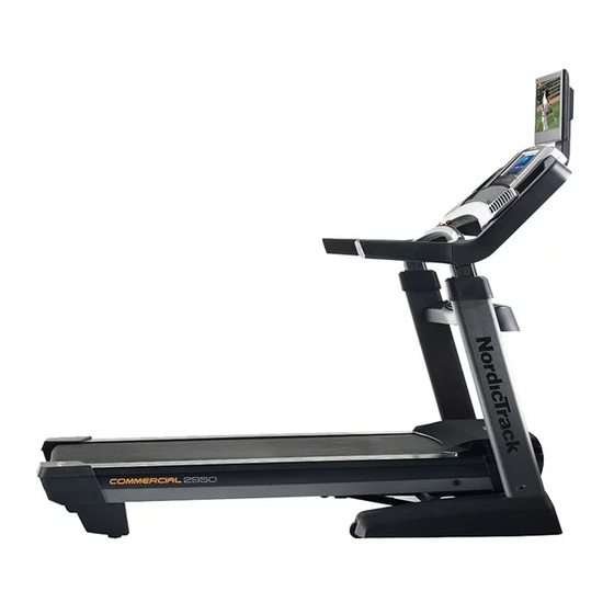
Model No. NTL22113.0
Serial No.
Write the serial number in the space
above for reference.
Serial Number
Decal
ACTIVATE YOUR
WARRANTY
To register your product and
activate your warranty today, go
to www.nordictrackservice.com/
registration.
CUSTOMER CARE
For service at any time, go to
www.nordictrackservice.com.
Or call 1-800-TO-BE-FIT
(1-800-862-3348)
Mon.–Fri. 6 a.m.–6 p.m. MT
Sat. 8 a.m.–12 p.m. MT
Please do not contact the store.
CAUTION
Read all precautions and instruc-
tions in this manual before using
this equipment. Save this manual
for future reference.
USER'S MANUAL
Advertisement
Table of Contents
Troubleshooting

Related Manuals for NordicTrack Commercial 2950 NTL22113.0


Summary of Contents for NordicTrack Commercial 2950 NTL22113.0
- Page 1 USER’S MANUAL Model No. NTL22113.0 Serial No. Write the serial number in the space above for reference. Serial Number Decal ACTIVATE YOUR WARRANTY To register your product and activate your warranty today, go to www.nordictrackservice.com/ registration. CUSTOMER CARE For service at any time, go to www.nordictrackservice.com.
-
Page 2: Table Of Contents
Apply the decal in the location shown. Note: The decals may not be shown at actual size. 305284 NORDICTRACK is a registered trademark of ICON Health & Fitness, Inc. -
Page 3: Important Precautions
22. To purchase a surge suppressor, see your local 4. The treadmill is intended for home use only. NORDICTRACK dealer, call the telephone Do not use the treadmill in any commercial, number on the front cover of this manual, or rental, or institutional setting. - Page 4 20. The treadmill is capable of high speeds. 28. Over exercising may result in serious injury Adjust the speed in small increments to or death. If you feel faint, if you become short avoid sudden jumps in speed.The heart rate of breath, or if you experience pain while monitor is not a medical device.
- Page 5 34. Upon completion of any service or repairs to 38. Use a jumper wire not smaller than No. 6 the treadmill or the television, ask the ser- AWG (13.3 mm ) copper, or the equivalent, vice technician to perform safety checks to when a separate antenna-grounding elec- confirm that the unit is in proper operating trode is used.
- Page 7 STANDARD SERVICE PLANS...
-
Page 8: Before You Begin
BEFORE YOU BEGIN Thank you for selecting the revolutionary reading this manual, please see the front cover of this NORDICTRACK COMMERCIAL 2950 treadmill. manual. To help us assist you, please note the product ® The COMMERCIAL 2950 treadmill offers an impres- model number and serial number before contacting us. -
Page 9: Part Identification Chart
PART IDENTIFICATION CHART Use the drawings below to identify small parts used for assembly. The number in parentheses below each draw- ing is the key number of the part, from the PART LIST near the end of this manual. The number following the key number is the quantity used for assembly. - Page 10 ASSEMBLY • Assembly requires two persons. • To identify small parts, see page 9. • Place all parts in a cleared area and remove the • Assembly requires the following tools: packing materials. Do not dispose of the packing materials until you finish all assembly steps. the included hex key •...
- Page 11 3. Insert the fan wire (A) into the left Upright (84). Slide the Left Base Cover (89) onto the left Upright (84), and slide the Right Base Cover (90) onto the right Upright. Tip: You may need to use a flat screwdriver to pull the Left Base Cover away from the left Upright so that the Left Base Cover will slide over the welded plate (B).
- Page 12 5. Identify the #8 x 3/4" Screws (5). IMPORTANT: Do not confuse the #8 x 3/4" Screws with the #8 x 3/4" Truss Head Screws (24). The #8 x 3/4" Truss Head Screws have flatter heads. Attach the Tray (79) to the left and right Tray Brackets (76) with four #8 x 3/4"...
- Page 13 8. Set the console assembly (E) face down on a soft surface to avoid scratching the console assembly. Remove and discard the four indicated screws (F). Then, remove the Pulse Crossbar (80). 9. IMPORTANT: To avoid damaging the Pulse Crossbar (80), do not use power tools, and do not overtighten the #10 x 3/4"...
- Page 14 10. With the help of a second person, hold the con- sole assembly (E) near the Handrails (74). See the inset drawing. Connect the Upright Wire (83) to the console wire (G). The connec- tors should slide together easily and snap into place.
- Page 15 12. Identify the #8 x 3/4" Screws (5). IMPORTANT: Do not confuse the #8 x 3/4" Screws (5) with the #8 x 3/4" Truss Head Screws (24). The #8 x 3/4" Truss Head Screws have flatter heads. Start four #8 x 3/4" Screws (5) into the Pulse Crossbar (80), and then tighten them.
-
Page 16: Have A Second Person Hold The Frame Until
14. Raise the Frame (52) to the position shown. Have a second person hold the Frame until step 15 is completed. Orient the Storage Latch (56) so that the decal is facing away from the treadmill as shown. Attach the lower end of the Storage Latch (56) to the bracket on the base of the Upright (84) with a 5/16"... - Page 17 16. Set the TV (102) face down on a soft surface to avoid scratching the TV. Remove and save the four M4 x 12mm Screws (130). 17. Insert the wires from the TV (102) through the hole in the TV Bracket (131) as shown. See drawing 17b.
- Page 18 19. Remove and discard the four indicated screws (K). Assembly Remove and save the four indicated 5/16" x 3/4" Screws (1). Hold the TV assembly near the console assembly (E). Connect the two wires on the TV assembly to the two wires on the console Wires assembly.
- Page 19 Before operating the TV, you must connect an antenna or a 75 ohm CATV cable to the 75 ohm terminal, an AV cable to the audio/video input jack, or an HDMI cable to the HDMI input jack. Note: Use a CATV cable to connect to an external source such as a cable box, satellite TV box, VCR, or analog cable.
- Page 20 HOW TO CONNECT A VCR, DVD PLAYER, OR HOW TO CONNECT A DVD OR BLU-RAY PLAYER OTHER DEVICE USING AN AV CABLE OR OTHER DEVICE USING AN HDMI CABLE 1. Connect the three-pronged end of an RCA AV 1. Connect one end of an HDMI cable to your DVD or cable to your VCR, DVD player, or other device.
-
Page 21: The Chest Heart Rate Monitor
THE CHEST HEART RATE MONITOR HOW TO PUT ON THE HEART RATE MONITOR • Do not expose the heart rate monitor to direct sun- light for extended periods of time; do not expose it to The heart rate temperatures above 122° F (50° C) or below 14° F monitor consists of (-10°... -
Page 22: How To Use The Treadmill
HOW TO USE THE TREADMILL HOW TO CONNECT THE POWER CORD nominal 120-volt circuit capable of carrying 15 or more amps. To avoid overloading the circuit, do Use a Surge Suppressor not plug other electrical devices, except for low- power devices such as cell phone chargers, into Your treadmill, like other electronic equipment, can be the surge suppressor or into an outlet on the same circuit. - Page 23 CONSOLE DIAGRAM MAKE YOUR FITNESS GOALS A REALITY WITH FEATURES OF THE CONSOLE IFIT.COM The advanced treadmill console offers an array of fea- With your new iFit-compatible fitness equipment, you tures designed to make your workouts more effective can use an array of features on iFit.com to make your and enjoyable.
- Page 24 HOW TO TURN ON THE POWER Note: The console can display speed and distance in either miles or kilometers. To find which unit of mea- IMPORTANT: If the treadmill has been exposed to surement is selected, see step 4 on page 31. For cold temperatures, allow it to warm to room tem- simplicity, all instructions in this section refer to miles.
- Page 25 HOW TO SET UP THE CONSOLE To use the equipment settings mode, see page 31. To use the sound system, see page 32. To use the Before using the treadmill for the first time, set up the Internet browser, see page 33. To use the main- tenance mode, see page 33.
- Page 26 the screen. The walking belt will begin to move As you walk or run on the treadmill, the screen can at 1 mph. As you exercise, change the speed of show the following workout information: the walking belt as desired by pressing the Speed increase and decrease buttons.
- Page 27 To measure your heart rate, stand on the foot HOW TO USE AN ONBOARD WORKOUT rails and hold the contacts with your palms for approximately ten seconds; avoid moving your 1. Insert the key into the console. hands. When your pulse is detected, your heart rate will be shown.
- Page 28 7. When you are finished exercising, remove the The workout will continue in this way until the last segment ends. The walking belt will then slow to key from the console. a stop and a workout summary will appear on the screen.
- Page 29 HOW TO USE AN IFIT WORKOUT The workout will continue until you reach the goal that you set. The walking belt will then slow to a stop, and a workout summary will appear on the Note: To use an iFit workout, you must have access screen.
- Page 30 6. Monitor your progress with the displays. To compete in a race that you have previously scheduled, touch the Compete button. To view your Workout History, touch the Track button. To use a See step 5 on page 26. The screen may also set-a-goal workout, touch the Set A Goal button show a map of the trail you are walking or running.
- Page 31 HOW TO USE THE EQUIPMENT SETTINGS MODE 6. Select an update time. 1. Select the settings main menu. To select a time for automatic firmware updates, touch the Update Time button and select the Insert the key into the console desired time.
- Page 32 9. Enable or disable the street view. To set the amount of time the console will wait before it automatically resets, touch the Safety During some workouts, the screen may show a Screen Timeout button to view a list of times. Then, map.
- Page 33 HOW TO CHANGE THE AUDIO INPUT HOW TO USE THE MAINTENANCE MODE To select a different audio source, touch the music 1. Select the settings main menu. notes button at the bottom of the screen. Then, choose an audio source from the list. Note: Select Personal TV See step 1 on page 31.
- Page 34 4. Calibrate the incline system of the treadmill. 3. Enable Wi-Fi. Touch the Calibrate Incline button. Then, touch the Make sure that the Wi-Fi checkbox is marked with Begin button to calibrate the incline system. The a green checkmark. If it is not, touch the Wi-Fi treadmill will automatically rise to the maximum menu option once and wait for a few seconds.
- Page 35 If you are having problems connecting to an When the buttons are pressed, a graphic will encrypted network, make sure that your password appear on-screen to show which channel is is correct. Note: Passwords are case-sensitive. selected. Note: The iFit mode supports unsecured and Note: The digital TV can identify and store in secured (WEP, WPA, and WPA2) encryption.
- Page 36 HOW TO USE THE ENTERTAINMENT MODE Press the Mute button to turn on or turn off the sound. The console features an entertainment mode that Press the numbered channel buttons and the dash allows you to access an on-screen remote control. button (–) or the Channel (CH) increase or decrease button to select a channel.
- Page 37 HOW TO REPLACE THE BATTERIES IN THE navigate through the various settings and person- REMOTE CONTROL alize the image settings. 3. Adjust the audio settings. To replace the batteries, first locate the battery cover on the back of the The Audio menu offers numerous features for remote control.
- Page 38 5. Adjust the parental control settings. Select Menu Language to change the language used in the menus. The Parental menu allows you to block or allow various settings on the TV. Select Clock to adjust the TV clock’s time zone, auto setting, time setting, day of the week setting, First, enter the Lock Parental Code password, and daylight saving time setting.
-
Page 39: How To Fold And Move The Treadmill
HOW TO FOLD AND MOVE THE TREADMILL HOW TO FOLD THE TREADMILL HOW TO MOVE THE TREADMILL To avoid damaging the treadmill, adjust the incline Before moving the treadmill, fold it as described at the to zero before you fold the treadmill. Then, remove left. -
Page 40: Maintenance And Troubleshooting
MAINTENANCE AND TROUBLESHOOTING MAINTENANCE SYMPTOM: The power turns off during use Regularly clean the treadmill and keep the walking a. Check the power switch (see drawing c at the left). belt clean and dry. First, press the power switch into If the switch has tripped, wait for five minutes and the off position and unplug the power cord. - Page 41 SYMPTOM: The walking belt slows when walked on Locate the Reed Switch (47) and the Magnet (45) on the left side of the Pulley (51). Turn the Pulley until the Magnet is aligned with the Reed Switch. a. Use only a surge suppressor that meets all of the Make sure that the gap between the Magnet specifications described on page 22.
- Page 42 b. If the walking belt slips when walked on, first c. Your treadmill features a walking belt coated with high-performance lubricant. IMPORTANT: Never remove the key and UNPLUG THE POWER apply silicone spray or other substances to CORD. Using the hex key, turn both idler roller the walking belt or the walking platform unless screws clockwise, 1/4 of a turn.
- Page 43 SYMPTOM: Digital TV reception is poor • Fading—If blocks of the picture are missing, the picture moves around the screen, or the picture a. Make sure that the digital TV settings are set cor- disappears, the signal may be weak. Change the rectly.
-
Page 44: Exercise Guidelines
EXERCISE GUIDELINES Burning Fat—To burn fat effectively, you must exer- WARNING: cise at a low intensity level for a sustained period of Before beginning this time. During the first few minutes of exercise, your or any exercise program, consult your physi- body uses carbohydrate calories for energy. -
Page 45: Part List
PART LIST Model No. NTL22113.0 R0514B Key No. Qty. Description Key No. Qty. Description 5/16" x 3/4" Screw Drive Roller/Pulley 5/16" x 2" Screw Frame 5/16" x 1 3/4" Bolt 5/16" x 2 1/4" Bolt Drive Motor #8 x 3/4" Screw Motor Belt #10 x 3/4"... - Page 46 Key No. Qty. Description Key No. Qty. Description Right Tray Cushion Wheel Stop Tray Fan Upper TV Bracket Cover Tray Fan Cover Key/Clip 2.5A Power Supply Console Frame Cap Stand-off Console Frame Power Supply Plate Wire Tie M4 x 12mm Screw Pulse Strap TV Bracket Heart Rate Monitor...
-
Page 47: Exploded Drawing
EXPLODED DRAWING A Model No. NTL22113.0 R0514B... - Page 48 EXPLODED DRAWING B Model No. NTL22113.0 R0514B 33 112 33 117 115 111...
- Page 49 EXPLODED DRAWING C Model No. NTL22113.0 R0514B...
- Page 50 EXPLODED DRAWING D Model No. NTL22113.0 R0514B...
- Page 51 EXPLODED DRAWING E Model No. NTL22113.0 R0514B...
-
Page 52: Limited Warranty
ORDERING REPLACEMENT PARTS To order replacement parts, please see the front cover of this manual. To help us assist you, be prepared to provide the following information when contacting us: • the model number and serial number of the product (see the front cover of this manual) •...