Table of Contents
Advertisement
Quick Links
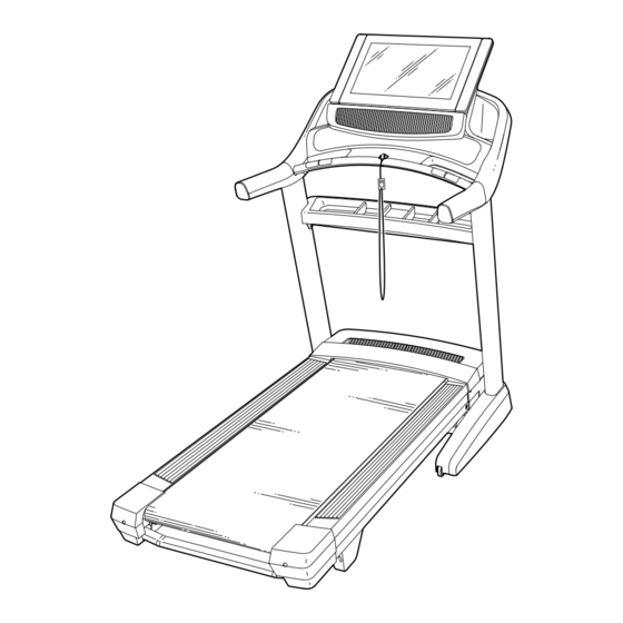
Model No. NETL28719.0
Serial No.
USER'S MANUAL
Write the serial number in the space
above for reference.
Serial Number
Decal
CUSTOMER SERVICE
UNITED KINGDOM
Call: 0330 123 1045
From Ireland: 053 92 36102
Website: iconsupport.eu
E-mail: csuk@iconeurope.com
Write:
ICON Health & Fitness, Ltd.
Unit 4, Westgate Court
Silkwood Park
OSSETT
WF5 9TT
UNITED KINGDOM
AUSTRALIA
Call: 1800 993 770
E-mail: australiacc@iconfitness.com
Write:
ICON Health & Fitness
PO Box 635
WINSTON HILLS NSW 2153
AUSTRALIA
CAUTION
Read all precautions and
instructions in this manual before
using this equipment. Save this
manual for future reference.
iconeurope.com
Advertisement
Table of Contents

Related Manuals for NordicTrack NETL28719.0


Summary of Contents for NordicTrack NETL28719.0
- Page 1 Model No. NETL28719.0 Serial No. USER’S MANUAL Write the serial number in the space above for reference. Serial Number Decal CUSTOMER SERVICE UNITED KINGDOM Call: 0330 123 1045 From Ireland: 053 92 36102 Website: iconsupport.eu E-mail: csuk@iconeurope.com Write: ICON Health & Fitness, Ltd.
-
Page 2: Table Of Contents
Note: The decals may not be shown at actual size. 305284 NORDICTRACK and IFIT are registered trademarks of ICON Health & Fitness, Inc. Wi-Fi is a registered trademark of Wi-Fi Alliance. WPA and WPA2 are trademarks of Wi-Fi Alliance. The Bluetooth word mark and ®... -
Page 3: Important Precautions
IMPORTANT PRECAUTIONS WARNING: To reduce the risk of burns, fire, electric shock, or injury to persons, read all important precautions and instructions in this manual and all warnings on your treadmill before using your treadmill. ICON assumes no responsibility for personal injury or property damage sus- tained by or through the use of this product. - Page 4 21. The treadmill is capable of high speeds. frame securely in the storage position. Do Adjust the speed in small increments to not operate the treadmill while it is folded. avoid sudden jumps in speed. 26. Do not change the incline of the treadmill by 22.
-
Page 5: Before You Begin
BEFORE YOU BEGIN Thank you for selecting the revolutionary reading this manual, please see the front cover of this NORDICTRACK COMMERCIAL 2950 treadmill. manual. To help us assist you, please note the product ® The COMMERCIAL 2950 treadmill offers an impres- model number and serial number before contacting us. -
Page 6: Part Identification Chart
PART IDENTIFICATION CHART Use the drawings below to identify small parts used for assembly. The number in parentheses below each draw- ing is the key number of the part, from the PART LIST near the end of this manual. The number following the key number is the quantity used for assembly. -
Page 7: Assembly
ASSEMBLY • Assembly requires two persons. • Left parts are marked “L” or “Left” and right parts are marked “R” or “Right.” • Place all parts in a cleared area and remove the packing materials. Do not dispose of the packing •... - Page 8 2. Make sure that the power cord is unplugged. Remove the tie securing the Upright Wire (83) to the front of the Base (93). Next, identify the Right Upright (84). Have a second person hold the Right Upright near the Base (93).
- Page 9 4. Hold the Right Upright (84) against the Base (93). Do not pinch the Upright Wire (83). Attach the Right Upright (84) with two 3/8" x 2 3/4" Screws (23), two 3/8" x 1 1/4" Screws (20), and four 3/8" Star Washers (25) as shown; do not fully tighten the Screws yet.
- Page 10 6. Carefully slide the Upright Crossbar (76) between the Right and Left Uprights (84, 91). Attach the Upright Crossbar with four 5/16" x 3/4" Screws (1); start all four Screws, and then tighten them. 7. Attach the Tray (79) to the Upright Crossbar (76) with four #8 x 3/4"...
- Page 11 8. Attach the two Handrails (74) to the Right and Left Uprights (84, 91) with two 5/16" x 2" Screws (2) and two 5/16" Star Washers (8); do not fully tighten the Screws yet. Do not pinch the Upright Wire (83) on the right side. Position the Upright Wire in the notch (F) as shown.
- Page 12 10. IMPORTANT: To avoid damaging the Pulse Crossbar (80), do not use power tools, and do not overtighten the #10 x 3/4" Screws (6) or the 5/16" x 2" Screws (2). Orient the Pulse Crossbar (80) as shown. Attach the Pulse Crossbar to the Handrails (74) with two 5/16"...
- Page 13 12. Attach the console assembly (H) to the Handrails (74) with four 5/16" x 2" Screws (2) and four 5/16" Star Washers (8); start all four Screws, and then tighten them. Do not pinch the wires (J). Insert the wires (J) into the top of the Right Upright (84).
- Page 14 14. Start eight #8 x 3/4" Truss Head Screws (24) into the Pulse Crossbar (80), and then tighten them; do not overtighten the Truss Head Screws. 15. Set the Left Handrail Top Cover (73) on the left Handrail (74). Start four #8 x 3/4" Truss Head Screws (24) into the Left Handrail Bottom Cover (75), the left Handrail, and the Left Handrail Top Cover.
- Page 15 16. Raise the Frame (52) to the upright position. Have a second person hold the Frame until step 18 is completed. Remove the two 5/16" x 1 1/4" Screws (16) from the Latch Crossbar (109). Orient the Latch Crossbar (109) as shown. Make sure that the “This side toward belt”...
- Page 16 18. Remove the 5/16" Nut (9) and the 5/16" x 2 1/4" Bolt (4) from the bracket on the Frame (52). Align the upper end of the Storage Latch (56) with the bracket on the Frame (52), and insert the 5/16" x 2 1/4" Bolt (4) through the bracket and the Storage Latch.
-
Page 17: The Chest Heart Rate Monitor
THE CHEST HEART RATE MONITOR HOW TO PUT ON THE HEART RATE MONITOR • Store the heart rate monitor in a warm, dry place. Do not store the heart rate monitor in a plastic bag or If the heart rate monitor looks like the one shown other container that may trap moisture. -
Page 18: How To Use The Treadmill
HOW TO USE THE TREADMILL HOW TO PLUG IN THE POWER CORD Follow the steps below to plug in the power cord. This product must be earthed. If it should malfunc- 1. Plug the indicated end of the power cord (A) into the tion or break down, earthing provides a path of least socket (B) on the treadmill. - Page 19 CONSOLE DIAGRAM FEATURES OF THE CONSOLE rate using the handgrip heart rate monitor or the chest heart rate monitor. The advanced treadmill console offers a selection of features designed to make your workouts more effec- In addition, the console features a selection of tive and enjoyable.
- Page 20 HOW TO TURN ON THE POWER HOW TO USE THE TOUCH SCREEN IMPORTANT: If the treadmill has been exposed to The console features a tablet with a full-color touch cold temperatures, allow it to warm to room tem- screen. The following information will help you become perature before you turn on the power.
- Page 21 HOW TO SET UP THE CONSOLE 6. Calibrate the incline system. Before using the treadmill for the first time, set up the First, touch your name on the screen. Next, select console. the settings main menu. Then, select the mainte- nance section, touch the Calibrate Incline button, 1.
- Page 22 HOW TO USE THE MANUAL MODE 4. Change the incline of the treadmill as desired. 1. Insert the key into the console. To change the incline of the treadmill, press the Incline increase and decrease buttons or one of the See HOW TO TURN ON THE POWER on numbered incline buttons.
- Page 23 To measure your heart rate, stand on the foot • Your pace rails and hold the contacts with your palms for • The speed of the walking belt approximately ten seconds; avoid moving your hands. When your pulse is detected, your heart rate will be shown.
- Page 24 HOW TO USE A MAP WORKOUT 5. Monitor your progress with the display modes. Note: To use a map workout, the console must be con- See step 5 on page 22. nected to a wireless network (see HOW TO USE THE 6.
- Page 25 HOW TO USE A DISTANCE OR TIME WORKOUT If you make a mistake, you can use the Undo but- ton on the left side of the screen. Note: To use a distance or time workout, the console The screen will display the elevation and distance must be connected to a wireless network (see HOW statistics for your workout.
- Page 26 6. Start the workout. 2. Select the workout section. Touch the Start button to start the workout. A In the settings main menu, scroll to the Workout moment after you touch the button, the walking belt section. will begin to move. Hold the handrails and begin walking.
- Page 27 HOW TO USE THE MAINTENANCE SECTION IMPORTANT: Keep pets, feet, and other objects away from the treadmill while the incline sys- 1. Select the settings main menu. tem is calibrating. In an emergency, pull the key from the console to stop the incline calibration. See step 1 on page 26.
- Page 28 HOW TO USE THE SOUND SYSTEM WITH A An information box will ask if you want to connect to the wireless network. Touch the Connect button BLUETOOTH DEVICE to connect to the network or touch the Cancel but- 1. Place or hold your Bluetooth-enabled device ton to return to the list of networks.
- Page 29 HOW TO ADJUST THE ANGLE OF THE CONSOLE HOW TO ADJUST THE CUSHIONS To adjust the angle of the console, hold both sides of The treadmill features cushions that reduce the impact the console and tilt it to the desired position. as you walk or run on the treadmill.
-
Page 30: How To Fold And Move The Treadmill
HOW TO FOLD AND MOVE THE TREADMILL HOW TO FOLD THE TREADMILL HOW TO MOVE THE TREADMILL To avoid damaging the treadmill, adjust the incline Before moving the treadmill, fold it as described at the to zero before you fold the treadmill. Then, remove left. -
Page 31: Maintenance And Troubleshooting
MAINTENANCE AND TROUBLESHOOTING MAINTENANCE SYMPTOM: The power turns off during use Regular maintenance is important for optimal perfor- a. Check the power switch (see drawing c at the left). mance and to reduce wear. Inspect and properly tighten If the switch has tripped, wait for five minutes and all parts each time the treadmill is used. - Page 32 SYMPTOM: The displays of the console do not SYMPTOM: The walking belt slows when walked on function properly a. If an extension cord is needed, use only a 3-conduc- a. Remove the key from the console and UNPLUG tor, 14-gauge (2 mm ) cord that is no longer than THE POWER CORD.
- Page 33 SYMPTOM: The walking belt is not centred SYMPTOM: The displays of the console do not between the foot rails function properly IMPORTANT: If the walking belt rubs against a. If the console does not boot up properly, or if the the foot rails (B), the walking belt may become console freezes and does not respond, reset the damaged.
- Page 34 SYMPTOM: The console does not stay in place a. If the console does not stay in the desired position because it is too loose, use a hex key to slightly tighten the console in the indicated location on both sides (only one side is shown).
-
Page 35: Exercise Guidelines
EXERCISE GUIDELINES Burning Fat—To burn fat effectively, you must exer- WARNING: cise at a low intensity level for a sustained period of Before beginning this time. During the first few minutes of exercise, your or any exercise program, consult your physi- body uses carbohydrate calories for energy. - Page 36 SUGGESTED STRETCHES The correct form for several basic stretches is shown at the right. Move slowly as you stretch —never bounce. 1. Toe Touch Stretch Stand with your knees bent slightly and slowly bend forward from your hips. Allow your back and shoulders to relax as you reach down toward your toes as far as possible.
- Page 37 NOTES...
-
Page 38: Part List
PART LIST Model No. NETL28719.0 R0919A Key No. Qty. Description Key No. Qty. Description 5/16" x 3/4" Screw Drive Roller/Pulley 5/16" x 2" Screw Frame 5/16" x 1 3/4" Bolt 5/16" x 2 1/4" Bolt Drive Motor #8 x 3/4" Screw Motor Belt #10 x 3/4"... - Page 39 Key No. Qty. Description Key No. Qty. Description Right Tray Cushion Wheel Stop Hood Accent M10 Spring Washer Hood Grill Cushion Wheel Key/Clip 3/8" Flat Washer Console Frame Cap 1/4" x 1/2" Screw Console Frame 1/4" x 1 1/2" Bolt Cable Tie Wire Tie Cushion Rod...
-
Page 40: Exploded Drawing
EXPLODED DRAWING A Model No. NETL28719.0 R0919A... - Page 41 EXPLODED DRAWING B Model No. NETL28719.0 R0919A...
- Page 42 EXPLODED DRAWING C Model No. NETL28719.0 R0919A...
- Page 43 EXPLODED DRAWING D Model No. NETL28719.0 R0919A...
-
Page 44: Ordering Replacement Parts
ORDERING REPLACEMENT PARTS To order replacement parts, please see the front cover of this manual. To help us assist you, be prepared to provide the following information when contacting us: • the model number and serial number of the product (see the front cover of this manual) •...