
Related Manuals for Toshiba NB100


Summary of Contents for Toshiba NB100
- Page 1 Toshiba Personal Computer TOSHIBA NB100 (PLL10X-XXXXX) Maintenance Manual TOSHIBA CORPORATION S/ No Libretto L100/L105/Satellite UX/TOSHIBA NB100 Maintenance Manual...
- Page 2 © 2008 by Toshiba Corporation. All rights reserved. Under the copyright laws, this manual cannot be reproduced in any form without the prior written permission of Toshiba. No patent liability is assumed with respect to the use of the information contained herein.
- Page 3 Preface This maintenance manual describes how to perform hardware service maintenance for the Toshiba Personal Computer TOSHIBA NB100 , referred to as TOSHIBA NB100 in this manual. The procedures described in this manual are intended to help service technicians isolate faulty Field Replaceable Units (FRUs) and replace them in the field.
- Page 4 The manual is divided into the following parts: Chapter 1 Hardware Overview describes the TOSHIBA NB100 system unit and each FRU. Chapter 2 Troubleshooting Procedures explains how to diagnose and resolve FRU problems. Chapter 3 Test and Diagnostics describes how to perform test and diagnostic operations for maintenance service.
- Page 5 Text that you are instructed to type in is shown in the boldface type below: DISKCOPY A: B: The display Text generated by the XXXXX that appears on its display is presented in the type face below: Format complete System transferred TOSHIBA NB100 Maintenance Manual...
-
Page 6: Table Of Contents
Procedure 2 Partition Check ..............2-11 Procedure 3 Format Check................2-12 Procedure 4 Test Program Check ............... 2-13 Procedure 5 Connector Check and Replacement Check......2-14 Keyboard ......................2-15 Procedure 1 Test Program Check ..............2-15 TOSHIBA NB100 Maintenance Manual 4-iii... - Page 7 Exit to Free DOS ........Error! Bookmark not defined. 3.2.10 3.2.11 The Diagnostics Screen Explanation..Error! Bookmark not defined. Options ..............Error! Bookmark not defined. 3.3.1 Overview ..........Error! Bookmark not defined. 3.3.2 Batch Parameters Configuration ....Error! Bookmark not defined. 4-iv TOSHIBA NB100 Maintenance Manual...
- Page 8 Colors of Screw Shanks ..................4-7 Symbols of Screws on the Computer Body ............4-7 Symbol examples ....................4-7 Removing the Battery Pack ................. 4-8 Installing the Battery Pack................... 4-9 Removing the Momery Card ................4-10 TOSHIBA NB100 Maintenance Manual...
- Page 9 CCD board and Speakers ..................4-36 Removing the CCD board and Speakers ............4-36 Installing the CCD board and Speakers ............. 4-37 4.11 Touch Pad Board ....................4-38 Removing the Touch Pad Board ................ 4-38 4-iv TOSHIBA NB100 Maintenance Manual...
- Page 10 4 Replacement Procedure Installing the Touch Pad Board ................. 4-39 TOSHIBA NB100 Maintenance Manual...
- Page 11 4 Replacement Procedures Appendices Appendix A Handling the LCD Module ................A-1 Appendix B Board Layout ....................B-1 Appendix C Pin Assignments.................... C-1 Appendix D Keyboard Scan/Character Codes ..............D-1 Appendix E Key Layout.....................E-1 4-iv TOSHIBA NB100 Maintenance Manual...
-
Page 12: Hardware Overview
Chapter 1 Hardware Overview TOSHIBA NB100 Maintenance Manual... - Page 13 1 Hardware Overview TOSHIBA NB100 Maintenance Manual...
- Page 14 System Unit Components ................... 11 2.5-inch HDD......................16 Solid State Drive (SSD) ....................17 Power Supply ......................18 Batteries ........................19 1.6.1 Main Battery..................19 1.6.2 Battery Charging Control ..............19 1.6.3 RTC Battery ..................20 TOSHIBA NB100 Maintenance Manual...
- Page 15 Figure 1-4 System Unit Block Diagram ..................11 Figure 1-5 SATA HDD ......................16 Figure 1-6 Solid state driver ....................17 Table Table 1-1 HDD Specifications ....................16 Table 1-2 SSD Specifications....................17 Table 1-3 Battery specifications....................19 Table 1-4 Quick/Normal charging time ..................19 TOSHIBA NB100 Maintenance Manual...
- Page 16 1 Hardware Overview Features The Toshiba Arizona is a B5 size notebook PC based on the ATOM processor, providing high- speed processing capabilities and advanced features. The computer employs a Lithium Ion battery that allows it to be battery-operated for a longer period of time. The display uses 8.9- inch WSGA LCD panel, at a resolution of 1280 by 600 pixels...
- Page 17 SD/ Mini-SD/ Micro-SD/ SD-IO/ SDHC/ MS/ MS Pro/ MMC memory cards. This slot is for your memory card requirements to provide memory card read on your computer Toshiba Pointing Device Toshiba Pointing Device has one kind of Normal touchpad and one kind of touch pad. TOSHIBA NB100 Maintenance Manual...
-
Page 18: Features
The internal Mini Card slot supports IEEE802.11bg. The Antenna has two dual band antennas. Internal Camera (BTO) The computer has an internal camera. The camera has VGA (fixed focus) for low end ID or 1.3Mpix resolution (fixed focus) for mainstream ID support. TOSHIBA NB100 Maintenance Manual... -
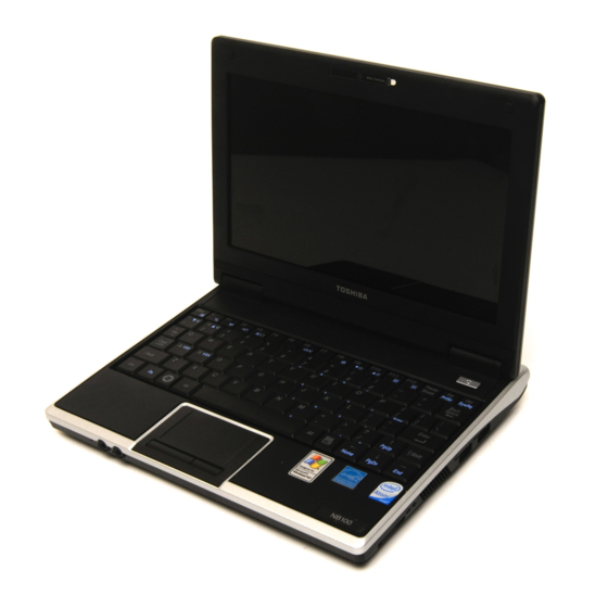
Page 19: Figure 1-1 Id Parts Description Placement
1 Hardware Overview 1.1 Features Figures 1-1/1-2/1-3 and 1-4 show the computer and its system unit configuration, respectively. Figure 1-1 ID Parts Description Placement TOSHIBA NB100 Maintenance Manual... -
Page 20: Figure 1-2 Computer Block Diagram
1.1 Features 1 Hardware Overview Figure 1-2 Computer Block Diagram TOSHIBA NB100 Maintenance Manual... -
Page 21: Figure 1-3 System Board Configurations
1 Hardware Overview 1.1 Features Figure 1-3 System Board Configurations TOSHIBA NB100 Maintenance Manual... -
Page 22: System Unit Components
1.2 System Unit Components 1 Hardware Overview System Unit Components Figure 1-4 is Block Diagram of the System Unit. Figure 1-4 System Unit Block Diagram TOSHIBA NB100 Maintenance Manual... - Page 23 − FV02 free space : 4K − FV03 size : 20K − FV03 free space : 2K − FV04 size : 72K − FV04 free space : 15K System Controllers North Bridge: Intel 945GSE − CPU Interface and Control TOSHIBA NB100 Maintenance Manual...
- Page 24 − SD/Mini SD/SD-IO/MS/MS Pro/MMC Card Controller − PCI Bus interface Audio Controller Realtek ALC262 integrated audio controller supports multimedia. The sound system feature contains the following: 2 Stereo DACs support 16/20/24-bit PCM format for stereo audio playback. TOSHIBA NB100 Maintenance Manual...
- Page 25 − I2C communication control Battery EEPROM 24C02 equivalent (128 words x 16 bits, I2C interface) integrated in battery pack. − Storing records of battery use Clock Generator ICS9LPRS501 − Generating the clock signal required for the system. TOSHIBA NB100 Maintenance Manual...
- Page 26 − Remote boot (PXE 2.1) − Smart power down when link is not detected Wireless LAN Controller Support following mini PCI wireless LAN cards − IEEE 802.11bg Data Rate − IEEE 802.11bg: Standard 54M bps Frequency Channel − IEEE802.11bg: 2.4GHz TOSHIBA NB100 Maintenance Manual...
-
Page 27: Inch Hdd
Table 1-1 HDD Specifications Item Specifications Capacity (GB) 80 GB 120 GB 160 GB Rotational Speed (RPM) 5400 rpm 5400 rpm 5400 rpm Height 9.5 mm 9.5 mm 9.5 mm User Data Sectors 156,301,488 234,442,648 312,581,808 Bytes / Sector TOSHIBA NB100 Maintenance Manual... -
Page 28: Solid State Drive (Ssd)
The SSD is shown in Figure 1-6 and some of its specifications are listed in Table 1-2. Figure 1-6 Solid state driver Table 1-2 SSD Specifications Item Specifications Capacity (GB) 4 GB Total bytes 4,096,253,952 Cylinders 7937 Head Sector Max LBA 8,000,496 TOSHIBA NB100 Maintenance Manual... -
Page 29: Power Supply
Monitors the voltage output to the system block (load/logic circuit side). Monitors the voltage, over voltage, input/output current of the battery pack. Monitors the internal temperature of the battery pack. Monitors the supply voltage from the AC adapter. TOSHIBA NB100 Maintenance Manual... -
Page 30: Batteries
1.6 5BBatteries 1 Hardware Overview Batteries The computer has the following three types of batteries: Main Battery Pack Real Time Clock (RTC) Battery Table 1-5 lists the specifications of these batteries. Table 1-3 Battery specifications Battery Type Material Output voltage Capacity 4 Cell Lithium Ion... -
Page 31: Rtc Battery
1. The current in the battery charging circuit drops below the predetermined value. 2. The charging time exceeds the fixed limit. 1.6.3 RTC Battery The RTC battery provides power to keep the current date, time and other system information in memory while the computer is turned off. TOSHIBA NB100 Maintenance Manual... -
Page 32: Troubleshooting
2 Troubleshooting 概要 Chapter 2 Troubleshooting TOSHIBA NB100 Maintenance Manual... - Page 33 Audio Test ......................2-19 Procedure 1 Test Program Check ..............2-19 Procedure 2 Connector Check and Replacement Check........ 2-19 2.10 Cooling Module....................2-20 Procedure 1Test Program Check ..............2-20 Procedure 2Connector Check and Replacement Check......... 2-20 2-ii TOSHIBA NB100 Maintenance Manual...
- Page 34 2 Troubleshooting TOSHIBA NB100 Maintenance Manual 2-iii...
- Page 35 2 Troubleshooting Figures Figure 2-1 Basic flowchart ....................2-3 Tables Table 2-1 HDD error code and status................2-13 2-iv TOSHIBA NB100 Maintenance Manual...
-
Page 36: Outline
4. Cleaning disk kit (for USB ODD drive cleaning) 5. Bootable CD 6. Multimeter 7. External monitor 8. Headphone 9. Microphone 10. A-BEX TEST DVD 11. Music CD 12. DVD TSD-1 (TOSHIBA EMI DVD Test Media) TOSHIBA NB100 Maintenance Manual... -
Page 37: Basic Flowchart
Make sure the Windows® XP or Linix has been installed on the HDD. Any other operating system can cause the computer to malfunction. Make sure any piece of optional equipment has been installed. TOSHIBA NB100 Maintenance Manual... - Page 38 Message "In Touch with Tomorrow Toshiba" displayed procedure in Section 2.7 See the previous page to "Password=" displayed ?? delete the password. Follow the HDD diagnostic OS started ?? procedure in Section 2.5 Figure 2-1 Basic flowchart(1/2) TOSHIBA NB100 Maintenance Manual...
- Page 39 Perform the continuous test to check if the error is intermittent. Identify the test resulting in the Any error detected by the error and perform the appropriate diagnostic program ?? diagnostic procedures The system is normal. Figure 2-1 Basic flowchart (2/2) TOSHIBA NB100 Maintenance Manual...
- Page 40 6. If an error is detected by the Speaker test, follow the Speaker troubleshooting procedures in section 2.9. 7. If an error is detected by the Fan On/Off test, follow the cooling module troubleshooting procedures in Section 2.10. TOSHIBA NB100 Maintenance Manual...
-
Page 41: Power Supply
The power supply controller displays the power supply status through the Battery and DC IN LEDs as in the tables below. Battery LED Battery LED Power supply status Blinking in Green Battery being charged On in Green Battery fully charged, with AC adapter connected Else TOSHIBA NB100 Maintenance Manual... - Page 42 Make sure the DC IN LED goes on in Green If it does not, go to Procedure 2. Check 2 Make sure the Battery LED goes on in Green. If it does not, go to Procedure 3. TOSHIBA NB100 Maintenance Manual...
-
Page 43: System Board
Procedure 3. Procedure 3 Replacement Check The system board may be faulty. Disassemble the computer according to Chapter 4 and follow the steps below: Check 1 Replace the system board with a new one. TOSHIBA NB100 Maintenance Manual... -
Page 44: System Board
The error message appears when either data stored in RAM to be resumed is lost because the battery has been exhausted or the system board is faulty. RESUME FAILURE and PRESS ANY KEY TO CONTINUE. TOSHIBA NB100 Maintenance Manual... -
Page 45: Procedure 3 Replacement Check
If an error is detected during these tests, go to Procedure 3. Procedure 3 Replacement Check The system board, memory, may be defective. Disassemble the computer following the steps described in Chapter 4 and replace the system board, memory module with a new one. 2-10 TOSHIBA NB100 Maintenance Manual... -
Page 46: Hdd
Type FDISK and press the Enter key. Choose “Display partition Check 2 information” from the FDISK menu. If drive C is listed, perform Check 3. If drive C is not listed, return to the FDISK menu and choose the option to TOSHIBA NB100 Maintenance Manual 2-11... -
Page 47: Format Check
Enter FORMAT C:/S/U to format the HDD and transfer system files. If the following message appears on the display, the HDD has been formatted. Format complete If you cannot format the HDD using the test program, go to Procedure 4. 2-12 TOSHIBA NB100 Maintenance Manual... -
Page 48: Test Program Check
Disk Controller Self Test Failed Disk Controller Test unexpected interrupt Failed Disk Controller action Test Failed Disk dos not support SMART Disk read attribute threshold error Disk read attribute value error Disk SMART attribute value error TOSHIBA NB100 Maintenance Manual 2-13... -
Page 49: Connector Check And Replacement Check
The System board may be damaged. Replace it with a new one following the disassembling instructions in Chapter 4. If the problem persists, perform Check 4. Check 4 The system board may be damaged. Replace it with a new one following the disassembling instructions in Chapter 4. 2-14 TOSHIBA NB100 Maintenance Manual... -
Page 50: Keyboard
Chapter 4. If the problem persist, perform Check 5. Check 5 The system board may be faulty. Disassemble the computer following the steps described in Chapter 4 and replace the CPU with a new one. TOSHIBA NB100 Maintenance Manual 2-15... -
Page 51: Display
If any of the cables is loose or off, reconnect it firmly and return to Procedure 3. If there is still an error, perform Check 2. Check 2 The LCD/FL cable may be faulty. Replace it with a new one and return to 2-16 TOSHIBA NB100 Maintenance Manual... - Page 52 The System board may be faulty. Replace it with a new one. If there is still an error, perform Check 9. Check 9 The memory may be defective. Replace the memory module with a new one following the steps described in Chapter 4. TOSHIBA NB100 Maintenance Manual 2-17...
-
Page 53: Lan
Chapter 4. If the problem persists, perform Check 3. Check 3 The system board may be faulty. Disassemble the computer following the steps described in Chapter 4 and replace the system board with a new one 2-18 TOSHIBA NB100 Maintenance Manual... -
Page 54: Audio Test
Chapter 4. If the problem persist, perform Check 5. Check 5 The system board may be faulty. Disassemble the computer following the steps described in Chapter 4 and replace the system board with a new one. TOSHIBA NB100 Maintenance Manual 2-19... -
Page 55: Cooling Module
Chapter 4. If the problem persists, perform Check 4. Check4 The system board may be faulty. Disassemble the computer following the steps described in Chapter 4 and replace the system board with a new one. 2-20 TOSHIBA NB100 Maintenance Manual... - Page 56 2.10Cooling Module 2 Troubleshooting TOSHIBA NB100 Maintenance Manual 2-21...
- Page 57 Chapter 3 Diagnostic Programs...
- Page 58 LOG Parameters Setting................ 21 3.3.7 Specify LOG Viewer................22 3.3.8 Display LOG File .................. 22 3.3.9 LOG Viewer ..................23 3.3.10 LOG File Sample................... 24 Subtests ........................26 System Test......................... 29 Memory Test....................... 34 Storage ........................40 Video........................... 44 TOSHIBA NB100 Maintenance Manual...
- Page 59 3 Diagnostic Programs Communication (COMM) ..................53 3.10 Peripheral ........................54 3.11 Error Codes and description..................57 3.12 Quick Test Item List ...................... i TOSHIBA NB100 Maintenance Manual...
-
Page 61: General
Keyboard Layout Test Audio Play Test Audio Record Test DMI Read DMI Write System Information Before running the diagnostic programs, get the following tools prepared: A Service Diagnostic BOOT CD or Flash Memory A Formatted FLOPPY DISK TOSHIBA NB100 Maintenance Manual... - Page 62 50KB spare space in the drive, system will save all log files into the root directory the diskette; otherwise, system will save all log files in the root directory of RAM disk. TOSHIBA NB100 Maintenance Manual...
-
Page 63: Quick Start
Please see the following example-- Mouse test. Use arrow key to select ‘TouchPad’ item on ‘Peripheral’ in the menu, then press Space key to select it. (When it is being selected, there is a X marked in the TOSHIBA NB100 Maintenance Manual... - Page 64 Select ‘Test Mouse’ or press F8 to run the test. The prompt information would be displayed in the screen as below. This test item needs user to verify whether the mouse works normally. The test result will be displayed in the following screen: TOSHIBA NB100 Maintenance Manual...
- Page 65 CPU Speed Test (Step by Step): Select test item: Select System—CPU—CPU Speed, then, press the Enter key. Parameters Setting Choose the OK button after you set the proper parameters in the following window. TOSHIBA NB100 Maintenance Manual...
- Page 66 Configuration) Then press F8 to start the test. User should configure each parameter in advance; otherwise the default parameters would be used. Using this method, user is allowed to select more than one test item at one time. 2) Running the current test item TOSHIBA NB100 Maintenance Manual...
-
Page 67: Keyboard Layout Test
When users choose the item, the names of these countries will be displayed on the screen for user choice. User press any index of token in ASCII, and the program will test the kind of keymap of the country. The test screen would be shown as below: TOSHIBA NB100 Maintenance Manual... -
Page 68: Audio Play Test
Fail. The test will repeat for four times, if there is no error it return main menu automatically. When the test is completed, a file named autest.log will be saved in the defined location. TOSHIBA NB100 Maintenance Manual... -
Page 69: Dmi Read
During the editing, user could press F2 to confirm the DMI attribute update or press F4 to ignore the modification. Press ESC to exit the program of DMI Write. The confirmation screen is as below: TOSHIBA NB100 Maintenance Manual... -
Page 70: System Information
It displays the current running status information of the check program. The name of the program is marked on the top of the screen. At the bottom, the function keys are listed for user operation. During the detection, keyboard operation is invalid. TOSHIBA NB100 Maintenance Manual... -
Page 71: View Logs
On the right column, the configuration information of the highlighted component is listed. Press ESC to exit this program. 3.2.9 View Logs User can enter one choice to view a log file in the screen as follows. TOSHIBA NB100 Maintenance Manual... -
Page 72: Exit To Free Dos
FAIL (test finished and its result is failed) and SKIP (test skipped). The error list of each test module is displayed at the lower right corner of the screen. It would display the total error quantity found in the test, the most recent five error codes TOSHIBA NB100 Maintenance Manual... - Page 73 The status bar is used to indicate the current script setting and test status. It consists of two lines that includes the information as follows: Test Mode: TIMEBOUND or LOOPBOUND, e.g. LOOPBOUND in the above screen; Script File Name: Script file name, e.g. ‘Custom.INI’ in the above screen; TOSHIBA NB100 Maintenance Manual...
- Page 74 Wait On Error: Display ‘WAIT’ as shown in the above screen when ‘Wait On Error’ is enabled; Pause Enable: Display ‘PAUSE’ when “Pause Enable” is enabled; Manual Interrupt Method: Display ‘Esc: Break’ to tell the user how to manually interrupt the test process. TOSHIBA NB100 Maintenance Manual...
-
Page 75: Options
Test Selected Items Execute all selected test items in this editor. The hot key is F8. If “Interactive” option in batch parameters has not been selected, a warning message would be shown as below: • Edit Batch Parameters TOSHIBA NB100 Maintenance Manual... -
Page 76: Batch Parameters Configuration
Service Diagnostics Editor by the command of EXIT. • Exit to DOS Exit the Service Diagnostics Editor and back to DOS. 3.3.2 Batch Parameters Configuration The batch parameters configuration screen can be accessed through Service Diagnostics/OPTIONS -> EDIT BATCH PARAMETERS -> BATCH PARAMETERS: TOSHIBA NB100 Maintenance Manual... - Page 77 Mouse test; If it is disabled, those test items will report FAIL. When the option here is enabled, it would affect all the test items while the same option in “Item Parameters Configuration” only affect that test item. Monitor Battery Life TOSHIBA NB100 Maintenance Manual...
-
Page 78: Item's Parameters Configuration
Specify the repeating times when 'Loop Bound' is chosen under the batch mode. 3.3.3 Item’s Parameters Configuration The test items’ parameters configuration screen can be accessed through Service Diagnostics/Options -> Edit Batch Parameters -> Item’s Parameters-> System- >CPU-> Basic Functionality: • Repeat count TOSHIBA NB100 Maintenance Manual... -
Page 79: Load Batch Parameters
Some test items (Memory, HDD, e g...) have their individual parameters, which can be configured in their parameters setting window. 3.3.4 Load Batch Parameters Batch parameter is saved in the script file whose extension name is INI (*.INI). Below is the screen shot of “Load Batch Parameters”. TOSHIBA NB100 Maintenance Manual... -
Page 80: Save Batch Parameters
3.3Option In this window, you can specify the .INI files that you wanted to be edited or modified. 3.3.5 Save Batch Parameters Here you can save the edited or modified content to the batch parameters files. TOSHIBA NB100 Maintenance Manual... -
Page 81: Log Parameters Setting
Log Test End Time If selecting this parameter, the end time of the test will be recorded. Log Errors Only If selecting this parameter, errors will be recorded only when the test fails. Log Errors Only with Time TOSHIBA NB100 Maintenance Manual... -
Page 82: Specify Log Viewer
You can specify the Log file viewer in the Specify Log Viewer screen. The default viewing program of Service Diagnostics is LogView.exe. 3.3.8 Display LOG File You can specify the Log file for viewing in the Display Error Log File screen. TOSHIBA NB100 Maintenance Manual... -
Page 83: Log Viewer
In this screen, you can specify a Log file and view it with the viewer designated in Specify LOG Viewer. 3.3.9 LOG Viewer Service Diagnostic Log viewer: ↑, ↓ • Scroll a line backward or forward on the screen. • Page Up, Page Down TOSHIBA NB100 Maintenance Manual... -
Page 84: Log File Sample
The following section is a sample of log file: DIAG REPORT <Module Name>: Service Diagnostic Ver 1.00 ... Memory Tester Build Date 2006.01.10 [Walk High] Begin Time: Wed Jul 05 10:45:36 2006 TOSHIBA NB100 Maintenance Manual... - Page 85 <Module Name>: Service Diagnostic Ver 1.00 ... Mouse Test Build Date 2006.01.10 [MSTPad] Begin Time: Wed Jul 05 10:48:54 2006 Touch Pad Test : FAIL ITEM TEST FAIL Function ID :502 Error Code :50202 Error Message :Touch Pad Test Fail End Time: Wed Jul 05 10:49:16 2006 TOSHIBA NB100 Maintenance Manual...
-
Page 86: Subtests
01 Write/Read Cycle Test [XWRCycle] 02 Read Cycle Test [XRCycle] 05 Walking 1's Test [WalkHigh] 06 Walking 0's Test [WalkLow] 07 Memory Address [Address] 08 Refresh Test [Refresh] 09 Cache Memory [CacheOne] 10 Random Memory 01 Randomize Test [Random] TOSHIBA NB100 Maintenance Manual... - Page 87 VESA 800x600x32bit Mode VESA Video [VESAMEM] Memory 05 AGP Test [AGP] 06 LCD Panel Test [LCDPanel] 07 Register Test [Register] 08 Color Purity Test [ColPurity] 09 Direct Color Test [DirectColor] DAC/Palette [DACPalAddr] Address 11 Bitblt Engine [Bitblt] TOSHIBA NB100 Maintenance Manual...
- Page 88 [DeviceID] 02 Vendor ID Detection [VendorID] 03 Mac Address Detection [MAC Address] Peripheral 01 Keyboard 01 Keyboard Data Line [KBDataLn] 02 Keyboard Clock Line [KBClokLn] 02 Mouse 01 TouchPad [MSTpad] 03 Led 01 Device Led [KBLED] TOSHIBA NB100 Maintenance Manual...
-
Page 89: System Test
2. CPU Speed This test item is to detect the work frequency of the current CPU. User should change the parameters setting in the following window before the test: TOSHIBA NB100 Maintenance Manual... - Page 90 This test item is to check whether NPU transfers the abnormal Interrupt program correctly by forcing an abnormal float. 4. CPU Information This test item is used for getting & showing CPU Information. It will be displayed as follows: TOSHIBA NB100 Maintenance Manual...
- Page 91 This test item is to check whether the system clock/calendar works normally. 4. PCI System This test item is to check whether the bus number, device number and function number in PCI bus are valid. 5. Plug and Play TOSHIBA NB100 Maintenance Manual...
- Page 92 Below is the parameter setting dialog window. Set the range of Speed that is to be tested, then choose the OK button to test it. It will be displayed as follows: TOSHIBA NB100 Maintenance Manual...
- Page 93 3.5 System Test 3 Diagnostic Programs TOSHIBA NB100 Maintenance Manual...
-
Page 94: Memory Test
Extended Memory Start Address (MB) & Extended Memory End Address (MB): Set the range of extended memory that is to be tested, the test coverage would be based on the setting and the value in ‘Percent (%) mentioned at below. TOSHIBA NB100 Maintenance Manual... - Page 95 Special Size, the test of Extended Memory will be taken according to the coverage range that user chooses or time. Extended Memory Start Address (MB) & Extended Memory End Address (MB): Set the range of extended memory that is to be tested, the TOSHIBA NB100 Maintenance Manual...
- Page 96 1 each time; 7. Incremental / Decrement Test Data Pattern is a series of data whose low byte is increasing data from 0x00 and high byte is decreasing data from 0xFF. Subtest 04 Extended Pattern TOSHIBA NB100 Maintenance Manual...
- Page 97 Time Limit(m): Choose or Input the time (minute) of the defined range of the memory to be tested. 1. Write/Read Cycle Test Test by using both read and write instructions. 2. Read Cycle Test TOSHIBA NB100 Maintenance Manual...
- Page 98 Random Incremental Read/Write Test. The parameter dialog window is the same as that in ‘Subtest 03 Extended Pattern’. 1. Randomize Test This test item is to check whether the memory could be correctly accessed with randomized data and randomized memory address. 2. Random Increment Read/Write TOSHIBA NB100 Maintenance Manual...
- Page 99 Subtest 11 Data Bus Test This test item is to check whether the data bus works normally. Subtest 12 Memory Speed Test This test item is to check the data-transferring rate for the cache memory and the system memory. TOSHIBA NB100 Maintenance Manual...
-
Page 100: Storage
If user chooses Special Size, the test of IDE HDD will be taken according to the coverage range that user chooses or time. TOSHIBA NB100 Maintenance Manual... - Page 101 The test item is to check the correctness of the HDD’s sector’s seeking function. This test item involves the following parameters: IDE HDD Test Range—is same as the description of the upper item. LBA Start, LBA End-- specify start and finish byte in LBA(Large Block Address); TOSHIBA NB100 Maintenance Manual...
- Page 102 Time Limit(h): Choose or Input the time (hour) of the defined range of the total disk to be tested; Time Limit(m): Choose or Input the time (minute) of the defined range of the total disk to be tested; 6. SMART Test TOSHIBA NB100 Maintenance Manual...
- Page 103 3 Diagnostic Programs SMART stands for Self-Monitoring, Analysis and Reporting Technology. SMART test will compare the attribute values with the threshold value in the HDD’s controller to confirm whether there is any failure in the HDD TOSHIBA NB100 Maintenance Manual...
-
Page 104: Video
It will be displayed as follows:. 2. Text Attribute This test item is to check whether the text attribute of normal, hi-intensity, inverse, and blinking in VGA text mode could be correctly displayed on the screen. TOSHIBA NB100 Maintenance Manual... - Page 105 This test item is to check whether the video memory could be correctly written and read in VGA text mode. According to the comparison of written data with read data, the program would report PASS or FAIL. TOSHIBA NB100 Maintenance Manual...
- Page 106 (dark gray, light blue, light green, light cyan, light red, light magenta, yellow, and white besides the above 8 colors). In the test, user is required to respond according to the instruction in the screen. 5. 80 * 25 Text Mode TOSHIBA NB100 Maintenance Manual...
- Page 107 In the test, user is required to respond according to the instruction in the screen. Subtest 02 640 * 480 VGA Mode This test item is to check whether 680*480 VGA Text mode works normally. In the test, user is required to respond according to the instruction in the screen. TOSHIBA NB100 Maintenance Manual...
- Page 108 2. 800X600 Video Modes Test Subtest 04 VESA Video Memory This test item is to check whether VESA video memory could be correctly accessed (write data & read data). Below is the test item’s parameter dialog window: TOSHIBA NB100 Maintenance Manual...
- Page 109 This test item is to report the system’s Accelerated Graphics Port status and check whether AGP registers works normally. Subtest 06 LCD Panel Test This test item is to check whether there is any fault in its resolution by displaying the RGB gradient color screens. TOSHIBA NB100 Maintenance Manual...
- Page 110 Direct Color Test This test item is to check the video adapter’s composing ability of direct color in high and true color mode. In the test, user is required to respond according to the instruction in the screen. TOSHIBA NB100 Maintenance Manual...
- Page 111 3 Diagnostic Programs Subtest 10 DAC/Palette Address This test item is to check the function of DAC registers and Palette registers. In the test, user is required to respond according to the instruction in the screen. TOSHIBA NB100 Maintenance Manual...
- Page 112 3 Diagnostic Programs 3.8 Video TOSHIBA NB100 Maintenance Manual...
-
Page 113: Communication (Comm)
1. Device ID Detection Detect the device ID of the network card. 2. Vendor ID Detection Detect the vendor ID of the network card. 3. MAC Address Detection Detect the MAC address of the network card. TOSHIBA NB100 Maintenance Manual... -
Page 114: Peripheral
At the below screen of Touch Pad test, user can press the left button, right button, and move the mouse to verify its functions for times, and the test will end either by user break or test time is out. TOSHIBA NB100 Maintenance Manual... - Page 115 3.10 Peripheral 3 Diagnostic Programs Subtest 03 Led Test 1. Led Test Check whether the green led works normally. TOSHIBA NB100 Maintenance Manual...
- Page 116 3 Diagnostic Programs 3.10 Peripheral Check whether the orange led works normally. TOSHIBA NB100 Maintenance Manual...
-
Page 117: Error Codes And Description
Write-Protect Error As above. problems. The test pattern read out from the Base Memory Error base memory is different from Test this memory chip on Address the one that has been written in multiple machines. this address. TOSHIBA NB100 Maintenance Manual... - Page 118 Check the board. PCI Bus Scan Error PCI test fails. As above. PCI Device Access Error PCI access fails. As above. PCI Config Verification Check PCI configuration on main Wrong PCI configuration. Error board or PCI Device TOSHIBA NB100 Maintenance Manual...
- Page 119 Check for the PCX graphics map. Error map. Physical problems with the video Check and see whether the video Bitblt Engine Test Error card. card has any physical problem. VESA Video Memory As above. As above. Test Error TOSHIBA NB100 Maintenance Manual...
- Page 120 Please insert Net cad test Intel PCI Ethernet card Don’t found Net Card, This Card Please update net card or use not present during MAC can’t be Read MAC by this other method test method 09xx Keyboard TOSHIBA NB100 Maintenance Manual...
- Page 121 Disk read attribute threshold Send the HD for repair. threshold error error Disk read attribute value Disk read attribute value error As above. error Disk SMART attribute Disk SMART attribute value As above. value error error TOSHIBA NB100 Maintenance Manual...
-
Page 123: Quick Test Item List
FAN Speed Video VESA Video Memory 10% or 3 minutes Color Purity Test Direct Color Test LCD Panel Sequential/Random Read 25% or 3 minutes SMART Check Device ID Detection LAN Card Vendor ID Detection Mac Address Detection TOSHIBA NB100 Maintenance Manual... - Page 124 Chapter 4 Replacement Procedures...
- Page 125 4 Replacement Procedures 4-ii TOSHIBA NB100 Maintenance Manual...
- Page 126 Installing the Wireless LAN Card ..............4-18 Display Assembly ..................... 4-19 Removing the Display Assembly............... 4-19 Installing the Display Assembly ................ 4-21 Top Cover ........................ 4-22 Removing the Top Cover................... 4-22 Installing the Top Cover ..................4-23 TOSHIBA NB100 Maintenance Manual 4-iii...
- Page 127 Removing the CCD board and Speakers ............4-36 Installing the CCD board and Speakers ............. 4-37 4.11 Touch Pad Board...................... 4-38 Removing the Touch Pad Board ................ 4-38 Installing the Touch Pad Board ................. 4-39 4-iv TOSHIBA NB100 Maintenance Manual...
- Page 128 Figure 4-18 Removing the Display mask ................4-31 Figure 4-19 Removing the LCD module and screws............4-33 Figure 4-20 Removing the LCD module and screws............4-34 Figure 4-21 Removing CCD board and Speakers..............4-36 Figure 4-22 Removing Touch Pad Board ................4-38 TOSHIBA NB100 Maintenance Manual...
-
Page 129: General
• For removing the LCD Module: Touch pad board CCD Board and DC-IN,RJ-45 Cable Speakers and Blue-Tooth Card First, remove the display mask and FL inverter board, both of which are shown above the LCD module. TOSHIBA NB100 Maintenance Manual... -
Page 130: Safety Precautions
DANGER: Always use the genuine batteries or replacement batteries authorized by Toshiba. Batteries other than those differ in specifications and are incompatible with the computer. They may burst or explode. To avoid leakage of alkaline solutions, never heat or disassemble the battery packs. - Page 131 For AC input, be sure to use the AC adapter and AC power cable that come with your computer or Toshiba-recommended equivalents. To avoid the risk of electrical shock, make sure that all the replacement components meet the specifications of the computer and that all the cables and connectors are fastened securely.
-
Page 132: Before You Begin
See the appropriate explanations and figures for screw sizes. To avoid personal injury, use care to handle components that have sharp edges or corners. After you have replaced a FRU, check that the FRU works correctly to ensure normal computer operation. TOSHIBA NB100 Maintenance Manual... -
Page 133: Disassembly Procedures
Check that all the required screws are used to secure the FRUs. Using wrong screws can damage the threads or heads of the screws or does not ensure that the FRUs are secure. After installing a FRU, make sure that the FRU and computer work normally. TOSHIBA NB100 Maintenance Manual... -
Page 134: Tools And Equipment
M2 (2 mm) 0.22 N・m (2.2 kgf・cm) M2.5 (2.5 mm) 0.36 N・m (3.5 kgf・cm) M3 (3 mm) 0.51 N・m (5.0 kgf・cm) M2.5x4 PSP TITE screws 0.204 N・m (2.0 kgf・cm) M2.5x6 GIZA TITE screws 0.36 N・m (3.5 kgf・cm) TOSHIBA NB100 Maintenance Manual... -
Page 135: Colors Of Screw Shanks
U (stands for unique-pan head screws, studs, etc.) Symbol examples 6 mm bind screw 12 mm bind screw 5 mm stud (The numeral represents the rounded length of the threaded portion regardless of the entire stud length.) TOSHIBA NB100 Maintenance Manual... -
Page 136: Removing The Battery Pack
3. Slide the battery release latch and remove the battery pack from the computer. Battery pack Battery release latch Battery lock Figure 4-1 Removing the battery pack NOTE: Dispose of the used battery packs as required by local ordinances or regulations. TOSHIBA NB100 Maintenance Manual... -
Page 137: Installing The Battery Pack
NOTE: Visually check the battery's terminals. If they are dirty, clean them with a dry cloth. 1. Gently insert a new or recharged battery pack into place. Check that the battery release latch slides in and stops with a click. 2. Slide in the battery lock. TOSHIBA NB100 Maintenance Manual... -
Page 138: Removing The Momery Card
2. Push the memory card to be removed until it stops then release the memory card. 3. When the memory card pops out, grasp it and pull it out. Memory card Figure 4-2 Removing the memory card 4-10 TOSHIBA NB100 Maintenance Manual... -
Page 139: Installing The Momery Card
2. Checking that the memory card is seated securely. After the PC card is installed, check the hardware configuration in the Hardware Setup or TSETUP program to make sure that the PC card is compatible with the current hardware configuration. 4-11 TOSHIBA NB100 Maintenance Manual... -
Page 140: Removing The Optional Memory
Figure 4-3 Removing the optional memory 4. Spread out the two memory lock latches so that the memory module pops up. 5. Pull the memory module up and out at an angle, using care to avoid touching the connectors. 4-12 TOSHIBA NB100 Maintenance Manual... -
Page 141: Installing The Optional Memory
After the computer is turned on, check the hardware configuration in the Hardware Setup or TSETUP program to make sure that the installed memory module has been recognized by the system. If it has not been recognized yet, check the connections. 4-13 TOSHIBA NB100 Maintenance Manual... -
Page 142: Keyboard Cover And Keyboard
5. Release the keyboard lock latch. 6. Disconnect the keyboard cable from CN6 on the system board. 7. Remove the keyboard. M2.5X10 black flat-head screw M2.5 X 5 black flat-head screw Figure 4-4 Removing the keyboard cover and keyboard 4-14 TOSHIBA NB100 Maintenance Manual... - Page 143 4.2 Keyboard cover and keyboard 4 Replacement Procedures Keyboard cover Figure 4-5 Removing the keyboard cover and keyboard M2x4 black flat-head screw Keyboard Figure 4-6 Removing the keyboard cover and keyboard 4-15 TOSHIBA NB100 Maintenance Manual...
-
Page 144: Installing The Keyboard Cover And Keyboard
- One latch on each of the left and right sides - Four bottom latches. 4. Secure the keyboard cover with two M2.5 x 10 flat-head screws and one M2.5 x 5 black flat-head screw. 4-16 TOSHIBA NB100 Maintenance Manual... -
Page 145: Wireless Lan Card
3. Pull the wireless LAN card up from CN4 on the system board and out at an angle. M2 x2 black flat-head screw White wire Wireless Black wire Figure 4-7 Removing the wireless LAN card 4-17 TOSHIBA NB100 Maintenance Manual... -
Page 146: Installing The Wireless Lan Card
CAUTION: Do not touch the connectors on the wireless LAN card and in the computer with your bare hands. Wireless LAN cards can fail if they are contaminated with sweat, natural oils, etc. from your hands. 4-18 TOSHIBA NB100 Maintenance Manual... -
Page 147: Display Assembly
4. Disconnect the Speakers cable from CN7 on the system board. 5. Remove two M2.5x 10 black flat-head screws securing the LCD module to the bottom cover. 6. Remove the wireless antenna cables, Speakers cable and LCD/FL cable from the bottom cover. 4-19 TOSHIBA NB100 Maintenance Manual... - Page 148 4 Replacement Procedures 4.4 Display Assembly 7. Remove the display module. M2.5 x 10 black flat-head screw Figure 4-9 Removing the display assembly. 4-20 TOSHIBA NB100 Maintenance Manual...
-
Page 149: Installing The Display Assembly
4. Secure the display assembly with two M2.5x 10 black flat-head screws. Close the display panel and turn the computer so that the back is facing you and secure two M2.5x 10 black flat-head screws. 4-21 TOSHIBA NB100 Maintenance Manual... -
Page 150: Top Cover
2. Turn the computer right side up. 3. Remove four M2.5x 8 black flat-head screws on the top cover. 4. Disconnect the touch pad board flat cable from CN8. 5. Lift up the top cover. 4-22 TOSHIBA NB100 Maintenance Manual... -
Page 151: Installing The Top Cover
Secure the top cover with four M2.5 x 8 black flat-head screws. Connect the touch pad board flat cable to CN8 on the system board. 4. Turn the computer upside down and secure it with the following 6 screws: - Six M2.5x 5 black flat-head screws. TOSHIBA NB100 Maintenance Manual 4-23... -
Page 152: Ssd/Hdd And Fan
M2.5 x 4 black flat-head screw M2.5 X 7 black flat-head screw Figure 4-12 Removing the HDD pack NOTE: Do not disassemble the HDD pack when it is working normally. Disassemble or replace the HDD pack only if it fails. 4-24 TOSHIBA NB100 Maintenance Manual... - Page 153 SSD/HDD chassis Figure 4-13 Removing the SSD/HDD chassis M3 x 3.5 black flat-head screw SSD/HDD Chassis Figure 4-14 Removing the SSD/HDD chassis CAUTION: Do not apply pressure to the top or bottom of the drive. TOSHIBA NB100 Maintenance Manual 4-25...
-
Page 154: Installing The Ssd/Hdd And Fan
3. Install the SSD/HDD pack into the correct position in the computer. Connect the SSD/HDD pack to the computer, holding the HDD pack by its sides. 4. Insert the SSD/HDD pack. 5. Secure two M2.5 x 4 flat-head screws on SSD/HDD cover. 4-26 TOSHIBA NB100 Maintenance Manual... -
Page 155: System Board,Dc-In,Rj45 Cable And Blue-Tooth Card
6. Remove the MIC rubber on the system board. M1.6 x 4 black flat-head screw DC-IN cable RJ45 cable Blue tooth card Blue tooth rubber CN511 CN10 MIC rubber Figure 4-15 Removing the system board TOSHIBA NB100 Maintenance Manual 4-27... - Page 156 7. Remove one M2.5 x 5 and one M2.5 x 3.5 black flat-head screws on the system board. 8. Remove the system board. M2.5 x 3.5 black flat-head screw M2.5 x 5 black flat-head screw CN509 CN511 CN10 Figure 4-16 Removing the system board 4-28 TOSHIBA NB100 Maintenance Manual...
-
Page 157: Installing The System Board,Dc-In,Rj45 Cable And Blue-Tooth Card
5. Connect the Blue-Tooth cable to CN10 on the system board. 6. Connect the RJ-45 cable to CN511 on the system board. 7. Connect the DC-IN cable to CN5 on the system board. 8. Seat the MIC rubber in the correct position. TOSHIBA NB100 Maintenance Manual 4-29... -
Page 158: Display Mask
- Four latches on each of the left and right sides - Four top latches - Four latches under top cover. Seal M2.5 X5 black flat-head screw LCM module Figure 4-17 Removing the display mask 4-30 TOSHIBA NB100 Maintenance Manual... - Page 160 4.8 Display Mask 4 Replacement Procedures Display mask Figure 4-18 Removing the display mask 4-31 TOSHIBA NB100 Maintenance Manual...
-
Page 162: Installing The Lcd Display Mask
2. Secure the display mask with the following 2 screws, in that order: - Two M2.5 x 5 black flat head screws on the top 3. Secure the following 2 seals to cover the screws, in that order: - Two black seals on the bottom. 4-32 TOSHIBA NB100 Maintenance Manual... -
Page 164: Lcd Modules
4. Remove two M2 x 2.5 black flat head screws on each securing the LCD bracket. 5. Remove the LCD brackets. LCM/CCD Cable LCD module M2.5 X 5 black flat-head screw M2.5 X 5 black flat-head screw Figure 4-19 Removing the LCD module and screws 4-33 TOSHIBA NB100 Maintenance Manual... - Page 165 4 Replacement Procedures 4.9 LCD Module M2 x 2.5 black flat-head screw LCD module M2 x 2.5 black flat-head screw Figure 4-20 Removing the LCD module and screws 4-34 TOSHIBA NB100 Maintenance Manual...
-
Page 166: Installing The Lcd Module
CAUTION: When installing the LCD module, please follow below instruction: When plug in LCD/FL cable into LCD module connector, need to plug horizontally. For Sharp panel, if LCD/FL cable connector is not plugged horizontally, it may be damaged. 4-35 TOSHIBA NB100 Maintenance Manual... -
Page 168: Ccd Board And Speakers
1. Remove Two M2 x 2 black flat-head screws on CCD board. 2. Remove the CCD module from display rear cover. 3. Remove the right and left side Speakers M2 x 2 black flat-head screw CCD board Speakers Figure 4-21 Removing the CCD board and Speakers 4-36 TOSHIBA NB100 Maintenance Manual... -
Page 170: Installing The Ccd Board And Speakers
1. Seat the CCD module in the correct position 2. Secure Two M2 x 2 black flat-head screws on the CCD board. 3. Seat the right and left side Speakers on the correct position. 4. Route the speaker cable in the wire guide. 4-37 TOSHIBA NB100 Maintenance Manual... -
Page 172: Touch Pad Board
4. Remove the touch pad board and touch pad finger. M2 x 4 black flat-head screw Touch pad board CN508 CN507 M2 x 2.5 black flat-head screw Touch pad finger Touch pad Figure 4-22 Removing the touch pad board 4-38 TOSHIBA NB100 Maintenance Manual... -
Page 174: Installing The Touch Pad Board
2. Seat the touch pad board in the correct position and secure it with the two M2 x 4 black flat-head screws. 3. Connect the button board flat cables to CN507 and CN 508 on the button board. 4-39 TOSHIBA NB100 Maintenance Manual... - Page 175 6000 1 Appendices...
- Page 176 Touch Pad Board Connector (14-Pin) ..........C-11 C.19 CN509 Mini Card Connector (52-Pin)............C-11 C.20 CN510 USB Connector (4-Pin)..............C-12 C.21 JACK1 MICRO Phone Connector (6-Pin)..........C-12 C.22 JACK2 Head Phone Connector (6-Pin) ............C-13 C.23 JACK500 RJ45 Connector (9-Pin)..............C-13 TOSHIBA NB100 Maintenance Manual App-ii...
- Page 177 Appendices Appendix D Keyboard Scan/Character Codes..............D-1 Appendix E Key Layout ....................E-1 TOSHIBA NB100 Maintenance Manual App-iii...
-
Page 178: Appendix A Handling The Lcd Module
LCD cover before securing the module with four screws. Do not force the module into place, because stress can affect its performance. Also, the panel’s polarized surface is easily scarred, so be carefully when handling it. TOSHIBA NB100 Maintenance Manual... - Page 179 Also, never scratch the surface. 4. If water or other liquid is left on the panel’s surface for a long period, it can change the screen’s tint or stain it. Be sure to quickly wipe off any liquid. TOSHIBA NB100 Maintenance Manual...
- Page 180 5. Glass is used in the panel, so be careful not to drop it or let it strike a hard object, which could cause breakage or cracks. 6. CMOS-LSI circuits are used in the module, so guard against damage from electrostatic discharge. Be sure to wear a wrist or ankle ground when handling the module. TOSHIBA NB100 Maintenance Manual...
- Page 181 7. Do not expose the module to direct sunlight or strong ultraviolet rays for long periods. 8. Do not store the module at temperatures below specifications. Cold can cause the liquid crystals to freeze, lose their elasticity or otherwise suffer damage. TOSHIBA NB100 Maintenance Manual...
- Page 182 9. Do not disassemble the LCD module. Disassembly can cause malfunctions. 10. If you transport the module, do not use packing material that contains epoxy resin (amine) or silicon glue (alcohol or oxime). These materials can release gas that can damage the panel’s polarization. TOSHIBA NB100 Maintenance Manual...
-
Page 183: Appendix B Board Layout
Apx. B Board Layout Appendices Appendix B Appendix B Board Layout System Board Front View Figure B-1 Board layout (front) TOSHIBA NB100 Maintenance Manual... - Page 184 Appendices Apx. B Board Layout Figure B-2 Board layout ( back ) TOSHIBA NB100 Maintenance Manual...
- Page 185 CN509 Mini Card Connector (52-Pin)............. C-11 C.20 CN510 USB Port#3 Connector (4-Pin)............ C-12 C.21 JACK1 External Micro Phone Connector (6-Pin) ........C-12 C.22 JACK2 Head Phone Connector (6-Pin) ........... C-13 C.23 JACK500 RJ45 Connector (9-Pin)............... C-13 TOSHIBA NB100 Maintenance Manual...
-
Page 186: Appendix C Pin Assignments
Pin No. Signal Name Pin No. Signal Name I/O- THRM1 BATT_CLK BATT_DATA THRM1 THRM1 LCD+ Web CAM Connector (40-Pin) Table C-3 LCD+ Web CAM Connector pin assignments (40-Pin) Pin No. Signal Name Pin No. Signal Name VEDID(NC) TOSHIBA NB100 Maintenance Manual... -
Page 187: Cn4 Wwan Connector (52-Pin
VLED_GND S_PWMIN NC/ENB DGND USB_P6- USB_P6+ DGND +5VS WWAN Connector (52-Pin) Table C-4 WWAN Connector pin assignments (52-Pin) Pin No. Signal Name Pin No. Signal Name PCIE_WAKE# +V3S +V1.5S CLK_REQ_MINI1# CLK_PCIE_MINI1# CLK_REQ_MINI1 WIFI_ON BUF_PLT_RST# PCIE_RXN2_CARD +V3A TOSHIBA NB100 Maintenance Manual... - Page 188 Signal Name Internal Keyboard Connector (24-Pin) Table C-6 Keyboard Connector pin assignments (24-Pin) Pin No. Signal Name Pin No. Signal Name SCAN_OUT(0) SCAN_OUT(1) SCAN_OUT(2) SCAN_OUT(3) SCAN_OUT(4) SCAN_OUT(5) SCAN_OUT(6) SCAN_OUT(7) SCAN_OUT(8) SCAN_OUT(9) SCAN_OUT(10) SCAN_OUT(11) SCAN_OUT(12) SCAN_OUT(13) SCAN_OUT(14) SCAN_OUT(15) TOSHIBA NB100 Maintenance Manual...
-
Page 189: Cn8 Touch Pad Connector (12-Pin
Pin No. Signal Name SW-L SW-L PS/2 DATA PS/2 DATA PS/2 CLK PS/2 CLK SW-R SW-R Fan Connector (3-Pin) Table C-9 Fan Connector pin assignments (3-Pin) Pin No. Signal Name Pin No. Signal Name VCC (VO) FAN_TACH TOSHIBA NB100 Maintenance Manual... -
Page 190: Cn10 Bluetooth Cable Connector (10-Pin
Pin No. Signal Name Pin No. Signal Name VCC +5V USB_P0- USB_P0+ C.13 CN502 RTC Battery Connector 2-Pin) Table C-13 RTC Battery Connector pin assignments (2-Pin) Pin No. Signal Name Pin No. Signal Name VCC (VO) TOSHIBA NB100 Maintenance Manual... -
Page 191: Card Reader Connector (21-Pin
DDR2 DIMM0 Socket (200-Pin) Table C-15 DDR2 DIMM0 Socket pin assignments (200-Pin) Pin No. Signal Name Pin No. Signal Name VREF M_A_DQ(4) M_A_DQ(0) M_A_DQ(5) M_A_DQ(1) M_A_DM(0) M_A_DQS#(0) M_A_DQS(0) M_A_DQ(6) M_A_DQ(7) M_A_DQ(2) M_A_DQ(3) M_A_DQ(12) M_A_DQ(13) M_A_DQ(8) M_A_DQ(9) M_A_DM(1) TOSHIBA NB100 Maintenance Manual... - Page 192 M_A_DQ(17) M_A_DQ(21) M_A_DQS#(2) PM_EXTTS#0 M_A_DQS(2) M_A_DM(2) M_A_DQ(18) M_A_DQ(22) M_A_DQ(19) M_A_DQ(23) M_A_DQ(24) M_A_DQ(28) M_A_DQ(25) M_A_DQ(29) M_A_DM(3) M_A_DQS#(3) M_A_DQS(3) M_A_DQ(26) M_A_DQ(30) M_A_DQ(27) M_A_DQ(31) M_CKE0 M_CKE1 VDD7 VDD8 M_A_BS2 VDD9 VDD11 M_A_A(12) M_A_A(11) M_A_A(9) M_A_A(7) M_A_A(8) M_A_A(6) VDD5 VDD4 TOSHIBA NB100 Maintenance Manual...
- Page 193 VDD1 M_A_CAS# M_ODT0 M_CS#1 M_A_A(13) VDD3 VDD6 M_ODT1 M_A_DQ(32) M_A_DQ(36) M_A_DQ(33) M_A_DQ(37) M_A_DQS#(4) M_A_DM(4) M_A_DQS(4) M_A_DQ(38) M_A_DQ(34) M_A_DQ(39) M_A_DQ(35) M_A_DQ(44) M_A_DQ(40) M_A_DQ(45) M_A_DQ(41) M_A_DQS#(5) M_A_DM(5) M_A_DQS(5) M_A_DQ(42) M_A_DQ(46) M_A_DQ(43) M_A_DQ(47) M_A_DQ(48) M_A_DQ(52) M_A_DQ(49) M_A_DQ(53) M_CLK_DDR1 M_CLK_DDR#1 TOSHIBA NB100 Maintenance Manual...
-
Page 194: Hdd Connector (22-Pin
M_A_DQS(7) M_A_DQ(58) M_A_DQ(59) M_A_DQ(62) M_A_DQ(63) SMB_DATA_S SMB_CLK_S VDDSPD C.16 CN505 HDD Connector (22-Pin) Table C-16 HDD Connector pin assignments (22-Pin) Pin No. Signal Name Pin No. Signal Name SATA_C_TXP0 SATA_C_TXN0 SATA_RXN0 SATA_RXP0 +V5S +V5S +V5S TOSHIBA NB100 Maintenance Manual C-10... -
Page 195: Touch Pad Connector (12-Pin
Signal Name +V3S_T V3A_T 3G_LED#_T PWR_LED#_T CAPS_LED#_T NUM_LED#_T HDD_LED#_T CHARGE_LED#_T WIFI_BT_LED#_T IM_DATA_T IM_CLK_T +V5S_T +V5S_T C.19 CN509 Mini Card Connector (52-Pin) Table C-19 Mini Card Connector pin assignments (52-Pin) PCIE_WAKE# +V3S +V1.5S CLK_REQ_MINI1# CLK_PCIE_MINI1# CLK_REQ_MINI1 TOSHIBA NB100 Maintenance Manual C-11... -
Page 196: Jack1
Pin No. Signal Name Pin No. Signal Name VCC +5V USB_P0- USB_P0+ C.21 JACK1 External Micro Phone Connector (6-Pin) Table C-39 External Micro Connector pin assignments (6-Pin) Pin No. Signal Name Pin No. Signal Name MICIN_L TOSHIBA NB100 Maintenance Manual C-12... -
Page 197: Jack2
Table C-40 Head Phone Connector pin assignments (6-Pin) Pin No. Signal Name Pin No. Signal Name HP_L_JACK HP_R_JACK HP_SENSE# C.23 JACK500 RJ45 Connector (9-Pin) Table C-41 RJ45 Connector pin assignments (9-Pin) Pin No. Signal Name Pin No. Signal Name TOSHIBA NB100 Maintenance Manual C-13... - Page 198 Apx. D Keyboard Scan/Character Codes Appendix D Keyboard Scan/Character Codes Table D-1 Scan codes (set 1 and set 2) (1/4) Code set 1 Code set 2 Note Keytop Make Break Make Break ‘ ~ 7 & BkSp TOSHIBA NB100 Maintenance Manual...
- Page 199 Keyboard Scan/Character Codes Table D-1 Scan codes (set 1 and set 2) (2/4) Code set 1 Code set 2 Note Keytop Make Break Make Break Caps Lock ‘ “ Enter Shift (L) , < . > Shift (R) TOSHIBA NB100 Maintenance Manual...
- Page 200 Keyboard Scan/Character Codes Appendices Table D-1 Scan codes (set 1 and set 2) (3/4) Code set 1 Code set 2 Note Keytop Make Break Make Break Ctrl Alt (L) Space ALT (R) ← ↑ ↓ → TOSHIBA NB100 Maintenance Manual...
- Page 201 5. * This key corresponds to key No. 42 in a 102-key model. 6. * Refer to Table D-6, No. 124 key scan code. 7. * Refer to Table D-7, No. 126 key scan code. 8. * 205~207 are for JAPAN keyboard only TOSHIBA NB100 Maintenance Manual...
- Page 202 Shift key, scan codes are changed as listed below: With left Shift With right Shift Set 1 E0 AA __________ E0 B6 E0 2A ___________ E0 36 Set 2 E0 F0 12 ________ E0 F0 59 E0 12 ___________ E0 59 TOSHIBA NB100 Maintenance Manual...
- Page 203 Fn + ↓ key = PgDn key Fn + → key = End key Refer to Table D-5. Table D-4 Scan codes with Fn key Code set 1 Code set 2 Keytop Make Break Make Break CTRL LALT TOSHIBA NB100 Maintenance Manual...
- Page 204 PgDn → *: This key is for UK keyboard only. Table D-6 No.124 key scan code Shift Code set 1 Code set 2 Make Break Make Break Prt Sc Common Ctrl + Shift + Alt + TOSHIBA NB100 Maintenance Manual...
- Page 205 Keyboard Scan/Character Codes Table D-7 No.126 key scan code Shift Code set 1 Code set 2 Make Make Pause Common* E1 1D E1 F0 Ctrl* E0 46 7E E0 F0 *: This key generates only make codes. TOSHIBA NB100 Maintenance Manual...
-
Page 206: Appendix E Key Layout
Apx. E Key Layout Appendices Apx. E Key Layout Appendix E Key Layout United States (US) Keyboard Figure E-1 US keyboard Japan (JP) Keyboard Figure E-2 JP keyboard TOSHIBA NB100 Maintenance Manual... - Page 207 Appendices Apx E Key Layout German (GR) Keyboard Figure E-3 GR keyboard DU, UE, US International (USE) Keyboard Figure E-4 USE keyboard TOSHIBA NB100 Maintenance Manual...
- Page 208 Apx E Key Layout Appendices Arabic (AR) Keyboard Figure E-5 AR keyboard Nordic (NE) Keyboard Figure E-6 NO keyboard TOSHIBA NB100 Maintenance Manual...
- Page 209 Appendices Apx E Key Layout Dutch (DT) Keyboard Figure E-7 DK keyboard Greek (GK) Keyboard Figure E-8 GK keyboard TOSHIBA NB100 Maintenance Manual...
- Page 210 Apx E Key Layout Appendices Herbrew (HE) Keyboard Figure E-9 HE keyboard E.10 Slovakian (SK) Keyboard Figure E-10 SK keyboard TOSHIBA NB100 Maintenance Manual...
- Page 211 Appendices Apx E Key Layout E.11 United Kingdom (EN) Keyboard Figure E-11 EN keyboard TOSHIBA NB100 Maintenance Manual...