
Related Manuals for Linear AE-1000


Summary of Contents for Linear AE-1000
-
Page 1: Access Control
AE-1000 Telephone Entry & Access Control System Installation Instructions USA & Canada (800) 421-1587 & (800) 392-0123 (760) 438-7000 - Toll Free FAX (800) 468-1340 www.linearcorp.com... -
Page 2: Table Of Contents
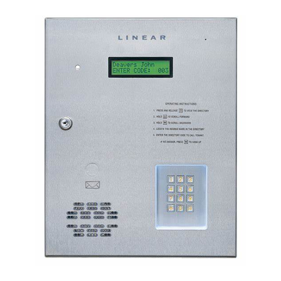
In a typical installation, the unit’s memory would be programmed with each resident’s name and directory code number. Arriving visitors would use the keypad on the AE-1000 to view the directory names and directory number for the desired resident. Upon entering the directory number, the AE-1000 will automatically dial the resident’s telephone... -
Page 3: Hardware Features
✓ 2-4 DIGIT DIRECTORY NUMBER LENGTH Directory number lengths can be customized for small or large installations ✓ LARGE TRANSMITTER CAPACITY Up to 45,600 block coded and 20,000 individually enrolled Linear transmitters can be used for gaining access ✓ TRANSMITTER FACILITY CODE SUPPORT Identifi... -
Page 4: Accessory Overview
AM-WOR WIEGAND Wiegand Accessories OUTPUT RECEIVER Two Linear accessories are available to connect WIEGAND format devices to the AE-1000. Most other manufacturer’s 26, 30 & 31-bit WIEGAND output devices can also be used with the AE-1000. AM-PR PROXIMITY READER AM-CRI... -
Page 5: Component Locations
CAN BE UN-PLUGGED FROM THE CIRCUIT BOARD CAMERA CONNECTOR TAMPER SWITCH VIDEO CONNECTOR WIEGAND INPUT TERMINALS PBUS TERMINALS NETWORK TERMINALS AM-MIO INTERFACE TELEPHONE INTERFACE TELEPHONE CONNECTOR TELEPHONE TERMINALS KEYPAD LIGHTING TAMPER RECEIVER SWITCH RANGE KNOB CONNECTOR ANTENNA CPU/INTERFACE CONNECTOR CONNECTOR... -
Page 6: Wiring Diagram
TERMINALS DVAL PCLK NET-B NETWORK TERMINALS NET-A RS-232 TELEPHONE PORT JACK FOR LOCAL COMPUTER CONNECTION NOTE: OPTIONAL USE LINEAR MODEL A2C BACKUP BATTERY SERIAL COMPUTER CABLE WILL REQUIRE AN EXTERNAL CHARGER N.C. RELAY N.O. CHANNEL "A" DS-A TERMINALS RTE-A N.C. -
Page 7: Important Mounting Requirements
Mounting Location If the AE-1000 is used to control a door or pedestrian gate, locate the unit as near as practical to the entry point. If the unit is mounted on or in a wall adjacent to the entry point, be sure the wall is sturdy. -
Page 8: Entry System Mounting
Entry System Mounting The AE-1000 cabinet is designed to be mounted three ways: • The unit can be mounted directly to a wall or fl at surface. • The unit can be mounted recessed into the wall. • The unit can be mounted on a standard gooseneck pedestal. -
Page 9: Entry System Mounting (Continued)
Be sure to replace the green ground wire. Pedestal Mounting The cabinet can be mounted on a gooseneck pedestal. Linear manufacturers two pedestals: Model GNC-1 is for surface mounting with concrete fasteners, Model GNB-1 is for burial mounting. When mounting to a pedestal, use the cabinet reinforcing plate to stiffen the cabinet. -
Page 10: Relay Output Wiring
Connect one wire to the remaining wire of the locking device. Connect the other wire to the remaining wire of the power supply. 5A. For a door strike, connect the wires to the AE-1000 relay COM & N.O. terminals. 5B. For a magnetic lock, connect the wires to the AE-1000 relay COM &... -
Page 11: Power, Battery, & Ground Wiring
AE-1000 AC1 & AC2 terminals. Backup Battery / Uninterruptable Power Supply Use of battery backup is optional. It will allow the AE-1000 to operate for short periods of time without AC power. The door or gate access device must use some type of battery backup of its own for the entire system to be functional. -
Page 12: Telephone Wiring
If wireless transmitters are going to be used in the system a remote antenna must be installed to provide reception for the AE-1000. A basic antenna kit is supplied with the AE-1000. The kit contains a whip antenna, connector, and a 36” length of coax cable. The antenna connector should be mounted on a metal surface using a 3/8”... -
Page 13: Optional Postal Lock
Optional Postal Lock A postal lock can be installed in the AE-1000 Entry System to provide keyed access for the postal service. The AE-1000 case is designed to accept a U.S. Postal Service postal lock. When the postal lock is engaged, the programmed output relay will activate. -
Page 14: Pbus Accessories
• For wire runs up to 500 feet use 20 AWG Weico Type 9405 or equivalent. 3. Connect the cable to the accessory and the AE-1000 as shown in the fi gure. NOTE: UP TO SIX PBUS DEVICES MAY BE CONNECTED... -
Page 15: Optional Network Connection
Optional Network Connection Linear’s AE-1000, AE-2000, & AM-3 Access Control Systems can be connected together in a network. A network will allow sharing programming and user information between the systems. Network wiring conforms to 3-wire RS-485 electrical specifi cations. Units connected in the network can be wired using one unit as a “hub”... -
Page 16: System Adjustments
NO SYSTEM INFORMATION WILL BE ERASED. System Diagnostics Several components on the main circuit board are for monitoring the system during operation. When calling for technical assistance, Linear’s Technical Services Department may ask the installer to use these components to diagnose the system. -
Page 17: Internal Controls
The master node must be set to 1 (default). STATUS/PROGRAM "UP" DISPLAY BUTTON "ENTER" BUTTON AE-1000 MAIN CIRCUIT BOARD SYSTEM IDLE STATUS/PROGRAM RIGHT DIGIT SHOWS NETWORK NODE ADDRESS LEFT DIGIT CIRCULATES STATUS MODE DIGITS SHOW SUPERVISORY CODE... -
Page 18: Ae-1000 Operation
• If the Anti-passback feature is enabled, the entry code will be unusable until the anti-passback time expires. Requesting Access with a Wireless Transmitter • Activate a wireless transmitter within radio range of the AE-1000’s antenna. • After a valid transmitter is decoded, and if the conditions for granting access are fulfi... -
Page 19: Specifi Cations
RADIO Frequency: 318 MHz ± 500 KHz @ 23°C Bandwidth: 300 KHz Typical Sensitivity: -97 dBm Minimum (-100 dBm Typical) Encoding: Linear MegaCode ® Format ENVIRONMENTAL Temperature: -22°F to 149°F (-30°C to 65°C) Humidity: 5% to 95% non-condensing Dimension Drawing AE-1000 13"... -
Page 20: Troubleshooting
1. Check antenna installation and condition if transmitters were previously working well. 2. Check the RADIO indicator on the AE-1000 circuit board. If it is fl ickering without activating any transmitters there is interference blocking the receiver. Try adjusting the RECEIVER RANGE knob to reduce the receiver’s sensitivity to the interference.