LG WM2277H series Training Manual
Hide thumbs
Also See for WM2277H series:
- Service manual (50 pages) ,
- Owner's manual (48 pages) ,
- Specifications (2 pages)
Table of Contents
Advertisement
Quick Links
Advertisement
Table of Contents

Related Manuals for LG WM2277H series


Summary of Contents for LG WM2277H series
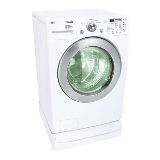
- Page 1 LG TRAINING MANUAL LG TRAINING MANUAL WM2277H* Washing Machine - Fall 2007...
-
Page 2: Table Of Contents
Safety Notices and Cautions Contents Introduction Features HE Detergent Instructions Serial Number Information Fuzzy Logic Door Lock and Door Lock Lamp Water Circulation (some versions) Parts Identification Accessories Installation Shipping Bolts Leveling Legs Pedestal Kit Connections (Water, Drain, Electricity) Control Panel Option Buttons and Option Chart Control Panel (Full explanation of all controls) Program (Cycle) Chart... - Page 3 Fault Diagnosis and Troubleshooting Checklists No Power Vibration and Spin No Water Supply No Detergent No Softener or Bleach Heater Operation Without Water (pressure sensor issue) Drain Malfunction Heater Malfunction Heater Overrun (continuous overheating) No Water Circulation (some models) Spin Malfunction Disassembly and Repair Block Wiring Diagram and Main Board Control Panel...
-
Page 4: Introduction
INTRODUCTION The WM2277** washer is most notable in that there are two distinct versions with this same model number. The only way to tell them apart is by date code, which is included in the serial number. (See page 7 concerning serial numbers.) Models with a date code of 608 or later are the newer model (without the recirculation pump);... -
Page 5: Features
FEATURES LARGE CAPACITY The larger drum (3.83 cu. ft. I.E.C.) allows washing of larger (heavier) loads and oversized items (comforters, curtains, blankets, etc.) There is less wrinkling and tangling of the laundry. DIRECT DRIVE The brushless DC motor drives the drum directly without belts, pulleys, or transmissions. - Page 6 FEATURES, continued BUILT-IN HEATER The internal heater helps maintain the water at its optimal temperature for selected cycles. The SANITARY cycle kills most common germs and bacteria. CHILD LOCK This allows the user to lock the controls. Children then cannot play with the buttons and disturb the wash cycle.
-
Page 7: Serial Number Information
SERIAL NUMBER INFORMATION The serial number is unique to each product. It gives information concerning the time and place of manufacture. The serial number is required to be paid for warranty service and to get the correct part in the event a running production change was made. -
Page 8: Fuzzy Logic
FUZZY LOGIC To get the best washing performance, the user selects one of the standard cycles. Sensors in the washer allow the microprocessor to make an infinitely variable number of adjustments as the cycle progresses. Adjustments are made automatically for load size, incoming water temperature, soil level, rinses required, and other variables. -
Page 9: Water Circulation (Some Versions)
WATER CIRCULATION (Some Versions) On earlier versions of the WM2277, the recirculation pump circulates the water during most of the cycle. Later versions do not include the recirculation pump. During the WASH cycle, the pump runs continuously for the first 3 minutes and then intermittently throughout the cycle. -
Page 10: Parts Identification
PARTS IDENTIFICATION (Front of Washer) (Back of washer) WM2277 WASHER PAGE 12 of 84 TRAINING MANUAL... -
Page 11: Accessories
The air vent on the back of the machine must be left open and clear at all times. If the washer is installed in a closet or closed laundry alcove, there must be sufficient clearance and ventilation. The closet should have a full louvered door with at least 800 square inches (0.5 m ) of open area for ventilation. -
Page 12: Installation
INSTALLATION Unpack the washer near the installation area. Cut the straps and lift off the box. Check the packing materials for manuals and accessories before discarding them. Notice the wrench packed in the foam shipping base. This will be used to level the legs and to remove the shipping bolts. - Page 13 Remove the shipping bolts when you get the washer into the utility room and not before. Save the bolts in case the washer must be moved for servicing or relocation. Notice that one of the bolts has a retainer clip for securing the cord. This is another way to encourage the removal of the shipping bolts.
- Page 14 INSTALL THE WASHER ON A FIRM, FLAT SURFACE. ADJUST THE FEET TO BE LEVEL. This photo shows the leveling leg with plastic foot and locking ring. After adjusting the foot by using the wrench to raise or lower it. You can lock the adjustment into place by tightening the lock ring against the underside of the washer.
-
Page 15: Pedestal Kit
INSTALLATION (PEDESTAL KIT) This procedure covers installing and leveling the 7½” and 13” pedestals for 27” washers, dryers, and combos. If the products are stacked, the washer must be below the dryer, and you’ll use only one pedestal. Remove the pedestal, installation hardware, and instructions form the shipping carton. - Page 16 PEDESTAL, continued Depending upon the model, your pedestal may have straight or curved brackets. The curved ones are to be used on the rear positions when mounting a dryer to a pedestal, but can also be used in any other position on the pedestal.
-
Page 17: Connections (Water, Drain, Electricity)
CONNECTIONS WATER Be sure the rubber washer is inside the hose end. Attach the hoses to the washer (red is HOT, blue is COLD). Tighten them firmly but don’t strip the plastic threads on the washer connections. Be sure to use the correct hoses for and COLD. -
Page 18: Control Panel
CONTROL PANEL The control panel is located on the front of the washer. All options are available from the control panel. (See larger drawing, page 20.) The large knob that selects the cycle. (See chart, p. 21.) Cycle Knob Pressing this button turns the machine ON or OFF. ON/OFF button START/PAUSE Press this button to start the cycle or to pause the... -
Page 19: Option Buttons
OPTION BUTTONS PRE-WASH Press to add a pre-wash cycle. * Child Lock (Press and hold to select or deselect the Child Lock function) RINSE+SPIN Press after power-up without selecting a cycle to RINSE and SPIN only, without washing! EXTRA RINSE Press to add an EXTRA RINSE cycle. - Page 20 WM2277** Control Panel (New Version) WM2277 WASHER PAGE 22 of 84 TRAINING MANUAL...
-
Page 21: Program (Cycle) Chart
PROGRAM CHART This chart shows the components and their times of operation in the various wash cycles. The time estimates shown here are for the basic cycles before the fuzzy logic adjustments are made. Variations may be made in almost any cycle by making adjustments on the control panel. -
Page 22: Dispenser
DISPENSER The dispenser drawer is a multi-chambered reservoir that allows the user to add all the appropriate laundry additives before starting the cycle. It has a place for pre-wash detergent, main wash detergent, fabric softener, and bleach. Powdered or liquid detergents may be used, but softener and bleach must be liquids. Detergents must carry the HE designation. - Page 23 The dispenser works by using various solenoids to apply water to different compartments. The liquid products are dispensed from a siphon box. As the appropriate chamber is flooded, the box fills and the water flushes the laundry product into the tub. It is mixed with water before contacting the laundry to prevent spotting or damaging the fabric.
-
Page 24: Direct Drive Motor
DIRECT DRIVE MOTOR The motor is a direct-drive, brushless, DC motor. It is attached to the drum via a splined shaft, eliminating belts, pulleys, transmissions, and the inherent problems associated with them. The rotor is attached to the shaft by one large (17 mm) bolt. -
Page 25: Hall Effect Sensor
HALL EFFECT SENSOR The Hall Effect sensor is easily removed and replaced. You’ll have to remove the rotor and stator to access the sensor. When replacing the rotor, you’ll probably need a helper to hold the drum in place when you push the rotor onto the shaft. -
Page 26: Hall Effect Sensor Test Procedure
HALL SENSOR TEST PROCEDURE Check the wiring diagram for your machine. The wiring diagrams on some washing machines were incorrect in depicting the hall sensor wiring. The error involves wiring terminal designation. See the diagrams below. The correct wiring terminal colors are: White is (+) Gray is (-) Red is Hb... - Page 27 Hall Sensor testing methods are now available on the following pages when LE error code troubleshooting says “hall sensor is out of order or defective.” Test FIRST!! 1 – BL (Ha) 2 – RD (Hb) 3 – Not Used 4 – GRY (-) Magnetic Pickups &...
- Page 28 Hall Sensor Testing The hall sensor can be tested from the control board or at the hall sensor. Ohm Testing the Hall Sensor If tested off the stator using the diagram on the previous page, ohm check the resistors from pin 5 to pin 1 and pin 2.
- Page 29 Testing the Hall Sensor from the Control Board Control Board Testing Location Control Board Output and Hall Sensor Input can be measured with the connector connected to the board and the machine operating. Also, these voltages can be measured by parking the meter leads on the desired terminals and spinning the tub briskly with the power cord disconnected.
- Page 30 LG Electronics. Unauthorized modifications will not only void the warranty, but may lead to property damage or user injury. If wires, screws, clips, straps, nuts, or washers used to complete a ground path are removed for service, they must be returned to their original positions and properly fastened.
- Page 31 Actual Terminal Wiring The potting epoxy has been removed to show the PC board and components. Voltage Testing Hall Sensor at Control Board (See page 29.) 1. Unplug the power cord. 2. Remove the rear panel. 3. Remove the top plate. 4.
-
Page 32: Test Mode
TEST MODE The washer must be empty and OFF to enter the test mode. 1. Press and hold SPIN SPEED and SOIL LEVEL. 2. Press POWER. 3. Press START/PAUSE to cycle through the test modes. (See chart.) # of times Event Display the START button... -
Page 33: Error Display
ERROR DISPLAY • If you press START/PAUSE when an error is displayed, any error (except PE) will disappear and the machine will enter PAUSE mode. • In the event of PE, tE, or dE, The power will be turned off within 20 seconds and the error code will blink. - Page 34 ERROR DISPLAY, continued WM2277 WASHER PAGE 35 of 84 TRAINING MANUAL...
- Page 35 DIAGNOSIS and CHECK LIST (Abnormal Operation) WM2277 WASHER PAGE 36 of 84 TRAINING MANUAL...
-
Page 36: Diagnosis And Check List
DIAGNOSIS and CHECK LIST (Abnormal Operation, continued) WM2277 WASHER PAGE 37 of 84 TRAINING MANUAL... - Page 37 DIAGNOSIS and CHECK LIST (Abnormal Operation, continued) WM2277 WASHER PAGE 38 of 84 TRAINING MANUAL...
-
Page 38: Fault Diagnosis And Troubleshooting Checklists
FAULT DIAGNOSIS and TROUBLESHOOTING WM2277 WASHER PAGE 39 of 84 TRAINING MANUAL... - Page 39 DIAGNOSIS/TROUBLESHOOOTING (continued) WM2277 WASHER PAGE 40 of 84 TRAINING MANUAL...
-
Page 40: No Water Supply
DIAGNOSIS/TROUBLESHOOOTING (continued) NO WATER SUPPLY DETERGENT NOT DISPENSED WM2277 WASHER PAGE 41 of 84 TRAINING MANUAL... - Page 41 DIAGNOSIS/TROUBLESHOOOTING (continued) LIQUID SOFTENER AND BLEACH ARE NOT DISPENSED WM2277 WASHER PAGE 42 of 84 TRAINING MANUAL...
- Page 42 DIAGNOSIS/TROUBLESHOOOTING (continued) WM2277 WASHER PAGE 43 of 84 TRAINING MANUAL...
-
Page 43: Heater Malfunction
DIAGNOSIS/TROUBLESHOOOTING (continued) HEATER MALFUNCTION (CONTINUOUS OVERHEATING) WM2277 WASHER PAGE 44 of 84 TRAINING MANUAL... - Page 44 DIAGNOSIS/TROUBLESHOOOTING (continued) Before conducting this diagnostic procedure, be sure your version includes the recirculation pump. The pump housings are not interchangeable, and this option cannot be added to a version not so equipped at the factory. WM2277 WASHER PAGE 45 of 84 TRAINING MANUAL...
- Page 45 DIAGNOSIS/TROUBLESHOOOTING (continued) WM2277 WASHER PAGE 46 of 84 TRAINING MANUAL...
-
Page 46: Disassembly And Repair
DISASSEMBLY and REPAIR The following pages will show the instructions for disassembly, repair, replacement of parts, and reassembly. Many times, electrical components may be tested by connecting the appropriate meter to the leads or connectors on the main PC Board. (Refer to the block wiring diagram, below.) Proper diagnosis will eliminate unnecessary labor and expedite repairs. -
Page 47: Control Panel
DISASSEMBLY/REPAIR (Control Panel) Remove two screws on the back of the top plate. Pull the top plate backward and lift, as shown. Remove the detergent drawer. Remove two screws behind the detergent drawer. Disconnect the connectors for the Display PWB. Remove one screw from the corner of the control panel. -
Page 48: Main Board
DISASSEMBLY/REPAIR (Main Board) Often, you can diagnose a failed part by removing its connector on the main board and connecting the tester to the leads in the connector. (See page 45.) Disconnect the POWER connector and the Water Level Sensor Switch. Remove the protective cover. -
Page 49: Dispenser
DISASSEMBLY/REPAIR (Dispenser) Remove the top plate. (See page 46.) Remove the dispenser drawer. Remove two screws to release the dispenser. Loosen the clamp on the large hose that runs from the dispenser to the drum. Have an old towel handy to stuff under the dispenser to soak up any spillage. -
Page 50: Front Cabinet, Tub, And Drum
DISASSEMBLY/REPAIR (Front Cabinet, Tub, and Drum) NOTE! There is a piece of adhesive foam tape along the top rail on both sides of the machine. This is to prevent noise from vibration. It may become stuck to the top, so you’ll need to use an extra push to get the top plate loose. - Page 51 Open the door. Remove the clamp using special tool 383EER4001A. Leave the gasket attached to the tub at this time. Lean the cabinet front forward, being careful to avoid breaking the glass. The door is HEAVY. Disconnect the door switch connector.
- Page 52 Use the weights you removed from the front of the tub as supports to hold the tub while you work on it and to avoid damaging the shaft and floor. Unbolt the tub halves to separate them and remove the drum.
-
Page 53: Door
DISASSEMBLY/REPAIR (Door) Removing the door with the front cover still on the machine. Open the door. Remove seven screws from the hinge cover. Pry off the hinge cover with a flat screwdriver. Remove the screw at the bottom of the hinge. Lift the door off the hinge. - Page 54 DISASSEMBLY/REPAIR (Pump) Remove the front cabinet. (See page 46.) Drain the water from the sump. (See page 9.) Remove the clamps and hoses. Remove two screws and push the pump backward and up. Press down the plastic tab on the base behind the pump to slide the pump assembly backward.
-
Page 55: Pump(S)
DRAIN PUMP (Your model may vary) Before performing this operation, verify which version WM2277 you are repairing. Some do not have the recirculation pump. The drain pump and the circulating pump are attached to either side of the filter housing. The pumps are different and are not interchangeable. The drain pump is used to exhaust the water from the washer. -
Page 56: Heater
DISASSEMBLY/REPAIR (Heater) Remove the front cabinet. (See page 46.) Drain the water from the sump. (See page 9.) Remove the push-on connectors from the heater. Remove the nut that holds the ground wire. Then loosen but do not remove the nut that secures the heater clamp and pull the heater out. - Page 57 DISASSEMBLY/REPAIR (Object between tub and drum) Remove the top cover. (See page 46.) Remove the front cabinet cover. (See page 48.) Remove the heater. (See page 55.) Fish out the foreign object(s) using a wire or bar. WM2277 WASHER PAGE 58 of 84 TRAINING MANUAL...
-
Page 58: Motor
DISASSEMBLY/REPAIR (Motor) For technical information concerning the direct drive DC motor, refer to page 25.) Remove the back cover. Remove the large bolt in the center shaft. (Your helper can hold the inside of the drum.) Pull the rotor off the shaft. Remove two screws from the tub bracket. - Page 59 DISASSEMBLY/REPAIR (Damper) Disconnect the dampers from the tub and the base. (See photos, left.) Be sure to press in the safety tab before pushing the pin out of the damper. You can use a socket to hold the tab in while you squeeze the pin with the special tool 383EER4003A.
-
Page 60: Water Level Switch
WATER LEVEL SWITCH The water level detector switch monitors the water level and feeds this information to the MICOM. The sensor reads air pressure in an air chamber on the tub. The air pressure changes in relation to the depth of the water, moving a diaphragm in the switch. -
Page 61: Tips And Tricks
TIPS and TRICKS HOSES When replacing the large hoses, be sure to avoid getting the lip turned under the hose clamp. This will damage the hose and cause a leak. The large hoses have notches on the ends to index them on the connectors. Be sure the notch is pushed down all the way on the index boss. -
Page 62: Draining The Sump
MAIN BOARD The main board must be replaced if defective; it is not repairable. This diagram is shown to point you to the various connectors that can be removed or used as test points. Testing at the connectors will allow the servicer to make a more complete diagnosis and eliminate some of the time required to disassemble and check various components. -
Page 63: Exploded View
EXPLODED VIEW WM2277 WASHER PAGE 64 of 84 TRAINING MANUAL... - Page 64 EXPLODED VIEW WM2277 WASHER PAGE 65 of 84 TRAINING MANUAL...
- Page 65 EXPLODED VIEW WM2277 WASHER PAGE 66 of 84 TRAINING MANUAL...
-
Page 66: Parts List
PARTS LIST This parts list is included with part numbers for the newer (Date Code 608 and later) version of WM2677. For part numbers for the earlier version, see the original service manual and the service bulletins included in this training manual. Loc # Part No Description... - Page 67 Loc # Part No Description A430 6411ER1005K Power Cord Assembly A440 6601ER1004C Switch Assembly, Locker A450 6871ER1078T PCB Assembly, Main A455 3550ER1032A Cover, Protective (Main Board) A485 6201EC1006A Filter Assembly, Noise F110 6871ER2078A PCB Assembly, Display F120 6877ER1044G Harness, Multi F130 6850ER2003B Wire, Flat...
- Page 68 Loc # Part No Description F466 ------------------- Clamp (local hardware item) F467 4860FR3092C Clamp F468 ------------------- Clamp (local hardware item) K105 3045ER0008N Tub Assembly, Outer (Back half) K110 3045ER1006E Drum Assembly (Inner) K111 4433ER1003A Lifter Assembly (Baffle) K115 4434ER0002A Spider K121 4280FR4048L Bearing, Ball...
- Page 69 Loc # Part No Description ------- 3W20018B Wrench ------- 383EER4001A Gasket Pliers, Outer (SPECIAL TOOL) ------- 383EER4003A Damper Pliers (SPECIAL TOOL) ------- 383EER4004A Gasket Pliers, Inner (SPECIAL TOOL) ------- 5241FR3018D Drain Hose Extension (5 FEET) ------- 4769ER4002A Mushroom valve (fill tube) (not pictured) ------- 4769ER4001A Mushroom valve (vent tube) (not pictured)
-
Page 70: Service Bulletins
SERVICE BULLETINS LG issues service bulletins as products are improved and for many other reasons. The bulletins available at the time this manual was printed are included. Updated materials, including this training manual, service manuals, owner’s manuals, specifications, and other items are available online at LG’s GCSC (Global Cyber Service Center) and via LGCSAcademy. - Page 71 WM2277 WASHER PAGE 72 of 84 TRAINING MANUAL...
- Page 72 WM2277 WASHER PAGE 73 of 84 TRAINING MANUAL...
- Page 73 WM2277 WASHER PAGE 74 of 84 TRAINING MANUAL...
- Page 74 WM2277 WASHER PAGE 75 of 84 TRAINING MANUAL...
- Page 75 WM2277 WASHER PAGE 76 of 84 TRAINING MANUAL...
- Page 76 WM2277 WASHER PAGE 77 of 84 TRAINING MANUAL...
- Page 77 WM2277 WASHER PAGE 78 of 84 TRAINING MANUAL...
- Page 78 WM2277 WASHER PAGE 79 of 84 TRAINING MANUAL...
- Page 79 WM2277 WASHER PAGE 80 of 84 TRAINING MANUAL...
- Page 80 WM2277 WASHER PAGE 81 of 84 TRAINING MANUAL...
- Page 81 WM2277 WASHER PAGE 82 of 84 TRAINING MANUAL...
- Page 82 2007 WM2277H* Washer Training...