
Related Manuals for LevelOne FCS-3083


Summary of Contents for LevelOne FCS-3083
- Page 1 Fixed Dome Network Camera Hardware User Manual FCS-3055, FCS-3082, FCS-3083 Ver.2014/01/15...
-
Page 2: Table Of Contents
Hardware Manual Table of Contents Precautions ............... 4 Safety Instructions ....................6 Introduction ..............7 The List of Models ....................7 Ou Package Contents ....................8 Physical Description ....................9 Installing the Camera on a Surface ......11 Step 1: Drill the Holes .................... 11 Step 2: Open the Dome Cover ................ - Page 3 Hardware Manual Other Adjustments and Accessories ......30 How to Adjust the Viewing Angle ................ 30 FCS-3055 / FCS-3082 / FCS-3083 ............30 How to Install / Remove the Memory Card............31 How to Insert the Memory Card ............31 How to Remove the Memory Card ............
-
Page 4: Precautions
Hardware Manual Precautions Read these instructions You should read all the safety and operating instructions before using this product. Heed all warnings You must adhere to all the warnings on the product and in the instruction manual. Failure to follow the safety instruction given may directly endanger people, cause damage to the system or to other equipment. - Page 5 Hardware Manual Federal Communications Commission Statement This equipment has been tested and found to comply with the limits for a class B digital device, pursuant to Part 15 of the FCC Rules. These limits are designed to provide reasonable protection against harmful interference in a residential installation.
-
Page 6: Safety Instructions
Hardware Manual Safety Instructions Cleaning Disconnect this video product from the power supply before cleaning. Attachments Do not use attachments not recommended by the video product manufacturer as they may cause hazards. Do not use accessories not recommended by the manufacturer Only install this device in a dry place protected from weather Servicing Do not attempt to service this video product yourself. -
Page 7: Introduction
Fixed Dome Network Camera, 3-Megapixel, Outdoor, PoE 802.3af, Day FCS-3082 & Night, IR LEDs, WDR Fixed Dome Network Camera, 5-Megapixel, Outdoor, PoE 802.3af, Day FCS-3083 & Night, IR LEDs, WDR From the installation perspective, these models are similar; therefore, one manual is used for all of them. -
Page 8: Ou Package Contents
Hardware Manual Package Contents Camera Mounting Screw Kit Hexagon Screwdriver Drill Template Conduit Gland Cable Gland Drill Template Lens Focus Tuner Terminal Block Quick Installation Guide (for D7xA / E7xA only) (for Audio and DI/DO) -
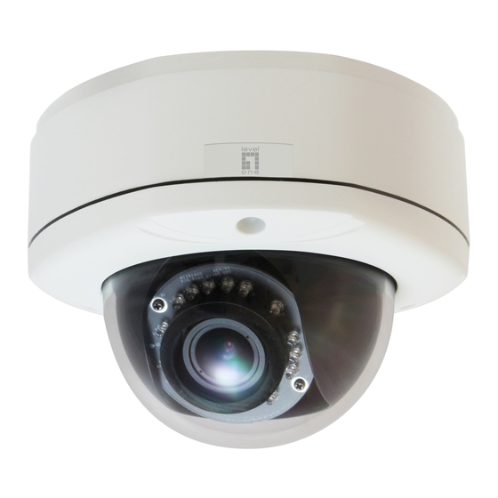
Page 9: Physical Description
Hardware Manual Physical Description NOTE: The camera picture above is for reference only. Actual camera may slightly differ. 1) Ethernet Port Connects to a network using an Ethernet cable. 2) Memory Card Slot Insert a memory card (not included) into this slot for local recording purposes. See How to Install / Remove the Memory Card on page 31 for more information. - Page 10 Hardware Manual 4) Digital Input / Output (DI/DO) and Audio Input / Output This connector connects to digital input or output devices, such as an alarm trigger, panic button, etc., as well as audio input and output devices, such as microphones and speakers. Digital Input (DI) and Digital Output (DO) devices are used in applications like motion detection, event triggering, alarm notifications, etc.
-
Page 11: Installing The Camera On A Surface
Hardware Manual Installing the Camera on a Surface This section describes the procedures in installing the camera on a flat surface such as a hard or dropped ceiling and straight or tilted walls. Before installation, make sure the wall or ceiling can bear more than the weight of the camera. -
Page 12: Step 2: Open The Dome Cover
Hardware Manual Step 2: Open the Dome Cover NOTE: To avoid scratches or leaving fingerprints on the dome cover, it is recommended to retain the plastic covering the dome cover until the camera is completely installed. However, the plastic has been removed on the pictures in this documentation to show clarity of the procedures being described. - Page 13 Hardware Manual 3. Carefully lift to open the dome cover and place it on the side of the camera. NOTE: Do not abruptly lift the dome cover; it is attached to the camera with a spring wire. 4. If necessary, insert a memory card with the metallic contacts facing down into the card slot of the camera.
-
Page 14: Step 3: Prepare For Waterproof Installation
Hardware Manual Step 3: Prepare for Waterproof Installation The camera comes with two (2) glands used for waterproof installation: Cable Gland: For use with an Exterior-grade Ethernet cable. Exterior-grade Ethernet cables are already waterproof. See Waterproof Solution with Naked Cable on page ... -
Page 15: Waterproof Solution With Naked Cable
Hardware Manual Waterproof Solution with Naked Cable This section describes the procedures in using the bundled cable gland and an exterior-grade Ethernet cable. 1. Disassemble the cable gland as shown below: Sealing Insert Body Clamping with Claw (with Washer) 2. Insert the clamping nut into the Ethernet cable. 3. - Page 16 Hardware Manual 4. Attach the cable gland body to the hole of the camera. Attach to Camera Side Hole Attach to Camera Bottom Hole 5. If the cable will be routed along the surface, skip this step. If the cable will pass through the surface, do the following: a.
-
Page 17: Waterproof Solution With Conduit
Hardware Manual Waterproof Solution with Conduit This section describes the procedures to waterproof the cabling connections using the bundled conduit gland and flexible conduit. This is the recommended if other input/output devices or an external power adapter will be connected to the camera or when an exterior-grade Ethernet cable is not available. - Page 18 Hardware Manual 3. Pull the network cable through the flex conduit. If connecting other input/output devices or an external power adapter, pull the cables through the flex conduit without connectors. The terminal blocks will be attached once the cables pass through the camera hole later. 4.
- Page 19 Hardware Manual 6. Screw the conduit gland body to the conduit hole of the camera. Attach to Side Conduit Hole Attach to Bottom Conduit Hole 7. If the cables will be routed along the surface, skip this step. If the cables will pass through the surface, do the following: a.
- Page 20 Hardware Manual 8. If connecting other cables, attach the terminal blocks to the cables. See Other Connections on page 25. 9. Proceed with Step 4: Install the Camera to the Surface on page 21.
-
Page 21: Step 4: Install The Camera To The Surface
Since electric screwdrivers vary in sizes, speed, and force, they may bruise and damage the internal camera components. DISCLAIMER: LevelOne will not be responsible for camera damage caused by improper installations or the misuse of equipment for installation. -
Page 22: Step 5: Connect The Cable(S)
Hardware Manual Step 5: Connect the Cable(s) 1. If the cables will be routed along the surface, pull the network cable and other cables (if any) through the side conduit hole and attach the sealing insert and the clamping nut to the gland body. -
Page 23: Step 6: Access The Camera Live View
Hardware Manual 3. Connect the other end of the network cable to a switch or injector. Then, connect the switch or injector to a network or PC and a power source. See Power-over-Ethernet (PoE) example connection diagram below. Network Ethernet Cable Ethernet Cable (Data) PoE Injector /... -
Page 24: Step 8: Close The Dome Cover
Hardware Manual Step 8: Close the Dome Cover 1. Align the position of the dome cover shroud to the direction of the lens. 2. Tighten the three (3) screws to attach the dome cover to the camera body. 3. Remove the plastic covering the dome cover. Final installation will look like the illustration below. -
Page 25: Other Connections
Hardware Manual Other Connections This section describes the procedures in preparing the Digital Input and Output (DI/DO) and Audio Input and Output devices that you can connect to the camera using the bundled terminal blocks. The use of these devices, however, is optional. Connecting DI/DO and Audio Devices (Optional) Depending on your surveillance needs, you may connect digital input / output or audio input / output devices to your camera. - Page 26 Hardware Manual Press and hold the orange tab as you insert the wire through the pin slot, then release the orange tab to secure the wire. For Audio Use To connect digital input / output devices (DI/DO), map the pins to one of the pin combinations below: Device Mapping Instructions...
- Page 27 Hardware Manual Typical Connection Based on these specifications, if the DI device has a voltage of 0V ~ 30V or the DO device has a voltage of < 24V (< 50mA), then the camera can supply internal power to these devices and there is no need to connect the DI/DO device to an external power source.
- Page 28 Hardware Manual The illustration below is a graphic example of connecting a relay to a high voltage DO device. 110V-220V AC External Power Source Relay (DO1 Device) Camera Illuminator NOTE: For more information on DI/DO connections, please refer to the Knowledge Base article on our website.
-
Page 29: How To Connect Audio Devices
Hardware Manual How to Connect Audio Devices Audio input / output devices, such as an active microphone or speaker can be connected to the camera using the supplied terminal block. Press and hold the orange tab as you insert the wire through the pin slot, then release the orange tab to secure the wire. -
Page 30: Other Adjustments And Accessories
How to Adjust the Viewing Angle This section describes the procedures in adjusting the viewing angle and pan direction of the camera. FCS-3055 / FCS-3082 / FCS-3083 Camera Parts Overview Adjustment Procedures 1. Loosen the tilt adjustment screws, adjust the tilt, and then tighten back the screws to fix... -
Page 31: How To Install / Remove The Memory Card
Hardware Manual 2. Move the rotation adjustment to rotate the viewing orientation. 3. Loosen the pan adjustment screw, move the pan direction, and then tighten back the screw to fix the pan position. 4. If necessary, loosen the zoom and focus lever screws, then move the zoom and focus levers left or right to adjust the focus and the viewing angle. -
Page 32: How To Replace The Dome Cover
Hardware Manual How to Replace the Dome Cover For more discrete surveillance needs, the bundled dome cover can be replaced with a smoke, vandal proof cover available for purchase. To replace the dome cover, do the following: 1. Loosen the three (3) screws to open the dome cover. 2. - Page 33 Hardware Manual 4. Remove dome cover from the cover housing. 5. Remove the shroud from the dome cover. 6. Insert the shroud into the replacement dome cover. 7. Insert the replacement dome cover into the cover housing.
- Page 34 Hardware Manual 8. Align and attach the three (3) screws to secure the bracket to the cover housing. 9. Fit the screw into the spring wire that is attached to the camera. 10. Attach the screw to the dome cover using a screwdriver. Final installation should look like the illustration below.
-
Page 35: Accessing The Camera
Hardware Manual Accessing the Camera Configure the IP Addresses In order to be able to communicate with the camera from your PC, both the camera and the PC have to be within the same network segment. In most cases, it means that they both should have very similar IP addresses, where only the last number of the IP address is different from each other. - Page 36 Hardware Manual Double-click the mouse button on the camera model name, the default browser of the PC is automatically launched and the IP address of the target camera is already filled in the address bar of the browser. If you work with our cameras regularly, then there is even a better way to discover the cameras in the network –...
- Page 37 Hardware Manual Use the default IP address of a camera: If there is no DHCP server in the given network, the user may have to assign the IP addresses to both PC and camera manually to make sure they are in the same network segment. When the camera is plugged into network and it does not detect any DHCP services, it will automatically assign itself a default IP: 192.168.0.100...
- Page 38 Hardware Manual Manually adjust the IP addresses of multiple cameras: If there are more than 1 camera to be used in the same local area network and there is no DHCP server to assign unique IP addresses to each of them, all of the cameras would then have the initial IP address of 192.168.0.100, which is not a proper situation for network devices –...
-
Page 39: Access The Camera
Hardware Manual Access the Camera Now that the camera and the PC are both having their unique IP addresses and are under the same network segment, it is possible to use the Web browser of the PC to access the camera. You can use any of the browsers to access the camera, however, the full functionality is provided only for Microsoft Internet Explorer. - Page 40 Hardware Manual Assuming that the camera’s IP address is 192.168.0.100, you can access it by opening the Web browser and typing the following address into Web browser’s address bar: http://192.168.0.100 Upon successful connection to the camera, the user interface called Web Configurator would appear together with the login page.
- Page 41 To check the firmware version through the Web Configurator, access the Setup page and click System > System Info. For further operations, please refer to the Firmware User Manual.