Advertisement
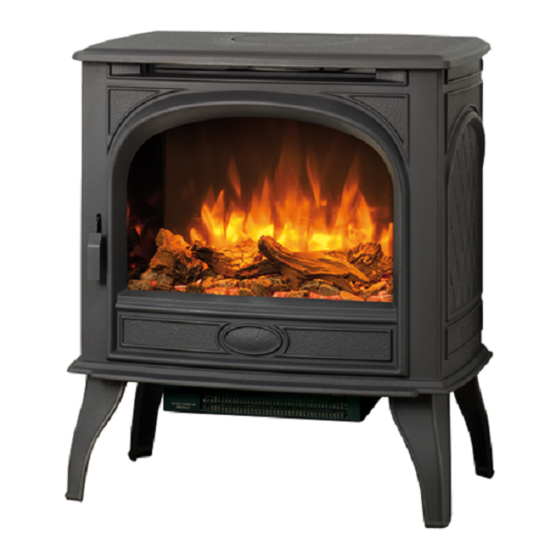
Dovre 425
Conventional Flue Log Effect Stove
With Upgradeable Control Valve
Instructions for Use, Installation and Servicing
For use in GB, IE (Great Britain and Republic of Ireland)
IMPORTANT
THE OUTER CASING, FRONT AND GLASS PANEL BECOME EXTREMELY HOT DURING OPERATION AND
WILL RESULT IN SERIOUS INJURY AND BURNS IF TOUCHED. IT IS THEREFORE RECOMMENDED THAT A
FIREGUARD COMPLYING WITH BS 8423:2002 IS USED IN THE PRESENCE OF YOUNG CHILDREN, THE
ELDERLY OR INFIRM.
This product contains a heat resistant glass panel. This panel should be checked during Installation and at each servicing interval. If any
damage is observed on the front face of the glass panel (scratches, scores, cracks or other surface defects), the glass panel must be
replaced and the appliance must not be used until a replacement is installed. Under no circumstances should the appliance be used if any
damage is observed, the glass panel is removed or broken.
It is essential that ALL of the screws that retain the glass frame are replaced and tightened correctly. Under no circumstances should the
appliance be operated if any of these screws are loose or missing.
These Instructions must be left with the appliance for future reference and for consultation when servicing the appliance. Please make the
customer aware of the correct operation of the appliance before leaving these instructions with them.
The commissioning sheet found on Page 3 of this Instruction manual must be completed by the Installer prior to leaving the premises.
PR0986 Issue 4 (October 2014)
Advertisement
Table of Contents

Related Manuals for Dovre 425


Summary of Contents for Dovre 425
- Page 1 Dovre 425 Conventional Flue Log Effect Stove With Upgradeable Control Valve Instructions for Use, Installation and Servicing For use in GB, IE (Great Britain and Republic of Ireland) IMPORTANT THE OUTER CASING, FRONT AND GLASS PANEL BECOME EXTREMELY HOT DURING OPERATION AND WILL RESULT IN SERIOUS INJURY AND BURNS IF TOUCHED.
-
Page 2: Table Of Contents
Contents Covering the following models: Model NATURAL GAS Matt Black DV-425CFNG DV-425CFLPG Ivory Enamel DV-425CFNGIV DV-425CFLPGIV Ivory White Enamel DV541-076 DV541-479 Majolica Brown DV-425CFNGMJ DV-425CFLPGMJB Black Enamel DV-425CFNGBK DV-425CFLPGBK Appliance Commissioning Checklist ......3 User Instructions ............4 Installation Instructions ..........9 Technical Specifications ............. 9 Site Requirements .............. -
Page 3: Appliance Commissioning Checklist
Appliance Commissioning Checklist To assist us in any guarantee claim please complete the following information:- IMPORTANT NOTICE Explain the operation of the appliance to the end user, hand the completed instructions to them for safe keeping, as the information will be required when making any guaranteed claims. FLUE CHECK PASS FAIL... -
Page 4: User Instructions
Congratulations on purchasing your Dovre 425 stove, if No furnishings or other objects should be placed within installed correctly Dovre hope it will give you many years of 1 metre of the front of the appliance. warmth and pleasure for which it was designed. - Page 5 REMOVING THE DOOR There is no requirement for this upgrade to be carried out by an approved Gas engineer. However Dovre recommend that For rear flue exit lift the top of the appliance off and put to this task is undertaken by a suitably competent person.
- Page 6 User Instructions Lift the front upwards until it is clear of the slots and pull 6. Arrangement of Fuel Bed away from the appliance, see Diagram 3. Advice on handling and disposal of fire ceramics The fuel effect of the log version of this appliance is made from Refractory Ceramic Fibre (RCF), a material which is commonly used for this application.
- Page 7 User Instructions Ensure there is an equal gap between each side of the log There are two ash panels which lay across the front of the and the side of the firebox. burner skin. Place the panel with the flat edge facing the left side of the firebox.
- Page 8 APPLIANCE FOR 3 MINUTES. 11. Running In 11.1 During initial use of a new Dovre appliance a strong odour will be encountered as various surface coatings become hot With the top still supported or removed refit front by locating for the first time. Although these odours are harmless it is in grooves and lowering into place, see Diagram 13.
-
Page 9: Installation Instructions
Installation Instructions Technical Specification Covering the following models: Model NATURAL GAS Matt Black DV-425CFNG DV-425CFLPG Ivory Enamel DV-425CFNGIV DV-425CFLPGIV Ivory White Enamel DV541-076 DV541-479 Majolica Brown DV-425CFNGMJ DV-425CFLPGMJB Black Enamel DV-425CFNGBK DV-425CFLPGBK Model Gas Type Working Aeration Injector Gas Rate Input kW (Gross) Country CAT. -
Page 10: Site Requirements
UK ONLY: The minimum flue height for the appliance must be 3 The Dovre 425 has a nominal input not exceeding 7.0kW metres (10ft). Any horizontal flue run from the rear outlet and does not normally require any additional permanent must not exceed 100mm from the back of the appliance. - Page 11 Installation Instructions Site Requirements 50mm In a non-combustible recess be careful to allow enough clearance at the sides and rear of the appliance to perform spillage tests and reach the controls.
-
Page 12: Installation
There is no requirement for this upgrade to be carried out by and using this appliance. an approved Gas engineer. However Dovre recommend that this task is undertaken by a suitably competent person. These instructions must be left intact with the user. - Page 13 Installation Instructions Connect the gas supply to the 8mm compression elbow at Lift the front upwards until it is clear of the slots and pull the right-hand rear corner of the appliance away from the appliance, see Diagram 3. There is a cutout in the right-hand rear leg to enable a straight connection to the rear of the appliance, see Diagram 1.
- Page 14 Installation Instructions Ensure there is an equal gap between each side of the log 6. Arrangement of Fuel Bed and the side of the firebox. Place log B on the left hand side of the burner with the Advice on handling and disposal location bar on the underside of the log fully located in the of fire ceramics long slot of the burner.
- Page 15 Installation Instructions There are two ash panels which lay across the front of the 8. Completion of Assembly burner skin. Place the panel with the flat edge facing the left side of the firebox. There are location holes on this panel which fit over the screw holes of the burner skin, see Ensure the rope seal fitted to the rear of the glass frame is Diagram 9.
-
Page 16: Commissioning
Installation Instructions/Commissioning 9. Operating the Appliance 1. Commissioning The control valve is at the foot on the right-hand side of the Close all doors and windows in the room. appliance. It has two controls, see Diagram 24: Ignite the appliance and operate on maximum for 10 1. -
Page 17: Servicing Requirements
Replacement glass panels can be Advise the customer of any remedial work undertaken. purchased from Dovre via the retailer from which the appliance was purchased or any other Dovre distributor. 7 mm... - Page 18 Servicing Instructions Fault Finding Charts...
-
Page 19: How To Replace Parts
If, for any reason, the flue has to be removed from the appliance, the seal must be replaced in the inner spigot. 2. Removing the Door IMPORTANT: THE OUTER PANELLING OF THE DOVRE 425 IS MADE FROM CAST IRON. USE CAUTION WHEN INSTALLING, REMOVING AND STORING AS THE COMPONENTS ARE HEAVY AND SHOULD BE HANDLED CAREFULLY. - Page 20 Servicing Instructions - Replacing Parts 4. Main Burner 5a Pilot Burner Bracket Refer to Section 4 to remove the main burner. Remove the three securing screws, two at the rear and one at the front left hand side, see Diagram 4. Remove the two fixing screws from the pilot bracket, see Diagram 5.
- Page 21 Servicing Instructions - Replacing Parts 5d Thermocouple 6. Ignition Lead Undo the retaining nut and withdraw the thermocouple. Undo Follow the Pilot Unit instruction to access the back of the the thermocouple from the back of the gas valve, see pilot assembly.
- Page 22 Servicing Instructions - Replacing Parts 7. Piezo 10. Main Injector The piezo assembly used on this appliance is not 10.1 Turn the gas supply off. serviceable and is unlikely to fail. 10.2 Remove the main burner, see Section 4. If a new piezo is required it will be necessary to change the valve, see Section 8.
- Page 23 Servicing Instructions - Replacing Parts 11.2 Remove the screw on the back panel and remove the panel, 11.5 Refit the new sensor, ensuring that the plastic spacers are see Diagram 16. between the sensor and the bracket. Refit the leads. See Diagram 19.
-
Page 24: Basic Spare Parts List
Servicing Instructions - Replacing Parts 12.4 Refer to the technical specification and databadge to check 13. Changing Between Gas Types the gas type and its required aeration plate. Change the aeration plate, if necessary. In order to change between gas types, it will be necessary to change the following items: Pilot Injector Control Valve... -
Page 25: Service Records
Service Records 1ST SERVICE 2ND SERVICE Date of Service ................. Date of Service ............... Next Service Due ..............Next Service Due ..............Signed ..................Signed ..................Retailer's Stamp/Gas Safe Registration Number Retailer's Stamp/Gas Safe Registration Number 3RD SERVICE 4TH SERVICE Date of Service ................. Date of Service ............... - Page 26 E & O E...