Table of Contents
Advertisement
Quick Links
Advertisement
Table of Contents

Related Manuals for CDA HVC65


Summary of Contents for CDA HVC65
- Page 1 Manual for Installation, Use and Maintenance Passionate about style Customer Care Department • The Group Ltd. • Harby Road • Langar • Nottinghamshire • NG13 9HY T : 01949 862 012 F : 01949 862 003 E : service@cda.eu W : www.cda.eu...
- Page 2 Dear Customer, Thank you for having purchased and given your preference to our product. The safety precautions and recommendations reported below are for your own safety and that of others. They will also provide a means by which to make full use of the features offered by your appliance. Please preserve this booklet carefully.
-
Page 3: Before Using For The First Time
BEFORE USING FOR THE FIRST TIME • Read the instructions carefully before installing and using the appliance. • After unpacking the appliance, make sure it is not damaged. In case of doubt, do not use the appliance and contact your supplier or a qualified engineer. •... -
Page 4: Display Description
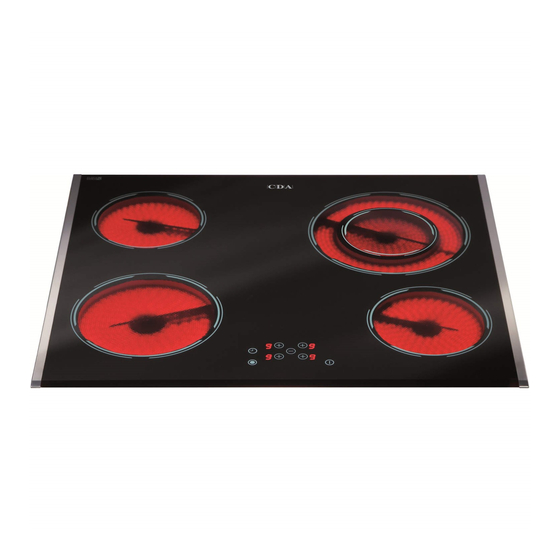
FEATURES 60 cm models Fig. 1.1 Electrical insulation Class I DISPLAY DESCRIPTION COOKING POINTS 13. Cooking zone indicator 1. Hi-light cooking zone Ø 180 mm - 1800 W (near every zone key): 2. Hi-light cooking zone Ø 140 mm - 1200 W 3. - Page 5 60 cm models Fig. 1.2 Electrical insulation Class I DISPLAY DESCRIPTION COOKING POINTS 13. Cooking zone indicator 1. Hi-light cooking zone Ø 180 mm - 1800 W (near every zone key): 2. Hi-light cooking zone Ø 140 mm - 1200 W 3.
- Page 6 60 cm models Fig. 1.3 Electrical insulation Class I DISPLAY DESCRIPTION COOKING POINTS 13. Cooking zone indicator 1. Double hi-light cooking zone (near every zone key): Ø 180/120 mm - 1700/700 W 2. Hi-light cooking zone Ø 180 mm - 1800 W = Line 3.
- Page 7 80 cm models Fig. 1.4 Electrical insulation Class I COOKING POINTS DISPLAY DESCRIPTION 1. Double hi-light cooking zone 13. Cooking zone indicator Ø 210/120 mm - 2200/750 W (near every zone key): 2. Hi-light cooking zone Ø 140 mm - 1200 W = Line 3.
-
Page 8: Important Note
COOKING ZONES FEATURES The ceramic surface of the hob allows a fast transmission of heat in the vertical direc- tion, from the heating elements underneath the ceramic glass to the pans set on it. The heat does not spread in a horizontal direction, so that the glass stays “cool” at only a few centimeters from the cooking plate. - Page 9 CO0KING HINTS Cooking zone power Power TYPE OF COOKING level level Switched OFF For melting operations (butter, chocolate). To maintain food hot and to heat small quantities of liquid (sauces, eggs). To heat bigger quantities; to whip creams and sauces. (vegetables, fruits, soups).
-
Page 10: Residual Heat Indicator
RESIDUAL HEAT INDICATOR When the temperature of a cooking plate is over 60°C, the relevant in the touch con- trol display is also lit-up to warn of heat on the surface of the hob. This symbol also stay on after the cooking plate has been switched off to shown that the hob surface is still hot. -
Page 11: Safety Hints
SAFETY HINTS DISTORTED • Before you switch the hob on, make PANBASE sure you know which touch controls the WRONG required cooking zone. We advise you to set the pan over the cooking zone before switching it on. • Do not use pots and pans with rough DISTORTED bases (pay attention to cookware made PANBASE... - Page 12 HOW TO USE THE TOUCH CONTROL NOT AVAILABLE IN THE MODEL IN FIG. 1.1 • Minute minder key. • Dial clock display. • Program key for automatic • Display automatic turn-off of the cooking zone turning off the cooking zone. with luminous points showing the involved zone.
- Page 13 HOW TO TURN THE TOUCH CONTROL ON AND OFF When first switching ON or after power failure, all displays and luminous point will be blinking for 1 second and will then go out while the touch control will be put in stand-by. STARTING •...
- Page 14 POWER IGNITION AND ADJUSTMENT OF A COOKING ZONE To turn ON a cooking zone its touch control must be switched ON (cf. section “HOW TO TURN THE TOUCH CONTROL ON AND OFF”). Press the key to activate the cooking zone to be lighted; then release the key. The point of the selected zone on the bot- tom right side of the display remains lighted Luminous...
- Page 15 FUNCTIONING OF THE DOUBLE AND OVAL COOKING ZONES The double and oval cooking hobs are OVAL ZONE DOUBLE ZONE consisting of two circuits, which may be used in the following modes: • Extended cooking zone: the first and second heating circuit are both switched •...
- Page 16 FAST AUTOMATIC HEATING OF THE COOKING ZONES This function permits fast heating up at the maximum power level, followed by heating at the preset power level. The duration of the automatic fast heating up period is preset and depends on the selected power level (cf. schedule) The touch control shall be switched ON (cf.
- Page 17 After a few seconds, the display reads (auto- matic) alternatively with the preset power level. The cooking zone will operate at its maximum power for the time indicated in the schedule. Upon its expiry, on the display will be switched off and the cooking zone will continue to function at the preset power level.
- Page 18 TURNING OFF THE COOKING ZONE Press the key to activate the cooking zone to be switched off; then release the key. The point at the bottom right side of the dis- This point play will light up to indicate activation will light up Method A...
- Page 19 PROTECTION AGAINST UNWANTED TURN-ON If the touch control finds that a key remains activated for more than 10 seconds, it will lock down and sends an audio warning signal to indicate the presence of an object on the keys. The displays read out the error code and a 10 sec.
- Page 20 SAFETY KEY-LOCK TO PROTECT CHILDREN This function locks the touch-control keys against unwanted activation. When set, this function remains permanent, even after the touch control is switched OFF and turned ON again and even after power failure or black-out. The safety lock can only be deactivated by a wilful operation. Before using the cooking zones, it is necessary temporarily to remove the safety locks which will be automatically reset after the touch-control is switched OFF.
- Page 21 TEMPORARILY UNLOCKING OF THE KEYS FOR COOKING PURPOSES After they have been switched ON, the touch control displays readout four indicating that the keys are locked. To temporarily unlock the keys, which remains active until the touch control is switched OFF: •...
- Page 22 PROGRAM FOR AUTOMATIC SWITCHING OFF THE COOKING ZONES (NOT AVAILABLE FOR MODEL IN FIG. 1.1) - This function permits to set a timer from 1 to 99 minutes for automatic turning OFF the cooking zones. - As many luminous points as there are cooking zones are located around the timer dis- play to indicate the zone on which the timer is activated.
- Page 23 Method B Fast adjustment at minutes. Press the key ; then release this key. The display will readout It will be possible to increase this time up minutes by pressing the timer key within 10 seconds. The time may be decreased by pressing the key The count down starts immediately after the setting has been completed and the luminous...
- Page 24 CONTROL AND/OR MODIFICATION OF THE TIME STATE OF THE PROGRAMMED ZONES (NOT AVAILABLE FOR MODEL IN FIG. 1.1) The time state of each cooking zone and its preset automatic turning off may be visualized Latest selected at any moment. zone The display will visualize the time of the latest selected zone.
-
Page 25: Minute Minder
MINUTE MINDER (NOT AVAILABLE FOR MODEL IN FIG. 1.1) This function permits to set an audio signal that is activated upon expiry of the count- down time, to be programmed in the 1 – 99 range. This function has no influence on the operation of the cooking hobs. The touch control shall be switched ON (cf. -
Page 26: Cleaning The Ceramic Hob
CLEANING AND MAINTENANCE CLEANING THE CERAMIC HOB Before you begin cleaning make sure that the hob is switched off. • Remove spillages and other types of incrustations. • Dust or food particles can be removed with a damp cloth. • If you use a detergent, please make sure that it is not abrasive or scouring. Abrasive or scouring powders can damage the glass surface of the hob. - Page 27 ADVICE FOR THE INSTALLER...
- Page 28 INSTALLATION CAUTION: This appliance shall only be serviced by authorized personnel. • This appliance is to be installed only by an authorised person according to the cur- rent local regulations and in observation of the manufacturer’s instructions. • Incorrect installation, for which the manufacturer accepts no responsibility, may cause personal injury of damage.
- Page 29 This cooktop can be built into a working surface 30 to 40 mm thick and 600 mm deep. In order to install the ceramic hob into the kitchen fixture, a hole with the dimensions shown in figures 5.1a-5.1b has to be made, keeping in consideration the following: •...
-
Page 30: Fastening The Cooktop
FASTENING THE COOKTOP Each cooktop is supplied with a set of tabs and screws to fasten it on units with a work- ing surface from 3 to 4 cm deep. The kit includes 4 tabs A and 4 self-threading screws B (fig. 5.4). •... -
Page 31: Electrical Connection
ELECTRICAL CONNECTION for the UNITED KINGDOM only IMPORTANT: Installation must be carried out according to the manufacturer's instructions. Incorrect installation may cause harm and damage to people, ani- mals or property, for which the manufacturer accepts no responsibility. Before carrying out any work on the electrical section of the appliance, it must be disconnected from the mains. - Page 32 • The wires in the mains lead are coloured in accordance with the following code: Green & Yellow = Earth Blue = Neutral Brown = Live. As the colours of the wires in the mains lead for the appliance, may not correspond with the coloured markings identifying the terminals in your spur box, proceed as fol- lows: 1) The wire which is coloured green and yellow must be connected to the terminal...
- Page 33 CONNECTING THE FEEDER CABLE To connect the feeder cable to the hob it is necessary to carry out the following opera- tions: • Unscrew the screw A of the terminal board at the bottom of the hob (fig. 6.1). • Unlock the 2 clips B and open the cover C. •...
-
Page 34: Electrical Requirements
for the other countries IMPORTANT: Installation must be carried out according to the manufacturer's instructions. Incorrect installation may cause harm and damage to people, ani- mals or property, for which the manufacturer accepts no responsibility. Before carrying out any work on the electrical section of the appliance, it must be disconnected from the mains. - Page 35 CONNECTING THE FEEDER CABLE To connect the feeder cable to the hob it is necessary to carry out the following opera- tions: • Unscrew the screw A of the terminal board at the bottom of the hob (fig. 6.4). • Unlock the 2 clips B and open the cover C. •...
- Page 36 N L2 220-240 V Fig. 6.6 380-415 V 2N Fig. 6.7...
- Page 40 Descriptions and illustrations in this booklet are given as simply indicative. The manufacturer reserves the right, considering the characteristics of the models described here, at any time and without notice, to make eventual necessary modifications for their construction or for commercial needs. Cod.