Advertisement
Safe Operation Practices • Set-Up • Operation • Maintenance • Service • Troubleshooting • Warranty
O
'
M
peratOr
s
anual
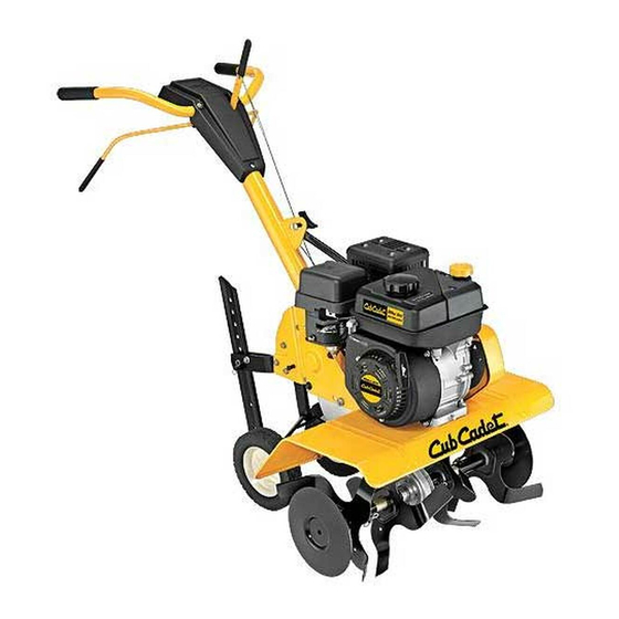
Front Tine Tiller — Model FT24 R
WARNING
READ AND FOLLOW ALL SAFETY RULES AND INSTRUCTIONS IN THIS MANUAL
BEFORE ATTEMPTING TO OPERATE THIS MACHINE.
FAILURE TO COMPLY WITH THESE INSTRUCTIONS MAY RESULT IN PERSONAL INJURY.
CUB CADET LLC, P.O. BOX 361131 CLEVELAND, OHIO 44136-0019
Printed In USA
Form No. 769-09696
(February 24, 2014)
Advertisement
Table of Contents

Related Manuals for Cub Cadet FT24 R


Summary of Contents for Cub Cadet FT24 R
- Page 1 READ AND FOLLOW ALL SAFETY RULES AND INSTRUCTIONS IN THIS MANUAL BEFORE ATTEMPTING TO OPERATE THIS MACHINE. FAILURE TO COMPLY WITH THESE INSTRUCTIONS MAY RESULT IN PERSONAL INJURY. CUB CADET LLC, P.O. BOX 361131 CLEVELAND, OHIO 44136-0019 Printed In USA Form No. 769-09696...
-
Page 2: Table Of Contents
See How-to Maintenance and Parts Installation Videos at www.cubcadet.com/tutorials ◊ Call a Customer Support Representative at (800) 965-4CUB ◊ Locate your nearest Cub Cadet Dealer at (877) 282-8684 ◊ Write to Cub Cadet LLC • P.O. Box 361131 • Cleveland, OH • 44136-0019... -
Page 3: Safe Operation Practices
Important Safe Operation Practices WARNING! This symbol points out important safety instructions which, if not followed, could endanger the personal safety and/or property of yourself and others. Read and follow all instructions in this manual before attempting to operate this machine. Failure to comply with these instructions may result in personal injury. - Page 4 When practical, remove gas-powered equipment After striking a foreign object, stop the engine, disconnect from the truck or trailer and refuel it on the ground. the spark plug wire and ground against the engine. If this is not possible, then refuel such equipment on Thoroughly inspect the machine for any damage.
- Page 5 Spark Arrestor If the fuel tank has to be drained, do this outdoors. Observe proper disposal laws and regulations for gas, oil, WARNING! This machine is equipped with an etc. to protect the environment. internal combustion engine and should not be used According to the Consumer Products Safety Commission on or near any unimproved forest-covered, (CPSC) and the U.S.
- Page 6 Safety Symbols This page depicts and describes safety symbols that may appear on this product. Read, understand, and follow all instructions on the machine before attempting to assemble and operate. Symbol Description READ THE OPERATOR’S MANUAL(S) Read, understand, and follow all instructions in the manual(s) before attempting to assemble and operate WARNING—...
-
Page 7: Assembly & Set-Up
Assembly & Set-Up Contents of Carton • One Tiller • One Handlebar Assembly • One Depth Gage Assembly • One Operator’s Manual • One Engine Operator’s Manual Assembly Hook the “Z” end of the forward clutch cable (A) into the forward tine engagement lever Figure 3-2. - Page 8 Remove the hex bolt and cupped washer from the right Insert the carriage bolt through the welded bracket on the side of the frame. Hold the cable guide bracket on the left handle, bell washer, handle brace and into the hand knob. side of frame as it will fall when the bolt is removed.
- Page 9 Adjustments Turn the cable collar section one or two turns to increase or decrease tension on the cable. See Figure 3-8. Wheels Retighten the lock nut against the cable collar. See Figure 3-8. The tiller is shipped with the wheels adjusted so that the With the forward and reverse tine engagement handles in machine sits level.
-
Page 10: Controls & Features
Controls & Features Reverse Tine Engagement Lever Handle Forward Tine Engagement Lever Handle Knob Depth Stake End Cap Tiller Tines Depth Stake Engine Controls The depth stake controls the tilling depth. See the separate Engine Operator’s Manual for information and Tines &... -
Page 11: Operation
Operation Starting & Stopping the Engine Yoke to Back Place the wheel yoke so that wheels are toward the rear — WARNING! Read, understand, and follow all the closest to depth stake — for deep tilling and cultivating. See instructions and warnings posted on the machine Figure 5-2. -
Page 12: Tilling Procedure
Handle Pressure Cultivating Procedures Further control of the tilling depth and travel speed can be For cultivating, a two to three inch depth is desirable. The tine obtained by variation of pressure on the handles. width can be reduced to 13 inches by removing the outer tines completely from the tiller. -
Page 13: Maintenance & Adjustment
Maintenance & Adjustments End Caps WARNING! Disconnect the spark plug wire and ground it against the engine before performing any The end cap, which is used to prevent tilled soil from overflowing repairs. onto unwanted areas, are removable from the axle. Remove the hairpin clip and clevis pin that secure each end cap and slide the Maintenance end caps off the axle. - Page 14 Off-Season Storage If the tiller will not be used for a period longer than 30 days, the following steps should be taken to prepare the tiller for storage. Clean the exterior of the engine and the entire tiller thoroughly. Lubricate the tiller as described in the lubrication instructions.
-
Page 15: Service
Service Belt Replacement Remove belt from transmission pulley and then from around the reverse idler pulley. See Figure 7-2. Reverse Drive Belt Your tiller has been engineered with a belt made of special material (Kevlar Tensile) for longer life and better performance. It should not be replaced with an off-the-shelf belt. - Page 16 Forward Drive Belt The forward idler belt will not clear the belt keepers near the engine pulley. You must remove the reverse idler Remove the reverse drive belt as instructed in the previous bracket to allow the belt to move off of the engine pulley. section.
-
Page 17: Troubleshooting
Troubleshooting Problem Cause Remedy Tines do not engage 1. Foreign object lodged in tines 1. Dislodge foreign object 2. Tine clevis pin(s) missing 2. Replace tine clevis pin(s) 3. Pulley and idler not in correct adjustment 3. Take tiller to authorized service dealer 4. -
Page 18: Replacement Parts
Replacement Parts Component Part Number and Description 642-0002 Inner Right Hand Tine 642-0003 Inner Left Hand Tine 642-0023 Outer Left Hand Tine 642-0024 Outer Right Hand Tine 714-04043 Cotter Pin 911-0415 Clevis Pin 754-0428 Forward V-Belt, 754-0429 Reverse V-Belt 946-0918 Forward Cable 746-0953 Reverse Cable... - Page 19 Notes...
-
Page 20: Warranty
MANUFACTURER’S LIMITED WARRANTY FOR EDGERS, STRING TRIMMERS & TILLERS The limited warranty set forth below is given by Cub Cadet LLC Cub Cadet does not extend any warranty for products sold with respect to new merchandise purchased and used in the United...