Cub Cadet FT24 Operator's Manual
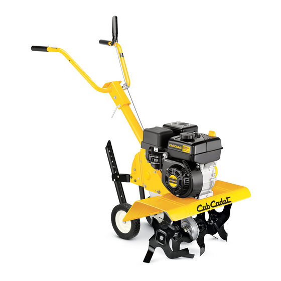
Front tine tiller
Hide thumbs
Also See for FT24:
- Parts manual (93 pages) ,
- Operation manual (48 pages) ,
- Operator's manual (36 pages)
Advertisement
Table of Contents
Safe Operation Practices • Set-Up • Operation • Maintenance • Service • Troubleshooting • Warranty
O
'
M
peratOr
s
anual
Front Tine Tiller — Model FT24
WARNING
READ AND FOLLOW ALL SAFETY RULES AND INSTRUCTIONS IN THIS MANUAL
BEFORE ATTEMPTING TO OPERATE THIS MACHINE.
FAILURE TO COMPLY WITH THESE INSTRUCTIONS MAY RESULT IN PERSONAL INJURY.
CUB CADET LLC, P.O. BOX 361131 CLEVELAND, OHIO 44136-0019
Printed In USA
Form No. 769-05497
(October 27, 2009)
Advertisement
Table of Contents

Related Manuals for Cub Cadet FT24


Summary of Contents for Cub Cadet FT24
- Page 1 READ AND FOLLOW ALL SAFETY RULES AND INSTRUCTIONS IN THIS MANUAL BEFORE ATTEMPTING TO OPERATE THIS MACHINE. FAILURE TO COMPLY WITH THESE INSTRUCTIONS MAY RESULT IN PERSONAL INJURY. CUB CADET LLC, P.O. BOX 361131 CLEVELAND, OHIO 44136-0019 Printed In USA Form No. 769-05497...
-
Page 2: Table Of Contents
Choose from the options below: ◊ Visit us on the web at www.cubcadet.com ◊ Locate your nearest Cub Cadet Dealer at (877) 282-8684 ◊ Write to Cub Cadet LLC • P.O. Box 361131 • Cleveland, OH • 44136-0019... -
Page 3: Safe Operation Practices
Important Safe Operation Practices WARNING! This symbol points out important safety instructions which, if not followed, could endanger the personal safety and/or property of yourself and others. Read and follow all instructions in this manual before attempting to operate this machine. Failure to comply with these instructions may result in personal injury. - Page 4 When practical, remove gas-powered equipment After striking a foreign object, stop the engine, disconnect from the truck or trailer and refuel it on the ground. the spark plug wire and ground against the engine. If this is not possible, then refuel such equipment on Thoroughly inspect the machine for any damage.
-
Page 5: Spark Arrester
Spark Arrester If the fuel tank has to be drained, do this outdoors. Observe proper disposal laws and regulations for gas, oil, WARNING! This machine is equipped with an etc. to protect the environment. internal combustion engine and should not be used According to the Consumer Products Safety Commission on or near any unimproved forest-covered, (CPSC) and the U.S. - Page 6 Safety Symbols This page depicts and describes safety symbols that may appear on this product. Read, understand, and follow all instructions on the machine before attempting to assemble and operate. Symbol Description READ THE OPERATOR’S MANUAL(S) Read, understand, and follow all instructions in the manual(s) before attempting to assemble and operate WARNING—...
-
Page 7: Assembly & Set-Up
Assembly & Set-Up Contents of Carton • One Tiller • One Handlebar Assembly • One Depth Gage Assembly • One Operator’s Manual • One Engine Operator’s Manual Assembly Hook the “Z” end of the forward clutch cable (A) into the forward tine engagement lever Fig. - Page 8 Remove the hex bolt and cupped washer from the right Insert the carriage bolt through the welded bracket on the side of the frame. Hold the cable guide bracket on the left handle, bell washer, handle brace and into the hand knob. side of frame as it will fall when the bolt is removed.
- Page 9 Set-Up Insert the depth stake into the depth gage bracket assembly as seen in Fig. 3–7. Gas & Oil Fill-Up Service the Engine with gasoline and oil as instructed in the separate Engine Operator’s Manual packed with your tiller. Read the instructions carefully.
-
Page 10: Controls
Controls and Features Reverse Tine Engagement Lever Handle Forward Tine Engagement Lever Handle Knob Depth Stake End Cap Tiller Tines Figure 4-1 Engine Controls Tines and End Caps See the separate Engine Operator’s Manual for additional Tilling tines and end caps are used to cultivate, furrow and information and functions of the engine controls. -
Page 11: Operation
Operation Starting the Engine Setting the Depth Yoke Forward WARNING! Read, understand, and follow all the instructions and warnings posted on the machine Place the wheel yoke so that wheels are forward (nearest to tines) and in this manual before operating. for shallow tilling, cultivating and transport. -
Page 12: Tilling Procedure
Tilling Procedure Depth Stake The depth stake acts as a brake for the tiller and controls the When tilling, leave approximately eight inches of untilled soil depth and speed at which the machine will operate. Remove the between the first and second tilling paths, then make the third clevis pin and hairpin clip to raise or lower depth stake. - Page 13 Cultivating Procedures For cultivating, a two to three inch depth is desirable. The tine width can be reduced to 13 inches by removing the outer tines completely from the tiller. See the Maintenance & Adjustments Section for instructions on removing the tines. When laying out plant rows, be sure to allow enough width to permit cultivation between the rows.
-
Page 14: Maintenance & Adjustment
Maintenance & Adjustments Adjustments WARNING! Disconnect the spark plug wire and ground it against the engine before performing any Cable Adjustment repairs. From time to time you may need to adjust the tension on the Maintenance forward and reverse tine engagement cables. See Fig. 6-1. Engine Refer to the separate Engine Operator’s Manual for engine maintenance instructions. - Page 15 End Caps Turn the cable collar section one or two turns to increase or decrease tension on the cable. See Fig. 6-3. The end cap, which is used to prevent tilled soil from overflowing onto unwanted areas, are removable from the axle. Remove the hairpin clip and clevis pin that secure each end cap and slide the end caps off the axle.
- Page 16 Off-Season Storage If the tiller will not be used for a period longer than 30 days, the following steps should be taken to prepare the tiller for storage. Clean the exterior of the engine and the entire tiller thoroughly. Lubricate the tiller as described in the lubrication instructions.
-
Page 17: Engine Maintenance
Engine Maintenance Maintenance Schedule Each Use or Every Season Every Season Every Season Service First 5 Hours Every 5 Hrs. or 25 Hours or 50 Hours or 100 Hours Dates Check Engine Oil Level Change Engine Oil Check Air Cleaner Service Air Cleaner Check Spark Plug Replace Spark Plug... -
Page 18: Air Filter
20w40, 20w50 15w40, 15w50 10w40 10w30 (ºC) -30º -20º -10º 0º 10º 20º 30º 40º (ºF) -20º 0º 20º 40º 60º 80º 100º Drain Ambient Temperature Figure 6-1 Reinstall the drain plug and tighten it securely. Single Viscosity Refill with the recommended oil and check the oil level. Multi Viscosity Refer to the Assembly &... - Page 19 To clean foam element, separate it from the paper element Check that the spark plug washer is in good condition and wash in liquid detergent and water. Allow to dry and thread the spark plug in by hand to prevent cross- thoroughly before using.
- Page 20 Off-Season Storage Engines stored between 30 and 90 days need to be treated with a gasoline stabilizer and engines stored over 90 days need to be drained of fuel to prevent deterioration and gum from forming in fuel system or on essential carburetor parts. If the gasoline in your engine deteriorates during storage, you may need to have the carburetor, and other fuel system components, serviced or replaced.
-
Page 21: Service
Service Belt Replacement Remove belt from transmission pulley and then from around the reverse idler pulley. See Fig. 7–2. Reverse Drive Belt Your tiller has been engineered with a belt made of special material (Kevlar Tensile) for longer life and better performance. It should not be replaced with an off-the-shelf belt. - Page 22 Forward Drive Belt The forward idler belt will not clear the belt keepers near the engine pulley. You must remove the reverse idler Remove the reverse drive belt as instructed in the previous bracket to allow the belt to move off of the engine pulley. section.
-
Page 23: Troubleshooting
Troubleshooting Problem Cause Remedy Engine fails to start Fuel tank empty or stale fuel Fill tank with clean, fresh gasoline Throttle control lever not in correct starting Move throttle lever to start position position (if equipped) Blocked fuel line Clean fuel line Dirty air cleaner Refer to the Engine Operator’s Manual Choke not in ON position... -
Page 24: Replacement Parts
Replacement Parts Component Part Number and Description 642-0002 Inner Right Hand Tine 642-0003 Inner Left Hand Tine 642-0023 Outer Left Hand Tine 642-0024 Outer Right Hand Tine 714-04043 Cotter Pin 911-0415 Clevis Pin 754-0428 Forward V-Belt, 754-0429 Reverse V-Belt 946-0918 Forward Cable 746-0953 Reverse Cable... - Page 25 Notes...
- Page 26 11— n ectiOn Otes...
- Page 27 11 — n ectiOn Otes...
- Page 28 MANUFACTURER’S LIMITED WARRANTY FOR EDGERS, STRING TRIMMERS & TILLERS The limited warranty set forth below is given by Cub Cadet LLC with c. Cub Cadet does not extend any warranty for products sold or respect to new merchandise purchased and used in the United States,...