Table of Contents
Advertisement
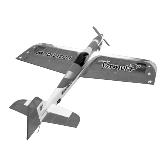
Model Tech makes 3D more fun with more performance. The no-compromise Magic Formula 3D ARF is a true aerobatic machine.
Two years and thousands of R&D hours went into the making of this unique and beautiful flying machine.
The Magic Formula 3D ARF is drawn in 3D-CAD, then each kit is cut on the latest large-footprint laser cutters and assembled by
master craftsmen in precision-made jigs. Finally, after sanding, test-fitting and checking alignment, each airplane is hand-covered
using real iron-on covering.
In the air, you'll find the Magic Formula 3D ARF to have the performance envelope you're looking for in a larger 3D-style aircraft.
Slow speed is amazing, transition to hover is easy and high alpha maneuvers are stable, and with the right powerplant, you'll be
amazed at the vertical performance. Rolling Harriers, hovering, flat spins, Blenders and torque rolls...you'll look like a world-class
pro flying your own Magic Formula 3D ARF.
INSTRUCTIONS FOR FINAL ASSEMBLY
The Model Tech Magic Formula 3D ARF is distributed
exclusively in the USA by Global Hobby Distributors
and in the U.K. by YT International
All contents copyright © 2004, Global Hobby
Distributors Version V1.0 December 2004
IMPORTANT
The Model Tech Magic Formula 3D ARF is not intended for inexperienced pilots. It is not a trainer. If you are
not comfortable flying high-performance aerobatic aircraft, we strongly suggest returning the airplane (brand new, in the box with
all original packaging and your dated sales receipt) to the place of purchase.
Magic Formula 3D ARF Specifications:
Wing Span: 60 Inches (1524mm)
Wing Area: 1027 Square Inches (66.3dm
Length: 64 Inches (1630mm)
Weight RTF: 6.1 - 7.7 Pounds (2.75-3.5kg)
Wing Loading: 13.6-17.25 oz/sq in (41-52 g/sqdm)
Functions: Ailerons, Elevator, Rudder and Throttle
Engine Required: .46 - .61 Two-Stroke or .61-.70 Four-Stroke
Radio Required: 4 Channel or More w/6 Standard BB Servos
1
2
)
Kit Product Number 123771
Advertisement
Table of Contents

Related Manuals for Model Tech Magic Formula 3D ARF


Summary of Contents for Model Tech Magic Formula 3D ARF
- Page 1 Two years and thousands of R&D hours went into the making of this unique and beautiful flying machine. The Magic Formula 3D ARF is drawn in 3D-CAD, then each kit is cut on the latest large-footprint laser cutters and assembled by master craftsmen in precision-made jigs.
-
Page 2: Table Of Contents
OUR GUARANTEE Model Tech guarantees this kit to be free from defects in both material and workmanship at the date of purchase. This does not cover any component parts damaged by use, misuse or modification. In no case shall Model Tech's liability exceed the original cost of the purchased kit. -
Page 3: Introduction
We urge you to come check out our website at http://globalservices.globalhobby.com. There you will find public message boards frequented by other Model Tech product owners and the Model Tech support staff. This is a great place to learn about new products, get help and suggestions for your current Model Tech products or just simply hang out and chat with people that share your same interests. -
Page 4: Section 1: Our Recommendations
This section describes our recommendations to help you in deciding which types of accessories to purchase for your new Model Tech Magic Formula 3D ARF. Please read through this entire section very carefully. We have provided you with tips and recommendations that, if followed, will result in a great flying airplane. Failure to follow our recommendations may result in a poor flying airplane. -
Page 5: Section 2: Tools And Supplies Required
SECTION 2: TOOLS AND SUPPLIES REQUIRED The tools and supplies listed below will be necessary to finish the assembly of your new Model Tech Magic Formula 3D ARF. We suggest having these items on hand before beginning assembly. Kwik Bond Thin C/A # 887500... -
Page 6: Section 4: Kit Contents
SECTION 4: KIT CONTENTS We have organized the parts as they come out of the box for easier identification during assembly. Before you begin assembly, group the parts as we list them below. This will ensure that you have all of the parts before you begin assembly and it will also help you become familiar with each part. -
Page 7: Section 5: Wing Assembly
MISCELLANEOUS WING PARTS To convert inches into millimeters: (1) Plywood Wing Joiner (W34) Inches x 25.4 = mm (1) Plywood Wing-Screw Doubler (W35) To convert millimeters into inches: (2) M4 x 40mm Machine Screws Millimeters / 25.4 = in (2) M4 Flat Washers A complete replacement parts list, along with part numbers for ordering convenience, can be found on page # 44. - Page 8 Using a modeling knife, cut away and remove the covering material from over the aileron servo mounting hole in the bottom of the wing panel. The hole is located 13-1/2" out from the root rib and 3-1/4" in front of the trailing edge. Tie the end of the length of preinstalled string in the servo mounting hole to the servo extension plug and use it to pull the servo extension lead through the wing panel.
- Page 9 Use a ruler and a pencil to locate and draw a vertical centerline on one side of the plywood wing joiner. IMPORTANT The plywood wing joiner is straight. There is no top or bottom. Test-fit the wing joiner into each wing panel. It should slide easily into each wing panel up to the centerline you drew.
-
Page 10: Section 6: Wing Mounting
Mix a generous amount of 30 minute epoxy. Working with only one wing panel for now, apply a thin layer of epoxy inside the wing joiner box and to only half of the wing joiner. Make sure to cover the top and bottom, as well as the sides, and use enough epoxy to fill any gaps. - Page 11 Place the wing-screw doubler onto the bottom of the wing and align the predrilled holes in the wing-screw doubler with the predrilled holes in the wing. While holding the wing-screw doubler in place, trace an outline around it, using a pencil. The back edge of the wing-screw doubler should be about 1/16"-3/32"...
-
Page 12: Section 7: Belly Pan Installation
SECTION 7: BELLY PAN INSTALLATION YOU'LL NEED THE FOLLOWING PARTS FROM THE KIT: (1) Belly Pan YOU'LL NEED THE FOLLOWING TOOLS AND SUPPLIES: Wilhold Silicon Sealant 220 Grit Sandpaper w/Sanding Block Excel Modeling Knife Masking Tape Ernst Airplane Stand Paper Towels Pencil Waxed Paper STEP 1: ALIGNING THE BELLY PAN... -
Page 13: Section 8: Stabilizer Installation
STEP 2: INSTALLING THE BELLY PAN Remove the wing, lay a long piece of waxed paper over the wing saddle, then reinstall the wing, making sure that the ends of the waxed paper are covering the joints between the fuselage and the leading and trailing edges of the wing. - Page 14 Using a modeling knife, cut away and remove the covering material from over the horizontal stabilizer mounting slot in each side of the fuselage. The slot is located 7" in front of the back edge of the fuselage and is 4" long and 5/16" wide. Slide the horizontal stabilizer into the mounting slot and center it by carefully measuring out from each side of the fuselage to each end of the stabilizer (at the trailing edge only for now).
- Page 15 When you're satisfied that the stabilizer is square to the wing, use a pencil to draw a couple of marks on each side of the front of the stabilizer where it and the fuselage sides meet, then use a couple of T-Pins to hold the stabilizer firmly in place and aligned. With the stabilizer held firmly in place, look from the front of the airplane at both the wing and the stabilizer.
- Page 16 Mix and apply a generous amount of 30 minute epoxy to ONLY the top and bottom gluing surfaces of the stabilizer. Push the stabilizer into place and realign it, double-checking all of your measurements once more before the epoxy sets up. Quickly remove any excess epoxy and use T-Pins to hold the stabilizer in place and aligned until the epoxy has fully cured.
-
Page 17: Section 9: Control Surface Hinging
The Magic Formula 3D ARF uses C/A-style hinges to hinge the control surfaces. These hinges are designed to be glued into place using thin C/A. Do not glue these hinges into place using any other type of glue, such as thick C/A or epoxy. Use of any adhesive other than thin C/A could result in failure of the hinges during flight. - Page 18 Slide one hinge into each hinge slot in one aileron, making sure that you push each hinge in up to the T-Pins. Don't glue the hinges into the aileron yet, though. IMPORTANT Notice that the ailerons are hinged along the top. This is normal and by design. Push the aileron and its hinges into the hinge slots in the trailing edge of the corresponding side of the wing.
-
Page 19: Section 10: Tail Skid Installation
STEP 3: HINGING THE RUDDER Hinge the rudder, using the same techniques that you used to hinge the ailerons and the elevator halves. The rudder is hinged using three hinges. When hinging the rudder, there should be a 1/16" wide gap between the end of the stabilizer and the rudder counterbalance. -
Page 20: Section 11: Landing Gear Installation
Remove the nylon mounting straps and drill four 1/16" diameter pilot holes into the fuselage at the marks you drew. Install the two nylon mounting straps, using four M2 x 10mm wood screws, to secure the tail skid into place. SECTION 11: LANDING GEAR INSTALLATION YOU'LL NEED THE FOLLOWING PARTS FROM THE KIT: (4) M4 Lock Nuts... - Page 21 STEP 2: INSTALLING THE WHEELS AND WHEEL PANTS Using a modeling knife, carefully cut away the material from over the wheel opening in one wheel pant. Use 220 grit sandpaper to sand the edges of the wheel pant opening smooth. Drill a 5/32"...
- Page 22 Slide one M4 flat washer up against the hex nut, then slide the wheel and threaded axle assembly into the slot in the wheel pant, making sure that the flat washer is on the inside of the wheel pant . Slide the end of the threaded axle through the predrilled hole in the main gear bracket.
-
Page 23: Section 12: Engine Installation
SECTION 12: ENGINE INSTALLATION YOU'LL NEED THE FOLLOWING PARTS FROM THE KIT: (2) Engine Mounting Beams (4) M4 Lock Nuts (4) M4 x 20mm Socket-Cap Screws (12) M4 Flat Washers (1) Spinner Assembly w/Backplate & Screws (4) M4 x 25mm Socket-Cap Screws YOU'LL NEED THE FOLLOWING TOOLS AND SUPPLIES: 3/32"... -
Page 24: Section 13: Throttle Control System Installation
With the fuselage upside down, set the engine onto the engine mounting beams. Using a ruler, measure the distance from the firewall to the back of the spinner backplate. Adjust the depth of the engine so that the measurement is 4-1/2". Using a pencil, carefully mark the locations of the engine mounting holes onto the engine mounting beams. - Page 25 Install the throttle servo into the forward hole in the plywood servo tray, making sure to drill 1/16" diameter pilot holes for the mounting screws. IMPORTANT The servo output shaft should be toward the front of the fuselage, as shown. STEP 2: INSTALLING THE THROTTLE PUSHROD WIRE IMPORTANT Since we are using a four-stroke engine in our model, attaching the throttle pushrod wire to the engine's throttle...
- Page 26 Enlarge the hole in the servo arm that is 11/16" out from the center of the servo arm, using a 5/64" diameter drill bit. Install the adjustable pushrod connector into the enlarged hole in the servo arm. IMPORTANT When threading on the knurled nut, don't tighten the nut completely.
-
Page 27: Section 14: Fuel Tank Assembly And Installation
SECTION 14: FUEL TANK ASSEMBLY AND INSTALLATION YOU'LL NEED THE FOLLOWING PARTS FROM THE KIT: (1) 320cc Fuel Tank (1) Fuel Pick-Up "Clunk" (1) Large Diameter Metal Plate (1) M3 x 20mm Machine Screw (1) Small Diameter Metal Plate (1) Silicone Fuel Tubing (1) Neck-Reinforcement Ring (3) Aluminum Tubing (1) Rubber Stopper... - Page 28 STEP 2: INSTALLING THE STOPPER ASSEMBLY Push the metal neck-reinforcement ring over the neck of the molded fuel tank opening, then carefully push the stopper assembly into the molded hole in the front of the fuel tank and rotate the stopper assembly until the aluminum vent tube rests inside the bubble in the top of the fuel tank.
- Page 29 SECTION 15: ELEVATOR CONTROL SYSTEM INSTALLATION YOU'LL NEED THE FOLLOWING PARTS FROM THE KIT: (2) 6-3/8" Threaded Wires w/90º Bends (2) Nylon 90º Snap-Keepers (2) Nylon Control Horns w/Backplates (4) M2 x 12mm Machine Screws (2) Nylon Clevises YOU'LL NEED THE FOLLOWING TOOLS AND SUPPLIES: Kwik Bond Thin C/A 1/16"...
-
Page 30: Section 15: Elevator Control System Installation
STEP 2: INSTALLING THE CONTROL HORNS IMPORTANT Before installing the control horns and pushrod assemblies, please refer to section 23 on page # 41 about sealing the control surface hinge gaps. It is strongly recommended that you do this, and it's much easier to do it now than later. Position one nylon control horn onto one elevator half. - Page 31 Connect your radio system and plug the left-side elevator servo into the receiver. Center the servo by double-checking that the elevator trim lever on your transmitter is centered, then use a couple of pieces of masking tape, taped between the elevator half and the stabilizer, to hold the elevator half centered.
-
Page 32: Section 16: Rudder Control System Installation
SECTION 16: RUDDER CONTROL SYSTEM INSTALLATION YOU'LL NEED THE FOLLOWING PARTS FROM THE KIT: (4) M2 x 12mm Machine Screws (2) 38-1/2" Threaded Wires w/90º Bends (2) Nylon Control Horns (w/o Backplates) (4) M2 Flat Washers (2) Nylon Clevises (4) M2 Hex Nuts (2) Nylon 90º... - Page 33 Install the 90º bend in each 38-1/2" long pushrod wire into the holes that you enlarged, using the nylon snap keepers provided. When installing the snap keepers, make sure they "snap" firmly into place over the pushrod wires. The pushrod wires should be orientated on top of the servo arm, as shown.
-
Page 34: Section 17: Aileron Control System Installation
Use a piece of masking tape, taped between the rudder and the stabilizer, to hold the rudder centered. Thread two nylon clevises onto the pushrod wires and snap them into the outermost hole in the control horns. Hold the pushrod wires with a pair of pliers to prevent them from turning or twisting when installing the clevises. - Page 35 Install the 90º bend in one 3-1/8" long pushrod wire into the hole that you enlarged, using the nylon snap keeper provided. When installing the snap keeper, make sure it "snaps" firmly into place over the pushrod wire. The pushrod wire should be orientated on top of the servo arm, as shown.
-
Page 36: Section 18: Cowling Installation
If you will be flying your Magic Formula 3D ARF using a computer radio with mixing capabilities, you may want to plug each aileron servo lead into your receiver separately (into Ch. 1 and Ch. 6) to take advantage of your radio's mixing capabilities. - Page 37 WARNING To prevent dust and debris from entering your engine during the fitting and aligning of the cowling, we strongly suggest covering your engine's exhaust port, carburetor opening and needle valve inlet with small pieces of paper towel. Measure and mark the location on the cowling that you must cut out to clear your engine's cylinder head.
-
Page 38: Section 19: Canopy Installation
At this time you should mark and cut out the areas of the cowling necessary to give you access to your engine's high and low speed needle valves and choke lever (if featured). You should also install a fueling valve into a convenient location on the side of the cowling, so that you can fill the fuel tank. -
Page 39: Section 20: Final Assembly
Before gluing the canopy into place, clean the inside of it to remove any fingerprints, dust and small debris. When satisfied with the alignment, carefully glue the canopy into place, using a thin layer of Pacer Formula 560 Canopy Glue. Remove any excess glue before it dries, using a paper towel and water, and use pieces of masking tape to hold the canopy in place until the glue fully cures. -
Page 40: Section 21: Balancing The Magic Formula 3D Arf
C/G be located any farther back than 5-1/2" (140mm). IMPORTANT Balance the Magic Formula 3D ARF with the fuel tank empty and the airplane fully assembled. Install the wing onto the fuselage. Apply two short pieces of masking tape onto the top of the wing, 4-1/2" (114mm) back from the leading edge, measured at the fuselage sides. -
Page 41: Section 23: Aircraft Setup Information
SECTION 23: AIRCRAFT SETUP INFORMATION Before adjusting the control throws and flying your new Magic Formula 3D ARF, there are some points about the airplane's setup that you should be aware of. We strongly suggest following these suggestions to get the most enjoyment out of your airplane. -
Page 42: Section 24: Control Throws
SECTION 25: COMPUTER RADIO SETUP AND 3D CONTROL THROWS Although you don't have to use a computer radio to enjoy the flying qualities of the Magic Formula 3D ARF, if you're planning on doing extreme 3D aerobatics, it is recommended. Before making any adjustments, please read and understand your radio's setup manual. -
Page 43: Section 26: Preflight Check And Safety
FLAPERON AND SPOILERON MIXING: Plugging the servos separately into the receiver (one into channel 1 and one into channel 6) will allow the use of flaperons (both ailerons down at the same time) and spoilerons (both ailerons up at the same time). These functions can then be mixed with the elevator for extreme pitch changes (high-alpha) useful in extreme 3D aerobatic maneuvers. -
Page 44: Section 27: Magic Formula 3D Arf Flight-Trimming Chart
SECTION 27: MAGIC FORMULA 3D ARF FLIGHT-TRIMMING CHART After you have test-flown and done the initial trim changes to the airplane, use this trimming chart to begin trimming your airplane. Following and adhering to this chart will result in the ability to diagnose trim problems and correct those problems using the simple adjustments shown below. -
Page 45: Section 28: Replacement Parts
SECTION 28: REPLACEMENT PARTS We stock a complete line of replacement parts for your Model Tech Magic Formula 3D ARF. Listed below are the replacement parts that are available along with their respective part numbers for easy ordering convenience. We suggest ordering directly from your local dealer. -
Page 47: Product Evaluation Sheet
Please List any Other Modeling Interests or any Additional Information about This Product: ______________________ _____________________________________________________________________________________ _____________________________________________________________________________________ _____________________________________________________________________________________ _____________________________________________________________________________________ The Model Tech Magic Formula 3D ARF is distributed exclusively by Global Hobby Distributors 18480 Bandilier Circle, Fountain Valley, CA 92708 QC # All contents copyright © 2004, Global Hobby Distributors Version V1.0 December 2004... - Page 48 _____________________________ _____________________________ Post Office will not deliver _____________________________ without proper postage (Return Address Here) Global Hobby Distributors Attn: Global Services 18480 Bandilier Circle Fountain Valley CA 92728-8610 Fold along dotted line...